Power electronic handbook
Подождите немного. Документ загружается.

18 AC–AC Converters 499
Voltage
Inverting
Desired
output
Load
voltage
Load
voltage
InvertingRectifying Rectifying
Current
(a)
(b)
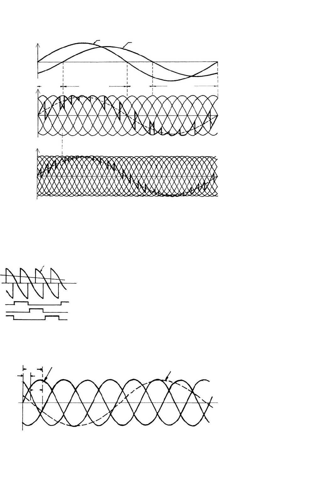
FIGURE 18.25 Cycloconverter load voltage waveforms with lagging power factor load: (a) six-pulse connection and (b) twelve-pulse connection.
TG pA
Modulating wave
ωt
e
a
e
b
e
c
e
r
TG pB
TG pC
FIGURE 18.26 Deriving firing signals for one converter group of a
three-pulse cycloconverter.
ABC
C
m
= E
m
sinω
l
te
r
= E
r
sinω
o
t
ω
l
t
φ
α
α
FIGURE 18.27 Derivation of the cosine modulating voltages.
output voltage waveforms which coincide with the positive
and negative current half cycles, respectively.
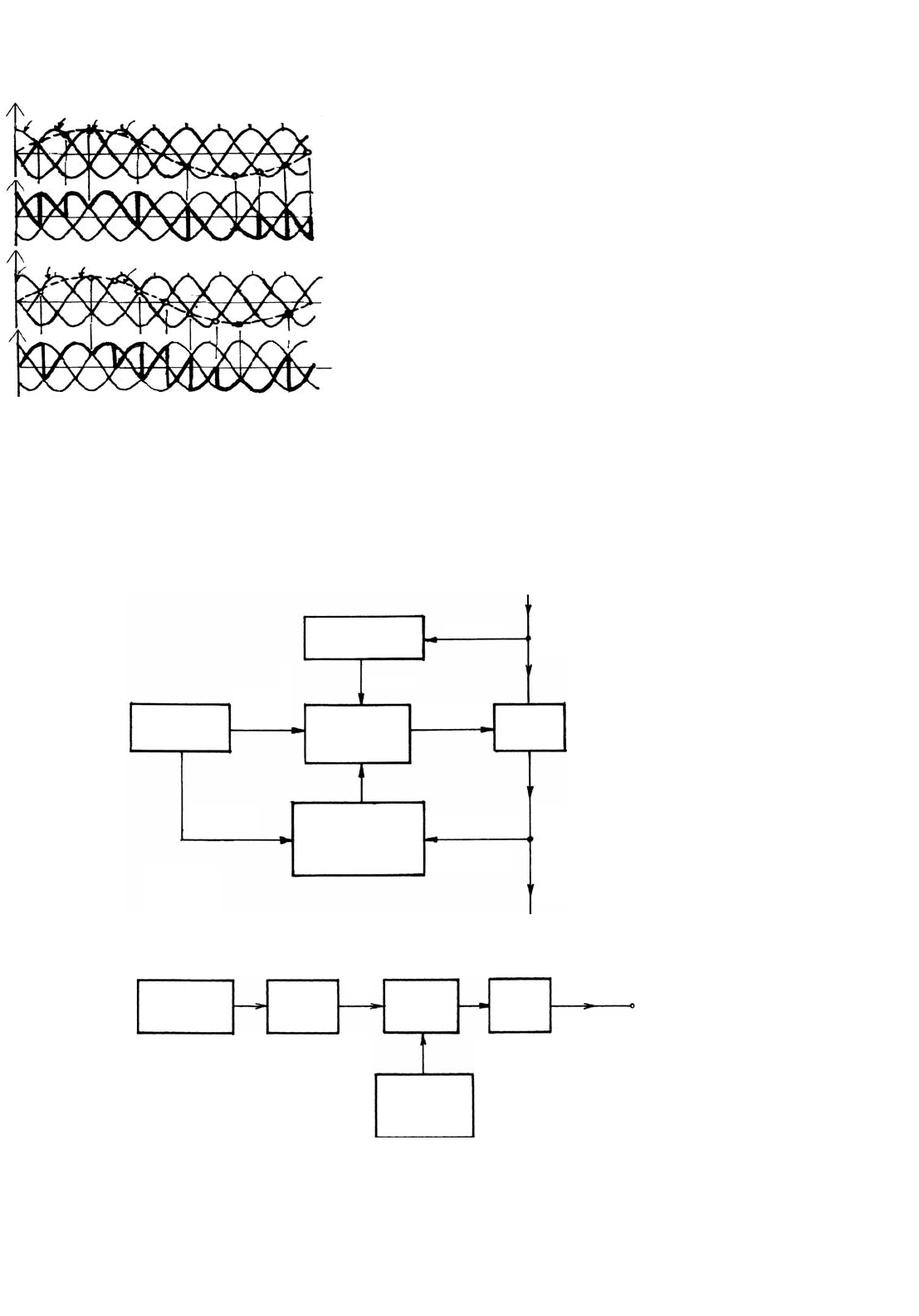
Control Circuit Block Diagram: Figure 18.29 [10] shows a
simplified block diagram of the control circuit for a circu-
lating current-free cycloconverter implemented with ICs in
the early seventies in the Power Electronics Laboratory at IIT
Kharagpur in India. The same circuit is also applicable to
a circulating current cycloconverter with the omission of the
Converter Group Selection and Blanking circuit.
The Synchronizing circuit produces the modulating voltages
(e
a
=−Kv
b
, e
b
=−Kv
c
, e
c
=−Kv
a
), synchronized with the
mains through step-down transformers and proper filter
circuits.
500 A. K. Chattopadhyay
e
a
v
a
v
b
v
c
v
op
v
a
v
b
v
c
v
on
e
b
e
c
e
r
e
a
e
b
e
c
e
r
FIGURE 18.28 Derivation of P-converter and N-converter output
voltages.
Reference
source
Converter
group selection and
blanking circuit
Load current
signal
Load
v
i
3-Phase
variable frequency
output
Logic and
triggering
circuit
Synchronizing
circuit
trigger pulse
3-Phase, 50 Hz
supply
Power
circuit
e
ra’
e
rb’
e
rc
e
ra’
e
rb’
e
rc
e
a’
e
b’
e
c
v
a’
v
b’
v
c
FIGURE 18.29 Block diagram for a circulating current-free cycloconverter control circuit.
UJT
Reflecting
Oscillator
Ring
Counter
Switches
and
Choppers
Filters
L.F. out put
e
ra’
e
rb’
e
rc
Fixed
frequency
sinusoidal
oscillator
FIGURE 18.30 Block diagram of a variable-voltage variable-frequency three-phase reference source.
The Reference Source produces variable voltage variable
frequency reference signal (e
ra
, e
rb
, e
rc
) (three-phase for a
three-phase cycloconverter) for comparison with the modu-
lation voltages. Various ways, analog or digital, have been
developed to implement this reference source as in the case
of the PWM inverter. In one of the early analog schemes
Fig. 18.30 [10], for a three-pulse cycloconverter, a variable-
frequency UJT relaxation oscillator of frequency 6f
d
triggers
a ring counter to produce a three-phase square-wave output
of frequency f
d
which is used to modulate a single-phase fixed
frequency (f
c
) variable amplitude sinusoidal voltage in a three-
phase full-wave transistor chopper. The three-phase output
contains (f
c
−f
d
), (f
c
+f
d
), (3f
d
+f
c
), etc. frequency compo-
nents from where the “wanted” frequency component (f
c
−f
d
)
is filtered out for each phase using a low-pass filter. For exam-
ple, with f
c
= 500 Hz and frequency of the relaxation oscillator
varying between 2820 and 3180 Hz, a three phase 0–30 Hz
reference output can be obtained with the facility for phase
sequence reversal.
The Logic and Trigger Circuit for each phase involves com-
parators for comparison of the reference and modulating
voltages, and inverters acting as buffer stages. The outputs of
the comparators are used to clock the flip-flops or latches

18 AC–AC Converters 501
whose outputs in turn feed the SCR gates through AND gates
and pulse amplifying and isolation circuits, the second input
to the AND gates being from the Converter Group Selection
and Blanking Circuit.
In the Converter Group Selection and Blanking Circuit, the
zero crossing of the current at the end of each half cycle is
detected and is used to regulate the control signals either to
P-group or N-group converters depending on whether the
current goes to zero from negative to positive or positive to
negative, respectively. However, in practice, the current being
discontinuous passes through multiple zero crossings while
changing direction which may lead to undesirable switch-
ing of the converters. So, in addition to the current signal,
the reference voltage signal is also used for the group selec-
tion, and a threshold band is introduced in the current signal
detection to avoid inadvertent switching of the converters.
Further, a delay circuit provides a blanking period of appropri-
ate duration between the converter group switching to avoid
line-to-line short circuits [10]. In some schemes, the delays
are not introduced when a small circulating current is allowed
during cross-over instants limited by reactors of limited size
and this scheme operates in the so called “dual mode” –
circulating current as well as circulating current-free mode
for minor and major portions of the output cycle respec-
tively. A different approach to the converter group selection,
based on the closed-loop control of the output voltage where
a bias voltage is introduced between the voltage transfer char-
acteristics of the converters to reduce circulating current is
discussed in [8].
Improved Control Schemes: With the development of
microprocessors and PC-based systems, digital software
control has taken over many tasks in modern cycloconvert-
ers, particularly in replacing the low-level reference waveform
generation and analog signal comparison units. The reference
waveforms can be easily generated in the computer, stored in
the EPROMs and accessed under the control of a stored pro-
gram and microprocessor clock oscillator. The analog signal
voltages can be converted to digital signals by using analog-
to-digital converters (ADCs). The waveform comparison can
then be made with the comparison features of the micro-
processor system. The addition of time delays and inter-group
blanking can also be achieved with digital techniques and
computer software. A modification of the cosine firing con-
trol, using communication principles like regular sampling in
preference to the natural sampling (discussed so far) of the
reference waveform, yielding a stepped sine wave before com-
parison with the cosine wave [11] has been shown to reduce the
presence of sub-harmonics (discussed later) in the circulating
current-cycloconverter, and facilitate microprocessor-based
implementation, as in the case of PWM inverter.
For a six pulse non-circulating current cycloconverter-
fed synchronous motor drive with a vector control scheme
and a flux observer, a PC-based hybrid control scheme
(a combination of analog and digital control) has been
reported in [12]. Here the functions such as comparison,
group selection, blanking between the groups and triggering
signal generation, filtering and phase conversion are left to the
analog controller and digital controller that takes care of more
serious tasks like voltage decoupling for current regulation,
flux estimation using observer, speed, flux and field current
regulators using PI-controllers, position and speed calcula-
tion leading to an improvement of sampling time and design
accuracy.
18.4.4 Cycloconverter Harmonics and Input
Current Waveform
The exact waveshape of the output voltage of the cyclocon-
verter depends on (i) the pulse number of the converter;
(ii) the ratio of the output to input frequency (f
o
/f
i
); (iii) the
relative level of the output voltage; (iv) load displacement
angle; (v) circulating current or circulating current-free oper-
ation; and (vi) the method of control of the firing instants.
The harmonic spectrum of a cycloconverter output voltage is
different and more complex than that of a phase-controlled
converter. It has been revealed [8] that because of the con-
tinuous “to-and-fro” phase modulation of the converter firing
angles, the harmonic distortion components (known as neces-
sary distortion terms) have frequencies which are sums and
differences between multiples of output and input supply
frequencies.
Circulating Current-free Operation: A derived general
expression for the output voltage of a cycloconverter with
circulating current-free operation [8] shows the following
spectrum of harmonic frequencies for the 3-pulse, 6-pulse,
and 12-pulse cycloconverters employing cosine modulation
technique:
3-pulse: f
oH
=
3(2k − 1)f
i
±2nf
o
and
6kf
i
±(2n +1)f
o
6-pulse: f
oH
=
6kf
i
±(2n +1)f
o
12-pulse: f
oH
=
6kf
i
±(2n +1)f
o
(18.30)
where k is any integer from 1 to infinity and n is any integer
from 0 to infinity.
It may be observed that for certain ratios of f
o
/f
i
, the order
of harmonics may be less or equal to the desired output fre-
quency. All such harmonics are known as sub-harmonics, since
they are not higher multiples of the input frequency. These
sub-harmonics may have considerable amplitudes (e.g. with
a 50 Hz input frequency and 35 Hz output frequency, a sub-
harmonic of frequency 3 ×50 −4 × 35 = 10 Hz is produced
whose magnitude is 12.5% of the 35 Hz component [11]) and
are difficult to filter and so objectionable. Their spectrum

502 A. K. Chattopadhyay
increase with the increase of the ratio f
o
/f
i
and so limits its
value at which a tolerable waveform can be generated.
Circulating-current Operation: For circulating-current oper-
ation with continuous current, the harmonic spectrum in the
output voltage is the same as that of the circulating current-free
operation except that each harmonic family now terminates
at a definite term, rather than having infinite number of
components. They are
3-pulse: f
oH
=
3(2k −1)f
i
±2nf
o
, n ≤3(2k −1)+1
and
6kf
i
±(2n+1)f
o
,(2n+1)≤(6k +1)
6-pulse: f
oH
=
6kf
i
±(2n+1)f
o
,(2n+1)≤(6k +1)
12-pulse: f
oH
=
6kf
i
±(2n+1)f
o
,(2n+1)≤(12k +1)
(18.31)
The amplitude of each harmonic component is a function
of the output voltage ratio for the circulating-current cyclo-
converter and the output voltage ratio as well as the load
displacement angle for the circulating current-free mode.
From the point of view of maximum useful attainable
output-to-input frequency ratio (f
i
/f
o
) with the minimum
amplitude of objectionable harmonic components, a guideline
is available in [8] for it as 0.33, 0.5, and 0.75 for 3-, 6-, and
12-pulse cycloconverter, respectively. However, with the mod-
ification of the cosine wave modulation timings like regular
sampling [11] in the case of circulating-current cycloconverters
only and using a sub-harmonic detection and feedback control
concept [13, 14] for both circulating- and circulating-current-
free cases, the sub-harmonics can be suppressed and useful
frequency range for the naturally commutated cycloconverters
can be increased.
Other Harmonic Distortion Terms: Besides the harmonics
as mentioned, other harmonic distortion terms consisting of
frequencies of integral multiples of desired output frequency
appear, if the transfer characteristic between the output and
reference voltages is not linear. These are called unnecessary
distortion terms which are absent when the output frequen-
cies are much less than the input frequency. Further, some
practical distortion terms may appear due to some practical
non-linearities and imperfections in the control circuits of the
cycloconverter, particularly at relatively lower levels of output
voltage.
Input Current Waveform: Although the load current, par-
ticularly for higher pulse cycloconverters can be assumed to be
sinusoidal, the input current is more complex being made of
pulses. Assuming the cycloconverter to be an ideal switching
circuit without losses, it can be shown from the instantaneous
power balance equation that in cycloconverter supplying a
single-phase load, the input current has harmonic components
of frequencies (f
I
±2f
o
), called characteristic harmonic frequen-
cies which are independent of pulse number and they result
in an oscillatory power transmittal to the ac supply system.
In the case of cycloconverter feeding a balanced three-phase
load, the net instantaneous power is the sum of the three
oscillating instantaneous powers when the resultant power is
constant and the net harmonic component is much reduced
compared to that of a single-phase load case. In general, the
total rms value of the input current waveform consists of three
components: in-phase, quadrature, and the harmonic. The
in-phase component depends on the active power output while
the quadrature component depends on the net average of the
oscillatory firing angle and is always lagging.
18.4.5 Cycloconverter Input Displacement/
Power Factor
The input supply performance of a cycloconverter such as dis-
placement factor or fundamental power factor, input power
factor, and the input current distortion factor are defined sim-
ilar to those of the phase-controlled converter. The harmonic
factor for the case of a cycloconverter is relatively complex as
the harmonic frequencies are not simple multiples of the input
frequency but are sums and differences between multiples of
output and input frequencies.
Irrespective of the nature of the load, leading, lagging, or
unity power factor, the cycloconverter requires reactive power
decided by the average firing angle. At low output voltage,
the average phase displacement between the input current and
the voltage is large and the cycloconverter has a low input
displacement and power factor. Besides load displacement
factor and output voltage ratio, another component of the
reactive current arises due to the modulation of the firing
angle in the fabrication process of the output voltage [8]. In a
phase-controlled converter supplying dc load, the maximum
displacement factor is unity for maximum dc output voltage.
However, in the case of the cycloconverter, the maximum
input displacement factor is 0.843 with unity power factor
load [8, 15]. The displacement factor decreases with reduc-
tion in the output voltage ratio. The distortion factor of the
input current is given by (I
1
/I) which is always less than 1 and
the resultant power factor (= distortion factor ×displacement
factor) is thus much lower (around 0.76 maximum) than the
displacement factor and this is a serious disadvantage of the
naturally commutated cycloconverter (NCC).
18.4.6 Effect of Source Impedance
The source inductance introduces commutation overlap and
affects the external characteristics of a cycloconverter similar
to the case of a phase-controlled converter with the dc out-
put. It introduces delay in transfer of current from one SCR

18 AC–AC Converters 503
to another, results in a voltage loss at the output and a modi-
fied harmonic distortion. At the input, the source impedance
causes “rounding off” of the steep edges of the input cur-
rent waveforms resulting in reduction in the amplitudes of
higher order harmonic terms as well as a decrease in the input
displacement factor.
18.4.7 Simulation Analysis of Cycloconverter
Performance
The non-linearity and discrete time nature of practical cyclo-
converter systems, particularly for discontinuous current con-
ditions make an exact analysis quite complex and a valuable
design and analytical tool is a digital computer simulation of
the system. Two general methods of computer simulation of
the cycloconverter waveforms for RL and induction motor
loads with circulating current and circulating current-free
operation have been suggested in [16] where one of the meth-
ods which is very fast and convenient is the cross-over points
method that gives the cross-over points (intersections of the
modulating and reference waveforms) and the conducting
phase numbers for both P- and N-converters from which
the output waveforms for a particular load can be digitally
computed at any interval of time for a practical cycloconverter.
18.4.8 Power Quality Issues
Degradation of power quality (PQ) in a cycloconverter-fed
system due to sub-harmonics/interharmonics in the input
and the output has been a subject of recent studies [14, 17].
In [17], the study includes the impact of cycloconverter control
strategies on the total harmonic distortion (THD), distribu-
tion transformers, and communication lines while in [14],
the PQ indices are suitably defined and the effect on THD,
input/output displacement factor and input/output power fac-
tor for a cycloconverter-fed synchronous motor drive are stud-
ied together with a development of a simple feedback method
of reduction of subharmonics/low frequency interharmonics
for improvement of the power quality. The implementation
of this scheme, detailed in [14], requires a simple modifica-
tion of the control circuit of the cycloconverter in contrast to
the expensive power level active filters otherwise required for
suppression of such harmonics [18].
18.4.9 Forced Commutated Cycloconverter
The naturally commutated cycloconverter (NCC) with SCRs
as devices, so far discussed, is sometimes referred to as, a
restricted frequency changer as in view of the allowance on
the output voltage quality ratings, the maximum output volt-
age frequency is restricted (f
o
f
i
), as mentioned earlier.
With devices replaced by fully controlled switches like forced
commutated SCRs, power transistors, IGBTs, GTOs, etc.,
a forced commutated cycloconverter can be built where the
desired output frequency is given by f
o
=|f
s
− f
i
|, where
f
s
= switching frequency which may be larger or smaller
than the f
i
. In the case when f
o
≥ f
i
, the converter is called
Unrestricted Frequency Changer (UFC) and when f
o
≤ f
i
,itis
called a Slow Switching Frequency Changer (SSFC). The early
FCC structures have been comprehensively treated in [15].
It has been shown that in contrast with the NCC, when the
input displacement factor (IDF) is always lagging, in UFC it
is leading when the load displacement factor is lagging and
vice versa, and in SSFC, it is identical to that of the load.
Further, with proper control in an FCC, the input displace-
ment factor can be made unity displacement factor frequency
changer (UDFFC) with concurrent composite voltage wave-
form or controllable displacement factor frequency changer
(CDFFC), where P-converter and N-converter voltage seg-
ments can be shifted relative to the output current wave
for control of IDF continuously from lagging via unity to
leading.
In addition to allowing bilateral power flow, UFCs offer an
unlimited output frequency range, offer good input voltage
utilization, do not generate input current and output voltage
sub-harmonics and require only nine bi-directional switches
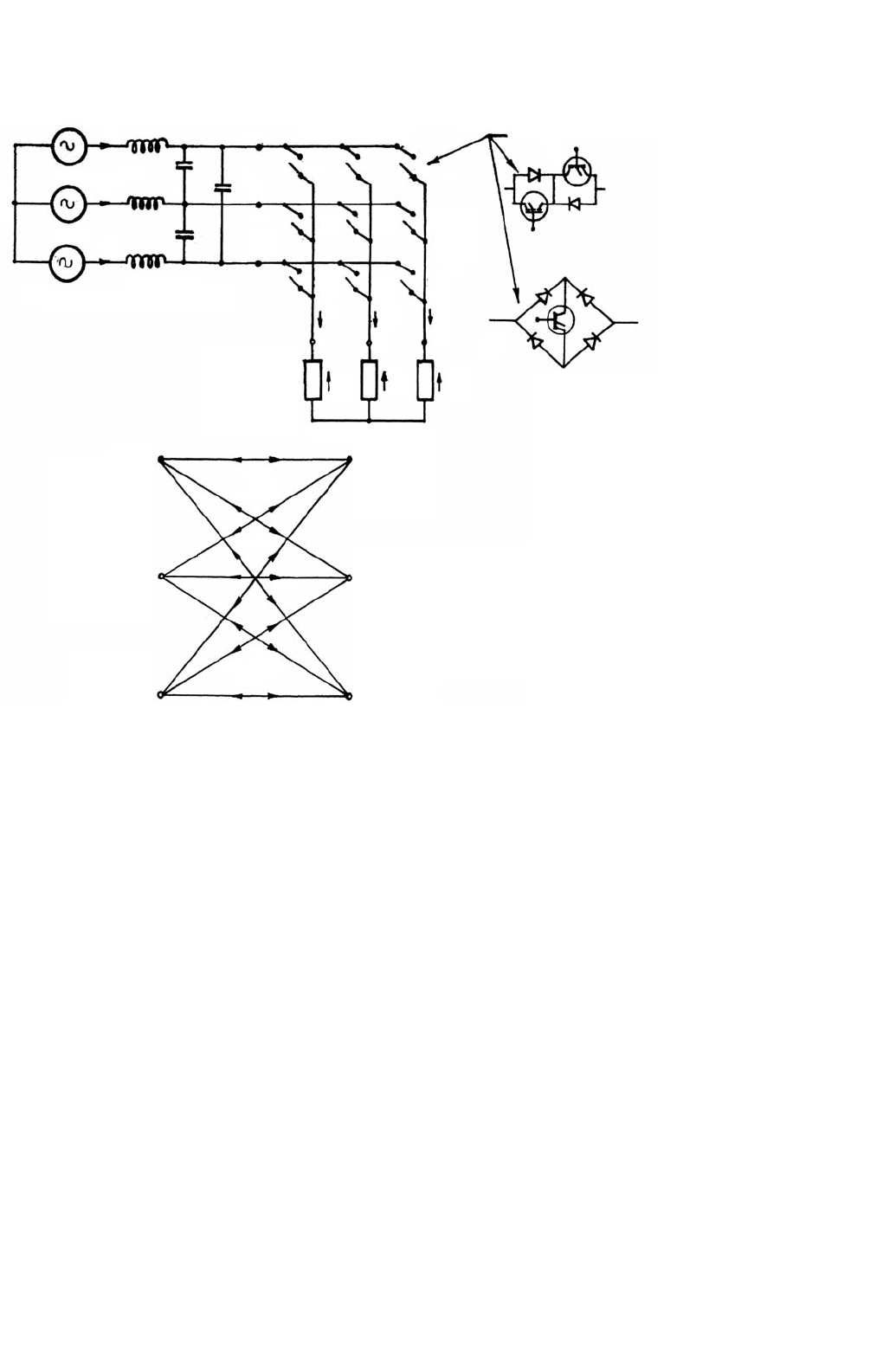
(Fig. 18.31) for a three-phase to three-phase conversion. The
main disadvantage of the structures treated in [15] is that they
generate large unwanted low-order input current and output
voltage harmonics which are difficult to filter out, particu-
larly for low output voltage conditions. This problem has
largely been solved with an introduction of an imaginative
PWM voltage control scheme in [19], which is the basis of the
newly designated converter called the Matrix Converter (also
known as PWM Cycloconverter) which operates as a Gener-
alized Solid-State Transformer with significant improvement
in voltage and input current waveforms resulting in sine-
wave input and sine-wave output as discussed in the next
section.
18.5 Matrix Converter
The matrix converter (MC) is a development of the FCC
based on bi-directional fully controlled switches, incorporating
PWM voltage control, as mentioned earlier. With the initial
progress made by Venturini [19–21], it has received consider-
able attention in recent years as it provides a good alternative to
the double-sided PWM voltage source rectifier– inverters hav-
ing the advantages of being a single stage converter with only
nine switches for three-phase to three-phase conversion and
inherent bi-directional power flow, sinusoidal input/output
waveforms with moderate switching frequency, possibility of
a compact design due to the absence of dc link reactive
components, and controllable input power factor indepen-
dent of the output load current. The main disadvantages
of the matrix converters developed so far are the inherent
504 A. K. Chattopadhyay
Input Filter
i
B
i
A
A
S
Aa
S
Ab
S
Ac
S
Ca
V
an
V
bn
V
cn
i
a
a
M
bc
i
b
i
c
S
Cb
S
Cc
S
Ba
S
Bb
S
Bc
Matrix Converter
Bidirectional Switches
B
C
0
(a)
(b)
V
CO
V
BO
V
AO
V
Co
V
Bo
V
Ao
V
an
S
Aa
S
Ba
S
Ac
S
Ca
S
Bb
S
Cb
S
Bc
S
Cc
S
Ab
V
bn
V
Cn
i
C
3-Φ
Inductive
Load
3-φ Input
FIGURE 18.31 (a) 3φ-3φ Matrix converter (forced commutated cycloconverter) circuit with input filter and (b) switching matrix symbol for
converter in (a).
restriction of the voltage transfer ratio (0.866), a more com-
plex control, commutation and protection strategy, and above
all the non-availability of a fully controlled bi-directional high
frequency switch integrated in a silicon chip (triac, though
bilateral, cannot be fully controlled).
The power circuit diagram of the most practical three-
phase to three-phase (3φ–3φ) matrix converter is shown in
Fig. 18.31a which uses nine bi-directional switches so arranged
that any of the three input phases can be connected to any
output phase as shown in the switching matrix symbol in
Fig. 18.31b. Thus, the voltage at any input terminal may be
made to appear at any output terminal or terminals while
the current in any phase of the load may be drawn from
any phase or phases of the input supply. For the switches,
the inverse-parallel combination of reverse-blocking self-
controlled devices like power MOSFETs or IGBTs or transistor
embedded diode bridge as shown have been used so far. New
perspective configuration of the bi-directional switch is to use
two RB-IGBTs with reverse blocking capability in anti-parallel,
eliminating the diodes reducing the conducting losses in the
converter significantly. The circuit is called a matrix converter
as it provides exactly one switch for each of the possible con-
nections between the input and the output. The switches
should be controlled in such a way that, at any time, one
and only one of the three switches connected to an output
phase must be closed to prevent “short circuiting” of the sup-
ply lines or interrupting the load current flow in an inductive
load. With these constraints, it can be visualized that out of
the possible 512 (= 2
9
) states of the converter, only 27 switch
combinations are allowed as given in Table 18.1 which includes
the resulting output line voltages and input phase currents.
These combinations are divided into three groups. Group-I
consists of six combinations when each output phase is con-
nected to a different input phase. In Group-II, there are three
subgroups each having six combinations with two output
phases short-circuited (connected to the same input phase).
Group-III includes three combinations with all output phases
short-circuited.
With a given set of input three-phase voltages, any desired
set of three-phase output voltages can be synthesized by

18 AC–AC Converters 505
TABLE 18.1 Three-phase/three-phase matrix converter switching combinations
Group a b c v
ab
v
bc
v
ca
i
A
i
B
i
C
S
Aa
S
Ab
S
Ac
S
Ba
S
Bb
S
Bc
S
Ca
S
Cb
S
Cc
ABCv
AB
v
BC
v
CA
i
a
i
b
i
c
100010001
ACB−v
CA
−v
BC
−v
AB
i
a
i
c
i
b
100001010
BAC−v
AB
−v
CA
−v
BC
i
b
i
a
i
c
010100001
IBCAv
BC
v
CA
v
AB
i
c
i
a
i
b
010001010
CABv
CA
v
AB
v
BC
i
b
i
c
i
a
001100010
CBA−v
BC
−v
AB
−v
CA
i
c
i
b
i
a
001010100
ACC−v
CA
0 v
CA
i
a
0 −i
a
100001001
BCCv
BC
0 −v
BC
0 i
a
−i
a
010001001
BAA−v
AB
0 −v
AB
−i
a
i
a
0010100100
II-A C A A v
CA
0 −v
CA
−i
a
0 i
a
001100100
CBB−v
BC
0 v
BC
0 −i
a
i
a
001010010
ABBv
AB
0 −v
AB
i
a
−i
a
0100010010
CAC−v
CA
−v
CA
0 i
b
0 −i
b
001100001
CBC−v
BC
v
BC
00i
b
−i
b
001010001
ABAv
AB
−v
AB
0 −i
b
i
b
0100010100
II-B A C A −v
CA
v
CA
0 −i
b
0 i
b
100001100
BCBv
BC
−v
BC
00−i
b
i
b
010001010
BAB−v
AB
v
AB
0 i
b
−i
b
0010100010
CCA0 v
CA
−v
CA
i
c
0 −i
c
001001100
CCB0 −v
BC
v
BC
0 i
c
−i
c
001001010
AAB0 v
AB
−v
AB
−i
c
i
c
0100100010
II-C A A C 0 −v
CA
v
CA
−i
c
0 i
c
100100001
BBC0 v
BC
−v
BC
0 −i
c
i
c
010010001
BBA0 −v
AB
v
AB
i
c
−i
c
0010010100
AAA0 0 0 000000100100
III BBB0 0 0 000000010010
CCC0 0 0 000000001001
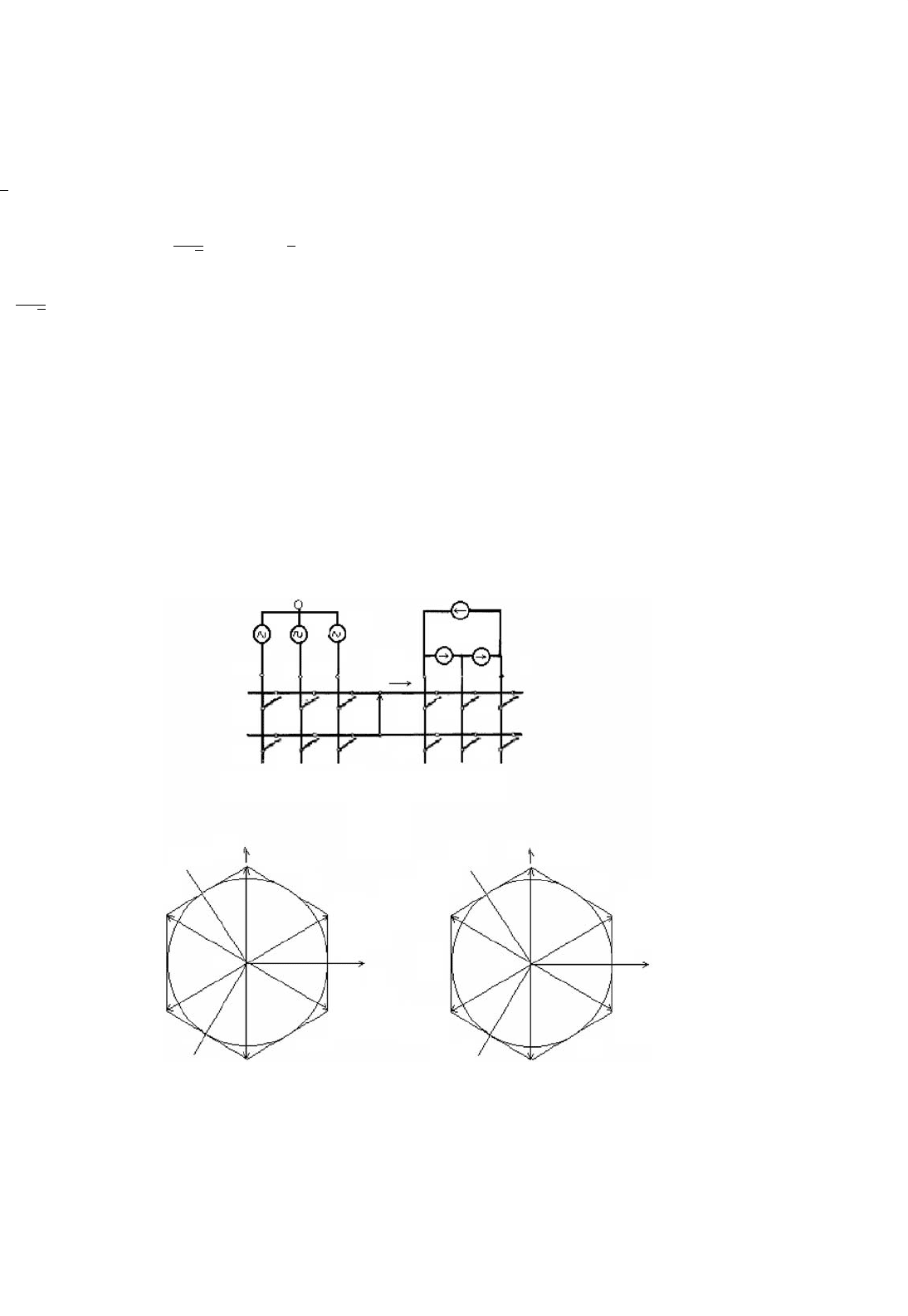
adopting a suitable switching strategy. However, it has been
shown [21, 22] that regardless of the switching strategy, there
are physical limits on the achievable output voltage with these
converters as the maximum peak-to-peak output voltage can-
not be greater than the minimum voltage difference between
two phases of the input. To have complete control of the
synthesized output voltage, the envelope of the three-phase
reference or target voltages must be fully contained within
the continuous envelope of the three-phase input voltages.
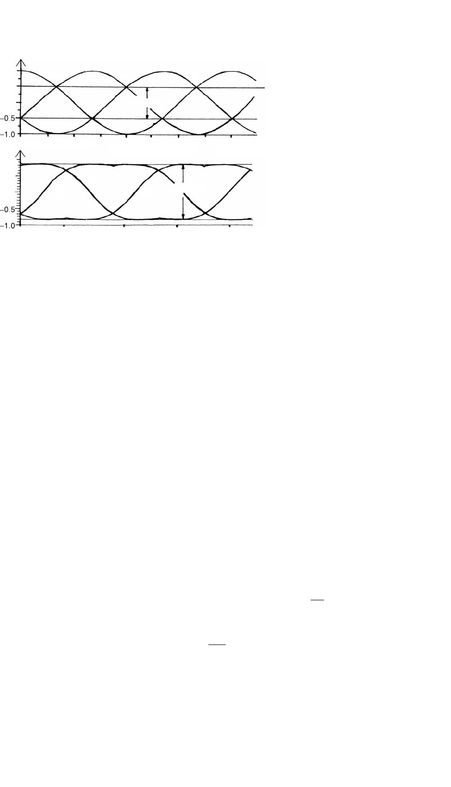
Initial strategy with the output frequency voltages as refer-
ences reported the limit as 0.5 of the input as shown in
Fig. 18.32a. This can be increased to 0.866 by adding a third
harmonic voltage of input frequency (V
i
/4) · cos 3ω
i
t to all
target output voltages and subtracting from them a third har-
monic voltage of output frequency (V
o
/6) · cos 3ω
o
t as shown
in Fig. 18.32b [21, 22]. However, this process involves con-
siderable amount of additional computations in synthesizing
the output voltages. The other alternative is to use the space
vector modulation (SVM) strategy as used in PWM inverters
without adding third harmonic components but it also yields
the maximum voltage transfer ratio as 0.866.
An ac input LC filter is used to eliminate the switching
ripples generated in the converter and the load is assumed to
be sufficiently inductive to maintain continuity of the output
currents.
18.5.1 Operation and Control of the
Matrix Converter
The converter in Fig. 18.31 connects any input phase (A, B,
and C) to any output phase (a, b, and c) at any instant. When
connected, the voltages v
an
, v
bn
, v
cn
at the output terminals
are related to the input voltages V
Ao
, V
Bo
, V
Co
as
v
an
v
bn
v
cn
=
S
Aa
S
Ba
S
Ca
S
Ab
S
Bb
S
Cb
S
Ac
S
Bc
S
Cc
v
Ao
v
Bo
v
Co
(18.32)
where S
Aa
through S
Cc
are the switching variables of the corre-
sponding switches shown in Fig. 18.31. For a balanced linear
star-connected load at the output terminals, the input phase
currents are related to the output phase currents by
i
A
i
B
i
C
=
S
Aa
S
Ab
S
Ac
S
Ba
S
Bb
S
Bc
S
Ca
S
Cb
S
Cc
i
a
i
b
i
c
(18.33)
506 A. K. Chattopadhyay
V
an
V
an
V
bn
V
cn
V
in
1.0
0.5
0.0
1.0
0.5
0.0
0 90 180
0.5
(a)
(b)
270 360
0 90 180 270 360
′
V
cn
′
V
bn
′
0.866 V
in
FIGURE 18.32 Output voltage limits for three-phase ac-ac matrix converter: (a) basic converter input voltages and (b) maximum attainable with
inclusion of third harmonic voltages of input and output frequency to the target voltages.
Note that the matrix of the switching variables in Eq. (18.33) is
a transpose of the respective matrix in Eq. (18.32). The matrix
converter should be controlled using a specific and appropri-
ately timed sequence of the values of the switching variables,
which will result in balanced output voltages having the desired
frequency and amplitude, while the input currents are bal-
anced and in phase (for unity IDF) or at an arbitrary angle
(for controllable IDF) with respect to the input voltages. As
the matrix converter, in theory, can operate at any frequency,
at the output or input, including zero, it can be employed
as a three-phase ac–dc converter, dc/3-phase ac converter, or
even a buck/boost dc chopper and thus as a universal power
converter.
The control methods adopted so far for the matrix converter
are quite complex and are subjects of continuing research
[21–38]. Out of several methods proposed for independent
control of the output voltages and input currents, two meth-
ods are of wide use and will be briefly reviewed here: (i) the
Venturini method based on a mathematical approach of trans-
fer function analysis and (ii) the Space Vector Modulation
(SVM) approach (as has been standardized now in the case
of PWM control of the dc link inverter).
Venturini Method: Given a set of three-phase input volt-
ages with constant amplitude V
i
and frequency f
i
= ω
i
/2π,
this method calculates a switching function involving the duty
cycles of each of the nine bi-directional switches and generate
the three-phase output voltages by sequential piecewise sam-
pling of the input waveforms. These output voltages follow
a predetermined set of reference or target voltage waveforms
and with a three-phase load connected, a set of input currents
I
i
and angular frequency ω
i
should be in phase for unity IDF
or at a specific angle for controlled IDF.
A transfer function approach is employed in [29] to achieve
the above mentioned features by relating the input and output
voltages and the output and input currents as
V
o1
(t)
V
o2
(t)
V
o3
(t)
=
m
11
(t) m
12
(t) m
13
(t)
m
21
(t) m
22
(t) m
23
(t)
m
31
(t) m
32
(t) m
33
(t)
V
i1
(t)
V
i2
(t)
V
i3
(t)
(18.34)
I
i1
(t)
I
i2
(t)
I
i3
(t)
=
m
11
(t) m
21
(t) m
31
(t)
m
12
(t) m
22
(t) m
32
(t)
m
13
(t) m
23
(t) m
33
(t)
I
o1
(t)
I
o2
(t)
I
o3
(t)
(18.35)
where the elements of the modulation matrix, m
ij
(t)(i, j =
1, 2, 3) represent the duty cycles of a switch connecting output
phase i to input phase j within a sample switching interval.
The elements of m
ij
(t) are limited by the constraints
0 ≤ m
ij
(t) ≤ 1 and
3
j=1
m
ij
(t) = 1(i = 1, 2, 3)
The set of three-phase target or reference voltages to achieve
the maximum voltage transfer ratio for unity IDF is
V
o1
(t)
V
o2
(t)
V
o3
(t)
= V
om
cos ω
o
t
cos(ω
o
t −120
◦
)
cos(ω
o
t −240
◦
)
+
v
im
4
cos(3ω
i
t)
cos(3ω
i
t)
cos(3ω
i
t)
−
V
om
6
cos(3ω
o
t)
cos(3ω
o
t)
cos(3ω
o
t)
(18.36)
where V
om
and V
im
are the magnitudes of output and
input fundamental voltages of angular frequencies ω
o
and ω
i
,
18 AC–AC Converters 507
respectively. With V
om
≤ 0.866 V
im
, a general formula for the
duty cycles m
ij
(t) is derived in [29]. For unity IDF condition,
a simplified formula is
m
ij
=
1
3
1+2qcos(ω
1
t −2(j −1)60
◦
)
cos(ω
o
t −2(i −1)60
◦
)+
1
2
√
3
cos(3ω
i
t)−
1
6
cos(3ω
o
t)
−
2q
3
√
3
cos(4ω
i
t −2(j −1)60
◦
)
−cos(2ω
i
t −2(1−j)60
◦
)
(18.37)
where i, j = 1, 2, 3 and q = V
om
/V
im
.
The method developed as above is based on a Direct Trans-
fer Function (DTF) approach using a single modulation matrix
for the matrix converter, employing the switching combina-
tions of all the three groups in Table 18.1. Another approach
called Indirect Transfer Function (ITF) approach [23, 24] con-
siders the matrix converter as a combination of PWM voltage
source rectifier–PWM voltage source inverter (VSR–VSI) and
V
AO
V
BO
V
CO
ABC
O
S
pA
S
nA
V
bc
V
ca
Vo (p,p,n) or (n,n,p)
V
o
V
V
3
(n,p,n)
V
4
(n,p,p)
V
ab
V
dc
V
2
(p,p,n)
i
B
i
C
i
A
I
3
(B,A) I
1
(A,C)
I
6
(A,B)I
4
(C,A)
I
5
(C,B)
I
2
(B,C)
V
1
(p,n,n)
S
nB
S
nC
S
an
S
ap
S
bp
S
cp
S
bn
S
cn
S
pB
S
pC
V
pn
i
ab
i
ca
i
bc
i
p
a
Rectifier
stage
Im Im
Io (A,A) or (B,B) or (C,C)
Re
Io
Re
III
IV
VI
I
II III
IV
VVI
II
Inverter
stage
bc
p
n
(a)
V
6
(p,n,p)
V
5
(n,n,p)
sector
+++
(c)(b)
FIGURE 18.33 Indirect modulation model of a matrix converter: (a) VSR–VSI conversion; (b) output voltage switching vector hexagon; and
(c) input current switching vector hexagon.
employs the already well established VSR and VSI PWM
techniques for MC control utilizing the switching combina-
tions of Group-II and Group-III only of Table 18.1. The draw-
back of this approach is that the IDF is limited to unity and
the method also generates higher and fractional harmonic
components in the input and the output waveforms.
SVM Method: The space vector modulation is a well doc-
umented inverter PWM control technique which yields high
voltage gain and less harmonic distortion compared to the
other modulation techniques. Here, the three-phase input
currents and output voltages are represented as space vec-
tors and SVM is simultaneously applied to the output voltage
and input current space vectors, while the matrix converter is
modeled as a rectifying and inverting stage by the indirect mod-
ulation method (Fig. 18.33). Applications of SVM algorithm
to control of matrix converters have appeared extensively in
the literature [27–37] and shown to have inherent capabil-
ity to achieve full control of the instantaneous output voltage
vector and the instantaneous current displacement angle even
under supply voltage disturbances. The algorithm is based
on the concept that the MC output line voltages for each

508 A. K. Chattopadhyay
switching combination can be represented as a voltage space
vector defined by
v
o
=
2
3
v
ab
+v
bc
exp(j120
◦
) +v
ca
exp(−j120
◦
)
(18.38)
Out of the three groups in Table 18.1, only the switching com-
binations of Group-II and Group-III are employed for the
SVM method. Group-II consists of switching state voltage
vectors having constant angular positions and are called active
or stationary vectors. Each sub-group of Group-II determines
the position of the resulting output voltage space vector and
the six state space voltage vectors form a six-sextant hexagon
used to synthesize the desired output voltage vector. Group-III
comprises the zero vectors positioned at the center of the out-
put voltage hexagon and these are suitably combined with the
active vectors for the output voltage synthesis.
The modulation method involves selection of the vectors
and their on-time computation. At each sampling period T
s
,
the algorithm selects four active vectors related to any possi-
ble combinations of output voltage and input current sectors
in addition to the zero vector to construct a desired reference
voltage. The amplitude and the phase angle of the reference
voltage vector are calculated and the desired phase angle of the
input current vector are determined in advance. For compu-
tation of the on-time periods of the chosen vectors, these are
combined into two sets leading to two new vectors adjacent to
the reference voltage vector in the sextant and having the same
direction as the reference voltage vector. Applying the stan-
dard SVM theory, the general formulae derived for the vector
on-times which satisfy, at the same time, the reference output
voltage and input current displacement angle in [29] are
t
1
=
2qT
s
√
3 cos φi
sin(60
◦
−θ
o
) ·sin(60
◦
−θ
i
)
t
2
=
2qT
s
√
3 cos φ
i
sin(60
◦
−θ
o
) ·sin θ
i
t
3
=
2qT
s
√
3 cos φ
i
sin θ
o
·sin(60
◦
−θ
i
)
t
4
=
2qT
s
√
3 cos φ
i
sin θ
o
·sin θ
i
(18.39)
where q = voltage transfer ratio, φ
i
is the input displacement
angle chosen to achieve the desired input power factor (with
φ
i
= 0, a maximum value of q = 0.866 is obtained), θ
o
and θ
i
are the phase displacement angles of the output voltage and
input current vectors, respectively, whose values are limited
within the 0–60
◦
range. The on-time of the zero vector is
t
o
= T
s
−
4
i=1
t
i
(18.40)
The integral value of the reference vector is calculated over
one sample time interval as the sum of the products of the
two adjacent vectors and their on-time ratios and the process
is repeated at every sample instant.
Control Implementation and Comparison of the Two
Methods: Both the methods need a digital signal proces-
sor (DSP) based system for their implementation. In one
scheme [29] for the Venturini method, the programmable
timers, as available, are used to time out the PWM gating sig-
nals. The processor calculates the six switch duty cycles in each
sampling interval, converts them to integer counts and stores
them in the memory for the next sampling period. In the
SVM method, an erasable programmable read only memory
(EPROM) is used to store the selected sets of active and zero
vectors and the DSP calculates the on-times of the vectors.
Then, with an identical procedure as in the other method, the
timers are loaded with the vector on-times to generate PWM
waveforms through suitable output ports. The total compu-
tation time of the DSP for the SVM method has been found
to be much less that of the Venturini method. Comparison
of the two schemes shows that while in the SVM method the
switching losses are lower, the Venturini method shows bet-
ter performance in terms of input current and output voltage
harmonics.
A direct control method as used in conjunction with the
voltage source converters has been developed recently and
implemented with a 10 kVA matrix converter [38].
18.5.2 Commutation and Protection Issues in a
Matrix Converter
As the matrix converter has no dc link energy storage, any
disturbance in the input supply voltage will affect the out-
put voltage immediately and a proper protection mechanism
has to be incorporated, particularly against over-voltage from
the supply and over-current in the load side. As mentioned,
two types of bi-directional switch configurations have hith-
erto been used, one, the transistor (now IGBT) embedded in a
diode bridge and the other, the two IGBTs in anti-parallel with
reverse voltage blocking diodes. (shown in Fig. 18.31) In the
latter configuration, each diode and IGBT combination oper-
ates in two quadrants only which eliminates the circulating
currents otherwise built up in the diode bridge configuration
that can be limited by only bulky commutation inductors in
the lines.
Commutation: The MC does not contain freewheeling diodes
which usually achieve safe commutation in the case of other
converters. To maintain the continuity of the output current
as each switch turns off, the next switch in sequence must
be immediately turned on. In practice, with bi-directional
switches, a momentary short circuit may develop between the
input phases when the switches cross-over and one solution is