Power electronic handbook
Подождите немного. Документ загружается.

41 Computer Simulation of Power Electronics and Motor Drives 1139
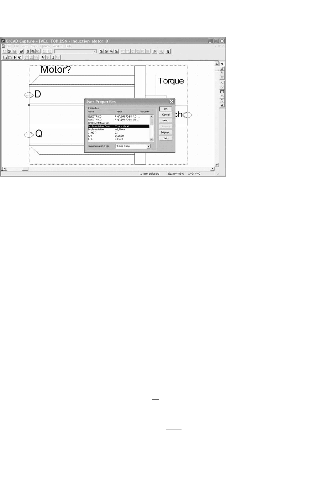
FIGURE 41.20 Screen view of symbol editor with user properties input window.
The attributes, that create the netlist entries, which insert the
previously discussed model for the motor are entered here.
A complete list of all attributes, extracted from a working
example, is given in Table 41.3. Therefore, the reader should
be able to enter the attributes exactly as printed and obtain a
working model.
According to Table 41.3, the value for the TEMPLATE
attribute is as follows:
TEMPLATE = @ElectricD\n\n@ElectricQ\n\n@Mechanical
This statement will insert the expression for “ElectricD,”
i.e. the T-equivalent circuit for the D-axis, two carriage
returns “\n\n,” the expression for “ElectricQ,” i.e. the
T-equivalent circuit for the Q-axis, two more carriage returns
“\n\n,” and finally the expression for “Mechanical,” i.e.
the mechanical model into the netlist. The expressions for
“ElectricD,” “ElectricQ,” and “Mechanical” are defined in
separate attributes. Careful examination of the values of the
“ElectricD,” “ElectricQ,” and “Mechanical” attributes reveals
a number of repetitive terms. The meaning of these terms are
explained below:
@Name – Substitutes what is defined for “@Name” at
the current place.
∧
@REFDES – Inserts the path “
∧
” and the reference desig-
nator “@REFDES” to create a unique node or
part name, that does not repeat. The path is the
concatenation of the names of the symbols and
subcircuits in the hierarchy above the part. The
reference designator is the name of the part on
a particular schematic page.
\n – new line (carriage return) is inserted into the
netlist, however the value of the attribute does
not have a carriage return in it. This means
everything listed after “ElectricD” until “Elec-
tricQ” goes on one line. If the symbol definition
is printed however, it is shown as in Table 41.3.
\n+ – new line and continuation of expression.
\n++ – new line, continuation of expression, numer-
ical operator “+.”
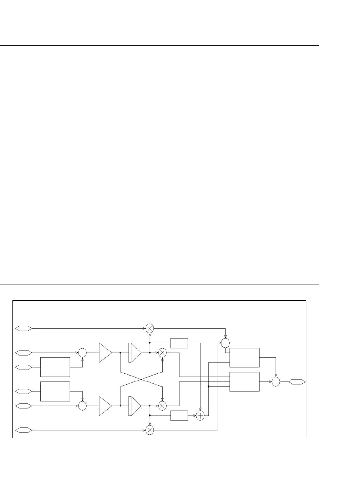
Figure 41.21 shows a subcircuit for the speed observer. This
schematic shows the structure and all the details of the imple-
mentation in the form of a block diagram. The speed observer
uses the stator voltages and currents for the D- and the Q-axis
as input variables. After subtracting the voltage drop across
the winding resistance and the leakage inductance of the sta-
tor from the stator input voltage and scaling the result by
L
r
/L
m
, the observer calculates the D and Q components of the
rotor flux by integration. Since the input values are in the sta-
tionary reference frame, so are the results. The observer also
calculates the magnitude of the rotor flux (Eq. (41.9)) and
then calculates the synchronous angular velocity (Eq. (41.10))
by evaluating the rate of change of the ratio of the D and Q
components. The mathematical relationships are given by the
Eqs. (41.9) and 41.10 [2].
p
λ
rd
λ
rq
=
L
r
L
m
V
sd
V
sq
−
R
s
+σL
s
p 0
0 R
s
+σL
s
p
I
sd
I
sq
σ =
1 −
L
2
m
(
L
r
L
s
)
σ = Leakage factor
(41.9)
1140 M. Giesselmann
TABLE 41.3 List of all attributes used for the self-contained induction motor symbol
Attributes:
REFDES = Motor?
PART = Ind_Motor
MODEL = Ind_Motor
TEMPLATE = @ElectricD\n\n @ElectricQ\n\n@Mechanical
R_Stat = 0.48
R_Rot = 0.358
Lm = 51.25mH
Lsl = 2.18mH
Lrl = 2.89mH
J_mot = 0.1
Omega_init = 0.0
Poles = 4
ElectricD = Rsd
∧
@REFDES %D 1
∧
@REFDES @R_Stat
\nLsld
∧
@REFDES 1
∧
@REFDES Vmd
∧
@REFDES @Lsl
\nLmd
∧
@REFDES Vmd
∧
@REFDES 0 @Lm
\nLrld
∧
@REFDES Vmd
∧
@REFDES 2
∧
@REFDES @Lrl
\nRrd
∧
@REFDES 2
∧
@REFDES ErotD
∧
@REFDES @R_Rot
\nErotd
∧
@REFDES ErotD
∧
@REFDES 0 VALUE {-(Ome
∧
@REFDES)
∗
((V(%Q,3
∧
@REFDES)/@R_Stat)
∗
@Lm
\n++(V(ErotQ
∧
@REFDES,4
∧
@REFDES)/@R_Rot)
∗
(@Lm+@Lrl)) }
ElectricQ=Rsq
∧
@REFDES %Q 3
∧
@REFDES @R_Stat
\nLslq
∧
@REFDES 3
∧
@REFDES Vmq
∧
@REFDES @Lsl
\nLmq
∧
@REFDES Vmq
∧
@REFDES 0 @Lm
\nLrlq
∧
@REFDES Vmq
∧
@REFDES 4
∧
@REFDES @Lrl
\nRrq
∧
@REFDES 4
∧
@REFDES ErotQ
∧
@REFDES @R_Rot
\nErotq
∧
@REFDES ErotQ
∧
@REFDES 0 VALUE {V(Ome
∧
@REFDES)
∗
((V(%D,1
∧
@REFDES)/@R_Stat)
∗
@Lm
\n++(V(ErotD
∧
@REFDES,2
∧
@REFDES)/@R_Rot)
∗
(@Lm+@Lrl)) }
Mechanical=ETorque
∧
@REFDES %Torque 0
\n+ VALUE { (1.5
∗
@Lm
∗
@Poles/2)
∗
(
\n+ ((V(%Q,3
∧
@REFDES)/@R_Stat)
∗
(V(ErotD
∧
@REFDES,2
∧
@REFDES)/@R_Rot)) -
\n+ ((V(%D,1
∧
@REFDES)/@R_Stat)
∗
(V(ErotQ
∧
@REFDES,4
∧
@REFDES)/@R_Rot)) ) }
\nEOme
∧
@REFDES Ome
∧
@REFDES 0 VALUE { V(Om
∧
@REFDES)
∗
@Poles/2 }
\nVLd
∧
@REFDES Om
∧
@REFDES %Omech 0V \nEom
∧
@REFDES Om
∧
@REFDES 0 VALUE {SDT(( V(%Torque)-I(VLd
∧
@REFDES) )/@J_mot) +
@Omega_init }
l_q
V_d
I_d
I_q
V_q
I_d
Open Loop Speed Observer
{@LR/@LM}
{@LR/@LM}
1.0
1.0
0v
0v
PWR2
PWR2
V(%IN1)*
(@LM
/@TAU_R)
/(V(%IN2+1u))
V(%IN)*
@R_STAT+
DDT(V(%IN))*
@LS*@SIGMA
V(%IN)*
@R_STAT+
DDT(V(%IN))*
@LS*@SIGMA
(V(%IN1)–
V(%IN2))
/
(V(%IN3)+1u)
+
−
+
−
OM_e
+
−
+
−
FIGURE 41.21 Subcircuit for speed observer for sensorless vector controller.

41 Computer Simulation of Power Electronics and Motor Drives 1141
TABLE 41.4 List of all attributes for the speed observer symbol
Attributes:
REFDES = Speed_Observer?
PART = Speed_Obs
MODEL = Speed_Obs
TEMPLATE = Ed
∧
@REFDES %Psi_d 0 VALUE { @EXP_d1
\n+ @EXP_d2 \n+ @EXP_d3 }
\nEq
∧
@REFDES %Psi_q 0 VALUE { @EXP_q1
\n+ @EXP_q2 \n+ @EXP_q3 }
\nEmag
∧
@REFDES %Psi_mag 0 VALUE { V(%Psi_d)
∗
V(%Psi_d) + V(%Psi_q)
∗
V(%Psi_q) }
\nExr
∧
@REFDES %Psi_xr 0 VALUE { @EXP_x1
\n+ @EXP_x2 \n+ @EXP_x3 \n+ @EXP_x4 }
\nEOmSync
∧
@REFDES %OmSync 0 VALUE { @EXP_om1 }
SIMULATIONONLY =
EXP_d1 = @Ini_d +
EXP_d2 = SDT( (@Lr/@Lm)
∗
( V(%V_d) - V(%I_sd)
∗
@R_Stat
EXP_d3 = -DDT(V(%I_sd))
∗
@Ls
∗
@Sigma))
EXP_q1 = @Ini_q +
EXP_q2 = SDT( (@Lr/@Lm)
∗
( V(%V_q) - V(%I_sq)
∗
@R_Stat
EXP_q3 = -DDT(V(%I_sq))
∗
@Ls
∗
@Sigma))
Ini_d = 0.0V
Ini_q = 0.0V
EXP_x1 = ( V(%Psi_d)
∗
(@Lr/@Lm)
∗
EXP_x2 = ( V(%V_q) - V(%I_sq)
∗
@R_Stat - DDT(V(%I_sq))
∗
@Ls
∗
@Sigma))
EXP_x3 = -( V(%Psi_q)
∗
(@Lr/@Lm)
∗
EXP_x4 = ( V(%V_d) - V(%I_sd)
∗
@R_Stat - DDT(V(%I_sd))
∗
@Ls
∗
@Sigma))
EXP_om1 = ( V(%Psi_xr) / (V(%Psi_mag)+1u))
d
dt
atan
λ
rq
(
t
)
λ
rd
(
t
)
=ω
s
=
d
dt
λ
rq
(
t
)
λ
rd
(
t
)
−λ
rq
(
t
)
d
dt
λ
rd
(
t
)
λ
rd
(
t
)
2
+λ
rq
(
t
)
2
(41.10)
Since the observer shown in Fig. 41.21 has a large number
of elements, this subcircuit has also been integrated into a
custom part by creating an appropriate TEMPLATE and other
supporting attributes. A complete listing, which was extracted
from thoroughly tested part, is given in Table 41.4. Using this
table, the reader should be able to create this very complex
part with relative ease.
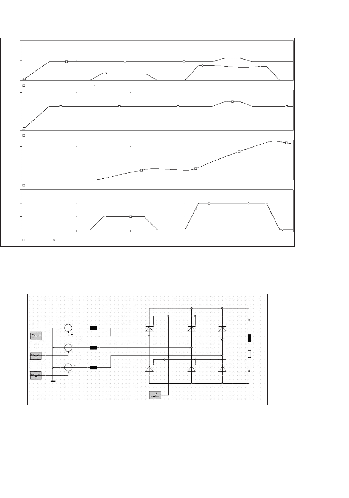
Figure 41.22 shows the output for the speed sensorless
vector control project as it presents itself in the PSpice
9.1/ORCAD evaluation version.
A comparison of the traces for the torque and the torque
command (they are perfectly on top of each other) shows that
the scheme works extremely well. It even works for a start
from zero speed, which is typically not the case in real systems.
The reason is, that the uncertainties of the winding resistance
values (note that they change with temperature) create errors
in observers like this one. The problem is worst at low speeds,
because at low speeds and associated low stator frequencies,
the uncertain winding resistance represents the largest part of
the total machine impedance.
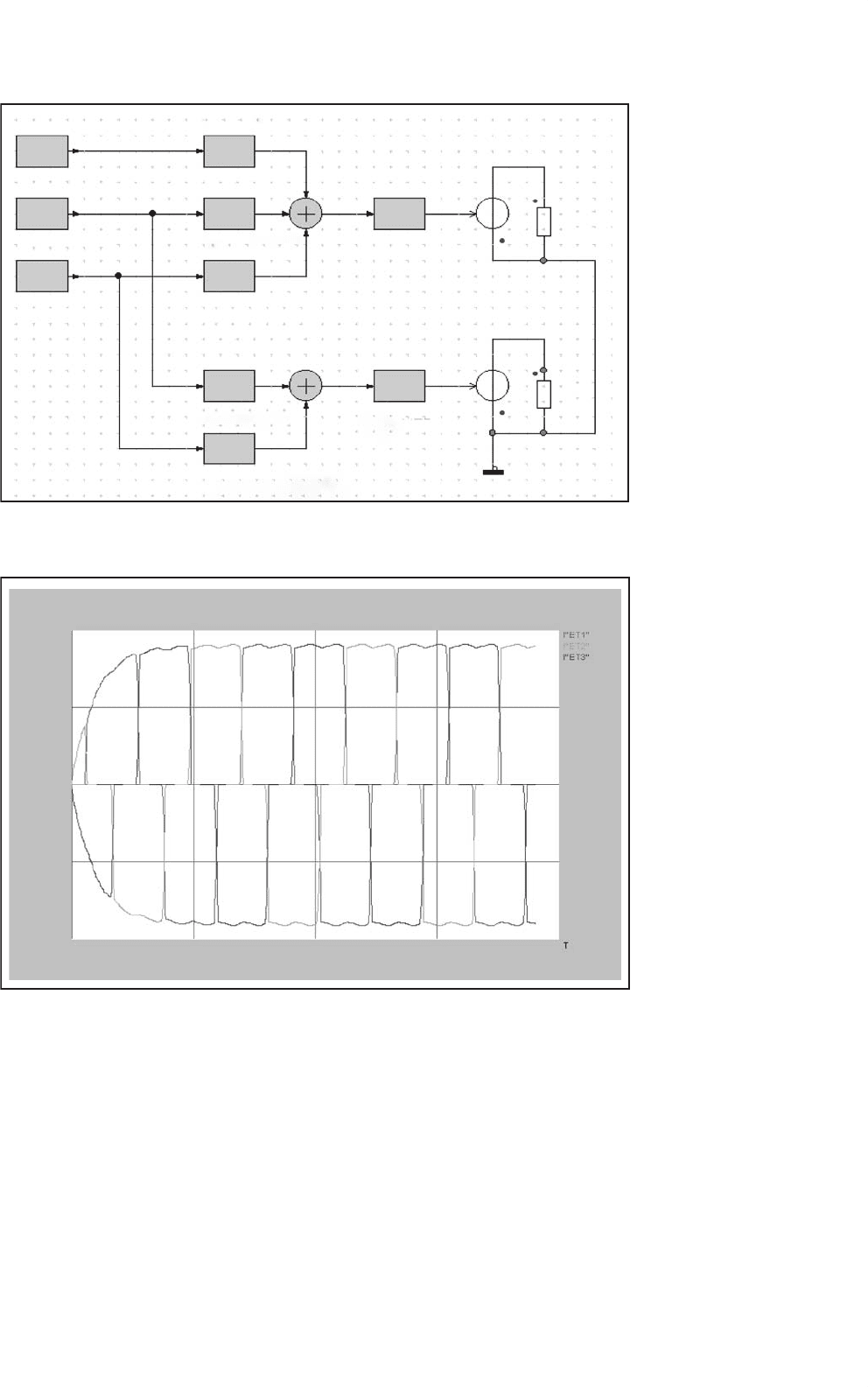
41.7 Simulations Using Simplorer
®
In the following, some examples of simulations with the eval-
uation version of Simplorer
[11], Release 4.1 are shown.
It should be acknowledged at this point that these exam-
ples have been created by Ali Ricardo Buendia, who obtained
M.S.E.E degree from Texas Tech University. The advantages
of Simplorer
are that it has a lot of models for power elec-
tronics devices and machines built-in, since it is specialized
for this type of simulation. Also, no numerical convergence
problems have been noticed thus far. Figure 41.23 shows the
schematic for a three-phase diode rectifier. The input is a
balanced three-phase source with a reactive source impedance.
An exponential characteristic, closely resembling real diodes,
has been chosen as a model for the diodes.
Figure 41.24 shows a circuit, which transforms the load
currents from a three-phase to a two-phase system. Here the
1142 M. Giesselmann
20V
10V
0V
50V
25V
0V
15V
SEL
>>
10V
0V
0s 0.4s 0.8s
Time
1.2s 2.0s1.6s
5V
750mV
500mV
250mV
0V
V(NoSen_Vec_ContrI1.I_sd)
V(Flux)
V(Torque) V(Motor1:Torque)
Torque & Torque Command
Mechanical Angular Velocity, 1V = 1rad/s
Flux Reference, 1V = 1Vs
Current Command IQ, 1V = 1A
Current Command ID, 1V = 1A
V(Motor1:0mech)
V(NoSen_Vec_ContrI1.I_sq)
FIGURE 41.22 Simulation results for sensorless vector control.
Sine_R
Sine_S
Sine_T
ET3
ET2
ET1
L2
L3
L4
–
–
–
+
+
+
EXP1
EXP
L1
R1
+
+
FIGURE 41.23 Simplorer
schematics for three-phase rectifier.
41 Computer Simulation of Power Electronics and Motor Drives 1143
EXT
EXT
EXT
Phase_C_I
Phase_B_I
Phase_A_I
GAIN_2
P
P
P
P
P
P
t
t
P
G1_SQRT_3
G1_MINUS_SQRT_3
B_1_OVER_3
A_1_OVER_3
R_Beta
R_Alpha
G1minus_one
G2minus_one
FIGURE 41.24 Three-phase to two-phase conversion for load currents.
2.18
1.09
–1.09
–2.18
0
0 13.1m 26.3m 39.4m 52.5m
FIGURE 41.25 Simplorer
plot of load currents for the three-phase rectifier.
D and Q components are called alpha and beta components
respectively. The results of the simulation are shown on the
same page that is used for the schematic diagrams shown by the
previous two figures. Figure 41.25 shows a plot of the line cur-
rents during the start-up of the rectifier, where the initial load
current is zero. The next graph shows a plot of the line currents
that have been transformed by the circuit shown in Fig. 41.26.
The components of the line currents are the variables of the
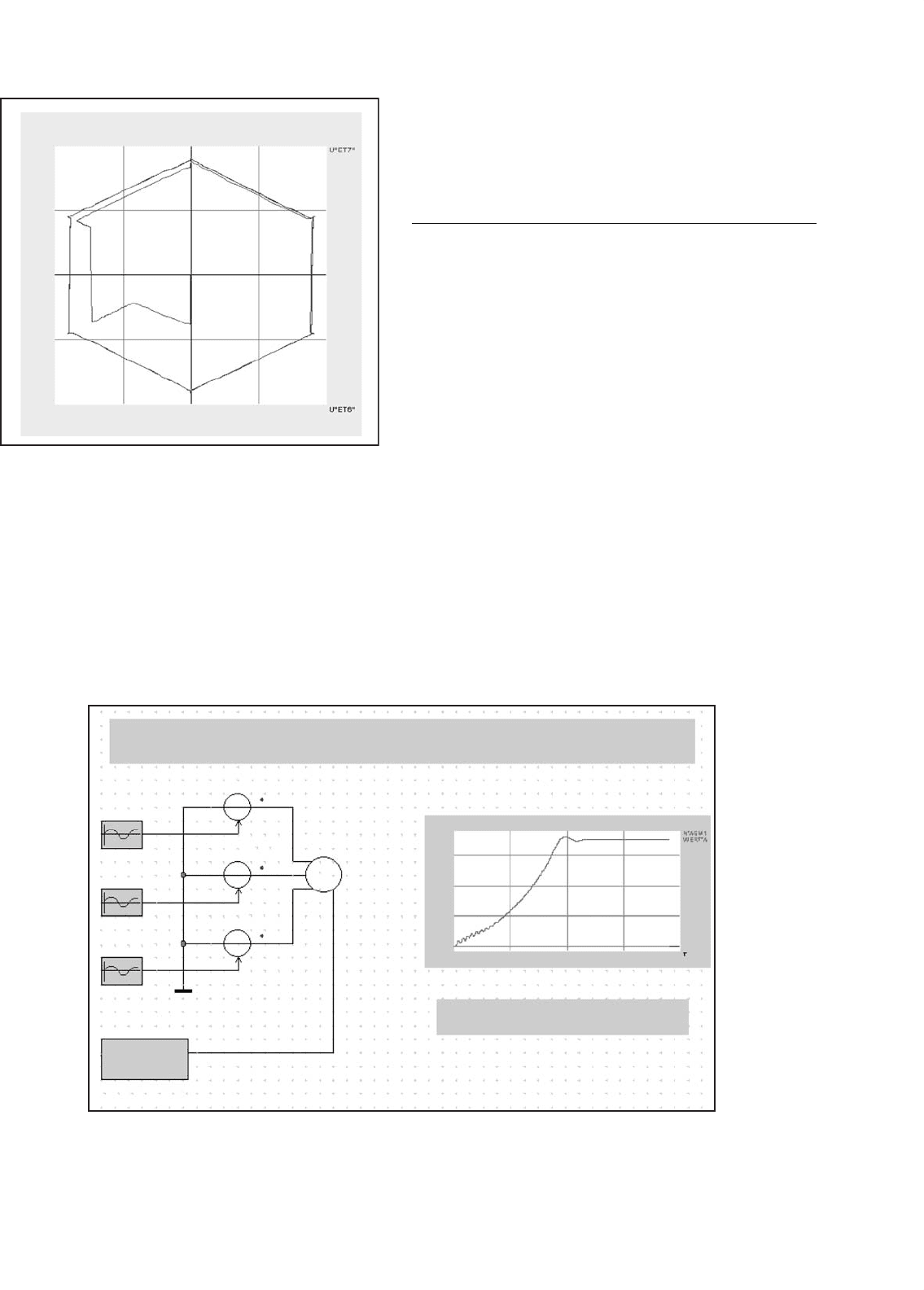
axes. The plot shows the typical hexagonal trace that can be
expected for this type of line-commutated rectifier (six step
operation). If the converted source voltages were plotted in
this fashion, a perfect circle would be the result.
The last two graphs demonstrate a Simplorer
simulation of
the start of an induction motor. As previously mentioned, the
1144 M. Giesselmann
2.51
–2.51
–2.18 2.180–1.09 1.09
1.26
–1.26
0
FIGURE 41.26 Plot of converted load currents for the three-phase
rectifier.
symbol and the model for the induction motor is built into the
code. Figure 41.27 shows the schematic with the source and the
induction motor as well as a graph that shows the rotational
speed as a function of time. The graph below shows plots of
the stator and rotor flux components, which are available from
~
Sine_R
Sine_S
Sine_T
ET1
ET2
ET3
ASM1
1.62k
1.27k
0.85k
0.42k
0 0.26 0.53 0.79 1.05
–0.081k
Rotational Speed
GMM_ASYM1
Parameters
Asynchron. machine
with Squirrel-cage
Rotor
Simulation of a squirrel cage Induction motor
TSR
M
3
ttt
FIGURE 41.27 Simplorer
schematics for induction motor start.
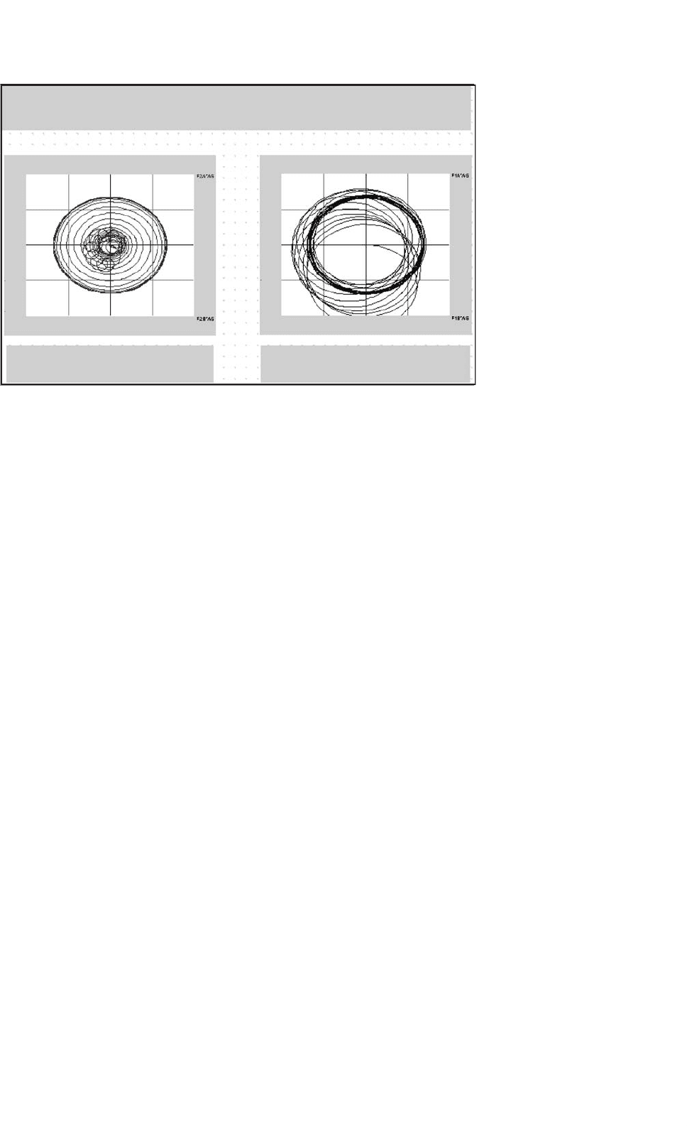
the machine model. Like the plot of the current components
for the rectifier, the flux components are the variables of the
axes in the graphs of Fig. 41.28.
41.8 Conclusions
In this chapter, the capabilities of PSpice
[12] and
Simplorer
[11] have been used to simulate a number of
projects from the power electronics, machines, and drives area.
The advantage of PSpice
is that it is based on the almost uni-
versal Spice simulation language, which can be seen as the
worldwide de facto standard. On the other hand, Simplorer
has the advantage of built-in machine models. If both pro-
grams are used, comparisons and mutual validations of models
can be performed. The reader should always validate any
model before it is used for critical engineering decisions. It
was pointed out in the introduction, that model validation
often means verification that the limitations of the model are
not exceeded.
In addition to the detailed examples, some general guide-
lines on the uses of simulation for analysis and design have
been developed. All tested programs yielded excellent results.
The simulation time for each project shown is typically less
than a minute on a typical (2005) PC. The author hopes, that
the reader has gotten an insight and appreciation of the power
of these modern simulation codes and some useful ideas and
inspirations for projects of his own.
41 Computer Simulation of Power Electronics and Motor Drives 1145
Simplorer's motor model provides the rotor and stator fluxes, rotational
speed and rotor currents as outputs for calculations or just a data display
1.50
–1.50
–1.50 1.500
0
0.75
–0.75
1.50
–1.50
0
0.75
–0.75
–0.75 0.75 –1.50 1.500–0.75 0.75
Rotor Flux in alpha–beta
coordinates
Stator Flux in alpha–beta
coordinates
FIGURE 41.28 Simplorer
plots of machine fluxes for induction motor start.
References
1. N. Mohan, T. Undeland, and W. Robbins, “Power Electronics, Con-
verters, Applications, and Design,” 2nd edition, John Wiley & Sons,
New York, 1995, ISBN: 0-471-58408-8.
2. A. M. Trzynadlowski, “The Field Orientation Principle in Control of
Induction Motors,” Kluwer Academic Publishers, Inc., Boston, MA
1994, ISBN: 0-7923-9420-8.
3. P. C. Krause, O. Wasynczuk, and S. D. Sudhoff, “Analysis of Electric
Machinery,” IEEE Press, Hoboken, NJ 1995, ISBN: 0-7803-1101-9.
4. M. G. Giesselmann, “Averaged and Cycle by Cycle Switching
Models for Buck, Boost, Buck-Boost and Cuk Converters with com-
mon Average Switch Model,” Proceedings of the 32nd Intersociety
Energy Conversion Engineering Conference, IECEC-97, Honolulu,
HI, July 27–Aug. 01, 1997.
5. M. Giesselmann, “A PSpice
Tutorial for Demonstrating
Digital Logic,” IEEE Transactions on Education, Nov. 1999,
http://coeweb.engr.unr.edu/eee/59/CDROM/Begin.htm.
6. D. W. Novotny and T. A. Lipo, “Vector Control and Dynamics
of AC Drives,” Oxford Science Publications, New York, NY 1996,
ISBN: 0-19-856439-2.
7. P. Vas, “Vector Control of AC Machines,” Oxford Science Publica-
tions, 1990 ISBN: 0-19-859370-8.
8. A. Von Jouanne, D. Rendusara, P. Enjeti, and W. Gray, “Filtering
Techniques to Minimize the Effect of Long Motor Leads on PWM
Inverter Fed AC Motor Drive Systems,” IEEE Transactions on
Industry Applications, July/Aug. 1996, pp. 919–926.
9. K. Hasse, “Zur Dynamik Drehzahlgeregelter Antriebe mit Strom-
richter gespeisten Asynchron-Kurzschlussl
´
’aufermachinen,” (On the
Dynamics of Adjustable Speed Drives with converter-fed Squirrel
Cage Induction Machines), Ph.D. Dissertation, Technical University
of Darmstadt, 1969.
10. ACI3_4: Sensor-less Direct Flux Vector Control of 3-phase ACI Motor,
Data Sheet, Texas Instruments Incorporated, 12500 TI Boulevard,
Dallas, TX 75243-4136, 800-336-5236.
11. Simplorer
, Technical Documentation, Ansoft Corporate Head-
quarters, 225 West Station Square Drive, Suite 200, Pittsburgh,
PA 15219, USA, (412) 261-3200, http://www.ansoft.com/products/
em/simplorer/.
12. PSpice
Documentation, 2655 Seely Avenue, San Jose, California
95134, USA, (408) 943-1234, http://www.cadence.com/.

42
Packaging and Smart
Power Systems
Douglas C. Hopkins, Ph.D.
Dir.—Electronic Power and Energy
Research Laboratory, University
at Buffalo, 332 Bonner Hall,
Buffalo, New York, USA
42.1 Introduction ........................................................................................ 1147
42.2 Background ......................................................................................... 1148
42.3 Functional Integration ........................................................................... 1148
42.3.1 Steps to Partitioning
42.4 Assessing Partitioning Technologies ......................................................... 1149
42.4.1 Levels of Packaging • 42.4.2 Technologies • 42.4.3 Semiconductor Power
Integrated Circuits
42.5 Cost-driven Partitioning [5] ................................................................... 1153
42.6 Technology-driven Partitioning ............................................................... 1154
42.7 Example 2.2 kW Motor Drive Design ....................................................... 1155
42.7.1 User Requirements (Constraints) • 42.7.2 Component Characterization Map
• 42.7.3 Component Grouping • 42.7.4 Strategic Partitioning with Constraints
• 42.7.5 Optimization within Partitions
42.8 High Temperature (HT) Packaging [6] ..................................................... 1157
42.8.1 HT Materials Selection • 42.8.2 Module Construction
Further Reading ................................................................................... 1158
42.1 Introduction
A continual endeavor in power electronics is to increase power
density. This is achieved by shrinking component size, moving
components closer, and reducing component count. During
the last two decades, circuit frequencies increased sharply to
shrink component dimensions. Improved thermal manage-
ment and physical packaging materials brought components
closer, and finally, increased integration of functions at the
semiconductor and package levels reduced component count.
This has been marked in the microelectronics world by “system
on chip” (SOC), “system in package” (SIP), and “system on
package” (SOP) with subsystems including “stacked die” and
“multichip modules” (MCMs), all addressing higher densities
and all applicable to lower power, power electronic systems.
The approach of “functional integration” has been ongoing
for decades. Until the 1980s, nearly all such integration was
done at the packaging level melding control and power
processing. The term “smart power” (within the context of
power electronic conditioning) applied in the 1960s–1970s
to the integration of computers and microprocessors into
large rectifier and converter cabinets. With the advent of
high-voltage-silicon integrated circuits, more functionality was
brought directly to the power semiconductors, and in the
1980s–1990s the term applied mostly to smart power semi-
conductors. In the late 1990s, there was a move back to
hybrid integration following the trend to SOP. During the
1980s–1990s “smart power” also became associated with digital
control of higher power systems, such as motor drives and
uninterruptible power supply (UPS) systems and became
commercially associated with power management circuits. The
first decade of the twenty-first century has ushered in “digi-
tal power” for direct control of high-frequency inner control
loops in power supplies. Smart power is now more generically
used since the cost of digital controllers, such as microcon-
trollers and programmable ICs (pics), are low cost and easily
used throughout the power electronic systems.
From a designer’s perspective, “functional integration”
exists in a packaging continuum with “smart power” as a sub-
set dependent on the definition in vogue. To take advantage
of “functional integration” the designer, in reverse thinking,
partitions or modularizes circuits, and functions to achieve
1147
Copyright © 2001 by Academic Press

1148 D. C. Hopkins
the most cost-effective approach that meets a set of required
performance specifications. This chapter provides background
information, framework, and procedures to produce partition-
ing and functional integration.
42.2 Background
Circuits are typically designed based upon a pre-determined
set of packaging technologies ranging from silicon integra-
tion of sub-circuit functions to multiple boards in a rack.
Partitioning a circuit for packaging in one technology, such
as all silicon, is straightforward. Partitioning for multiple
technologies is much more difficult since higher performing
technologies duplicate the aspects of lower technologies. The
duplication geometrically increases parameter trade-offs and
complicates design. A study on the status on power electronics
packaging (STATPEP) [1] identifies metrics to evaluate the
relative technical merits of the technologies.
To optimize the use of multiple technologies in functional
integration, a structured method should be used. A full-cost
model for various technologies is used as a basis to produce
a comparative cost diagram. The diagram allows intermixing
of high and low performance technologies based on surface
density, which is interpreted as circuit area and, hence a par-
tition. An example is given in Section 42.7 to demonstrate the
method using a 2.2 kW motor-drive module product.
The method is also applied to product modularization, i.e.
system partitioning where a specific function is used across
several products. A module can represent functional integra-
tion within a packaging technology or use multiple packaging
technologies to create integrated power modules (IPMs) or
power electronic building blocks (PEBBs). The importance of
modularization is to increase the product volume to lower
cost. The cost model includes variations based on volume.
This partitioning approach matches user requirements to
“Levels of Packaging” as defined in the “Framework for Power
Electronics Packaging”[2] and provides optimum integration
of packaging levels for a product. The framework also identifies
critical technical issues that need to be considered in evaluat-
ing technical performance. This partitioning approach looks at
electrical, magnetic, thermal, and mechanical issues (multiple
energy forms).
42.3 Functional Integration
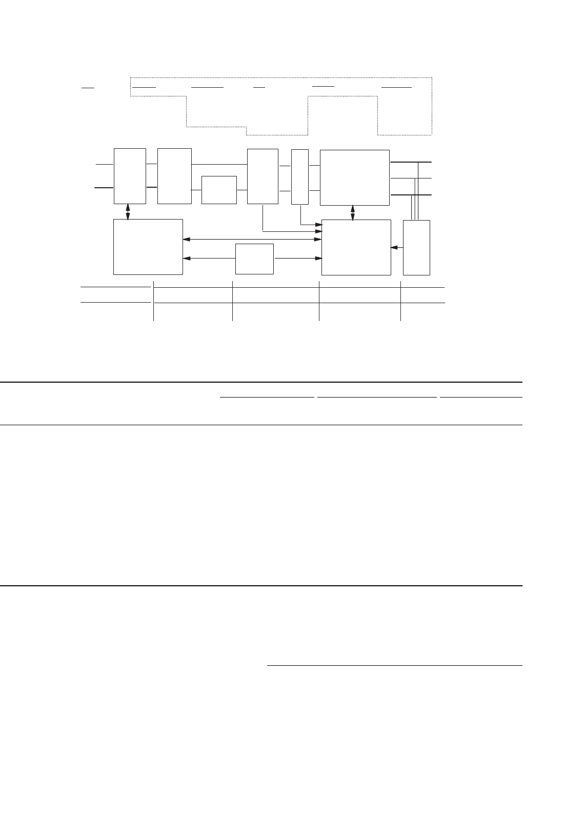
Figure 42.1 shows a 2.2 kW ac motor drive. Functional inte-
gration requires that the system should be partitioned both
electrically and physically. The systems integrator is usually
an electrical designer and the first partitioning is usually elec-
trical. The electrical partitions and distributed power losses
are also shown in the figure. The physical partitioning, or
packaging, involves different components with different func-
tions ranging from fine-line control to high-current, high-loss
power processing. Several partitions can be pursued. The line-
communications and motor-control blocks can use a signal-
level packaging approach, such as all-silicon application-
specific integrated circuit (ASIC), or discrete components on
an epoxy-glass flame resistant 4 (FR-4) or insulated-metal sub-
strates (IMS). If the power supply and control blocks are to
be combined, a surface mount technology (SMT) approach
cannot accommodate bulky storage components in the power
supply. Hence, a through-hole approach is considered for
part or both blocks. Regardless, such trade-offs can be nearly
endless.
A structured method needs to be used to establish essential
requirements and guide circuit and system partitioning. The
method described here is based on characterizing and grouping
the components, evaluating the cost and technical constraints,
and then, matching packaging technologies to the groupings.
All this is set against a set of comprehensive user requirements.
42.3.1 Steps to Partitioning
A first step to partitioning is creation of a comprehensive cate-
gorized list of electrical, mechanical, and thermal, technical
user requirements. The second step is creation of a sim-
ple component characterization map that identifies dominant
attributes of the components. The block diagram of a 2.2 kW
motor drive is shown in Fig. 42.1 and a partial characterization
map is given in Table 42.1. The map is divided into metrics by
energy form to categorize and record extreme operating values
for each component. Not all blocks need to be completed or
components included, only those that most impact the tech-
nology selection. For example, any 5 V, <0.1 W resistor in the
control circuit need not be listed since it is accommodated
by nearly all technologies (e.g. as 0806, SMT, plated through
holes (PTH), thick film, etc.). For each of the remaining com-
ponents, all the mechanical package formats should be listed
under the delivery form.
The third step is to strategically group components by deliv-
ery form taking into consideration limits on electrical and
thermal operating points. This first-cut grouping brings a high
level of packaging integration to the system and is a critical
step. Similar components from all parts of the circuit become
associated.
The fourth step uses the user requirements as constraints
along with the engineering experience to re-associate compo-
nents into different groupings. Not all components are easily
regrouped. The unassociated components become dominant
factors during technology selection. As an example, the high-
voltage components of a bootstrap gate-drive supply can be
associated with the gate-drive circuit board or the high-voltage
power inverter components. Interestingly, most unassociated
components reside at the interfaces between functional blocks
(as shown in Fig. 42.1).
42 Packaging and Smart Power Systems 1149
PFC
2 die 23W
1 shunt 2W
1IC
1 diodes
8 SMD
12 Resistors
1 coil 15W
INVERTER
12 dies 102W
1 shunt 2,5W
1 HVIC
13 diodes
13 SMD
23 Resistors
DC link
1 Voltage divider
2
Capacitors 7W
VDE/inrush
1 dies 15W
1 shunt 2W
1 IC
4SMD
8 Resistors
1VDR
Rectifier
5 dies 20W
EMC
1 coil 10W
10 X,Y,pulse
-caps
3VDR
1 Resistor
Code
Leaded
SMD/die/TF
Line communication
1 coil 5W
1IC ½W
27 SMD
Motor control/uP
3 IC
12 SMD
Power suply
1 Transformer ½W
4 Capacitors
1IC 1W
9SMD
BEMF
2 IC
3 SMD
36 Resistors
L1
L2
Rectifier
DC
link
Inverter
Motor control
uP
Power
suply
VDE
inrush
BEMF
Line
communication
A
B
C
PFC
EMC
Leaded (outside
the dotted box)
SMD/die/TF (inside
the dotted box)
FIGURE 42.1 Block diagram of a 2.2 kW motor-drive module.
TABLE 42.1 Component characterization map (partial listing)
Functional block Function Component Quantity Mechanical Electrical Thermal
Delivery form Size Voltage Current Constraint Loss Max temp
V A/comp W/comp
◦
C
Rectifier Bridge Diode 4 die 3.5 ×2.5 600 11 rms 5 125
Clamp Diode 4 die 3.5 ×2.5 600 <1 125
Inrush/ VDE Switch IGBT 1 die 6 ×4.3 1,200 11 rms 15 125
Current sense Shunt 1 TF 11 rms 2
Controller IC 1 die <18 <1 125
Support C R 4 8 SMD TF 0603
Transient clamp VDR 3 leaded φ21 ×5 300 ac Low L
PFC Switch MOS 1 die 7.5×7.5 500 26 peak 16 125
Freewheel Diode 1 die 3×4 500 7 125
Current sense Shunt 1 TF 11 rms 2
Controller IC 1 die 10 m <1 125
Support C R 8 12 SMD TF 0603 <70 V
Choke L 1 leaded 500 11 rms 15 130
DC-link DC-cap E-lytics 2 leaded φ26×50 500 1.25 rms 3.5 75
Voltage sense R 2 TF
The fifth step is to map the groupings of components to the
packaging technologies. This was partially performed in the
previous step as engineering judgment guided the regrouping.
Refinement of the selection comes when the unassociated com-
ponents are incorporated. Steps four and five become iterative
to provide optimum partition(s).
42.4 Assessing Partitioning Technologies
To better understand the correlation between electrical and
physical circuits (partitioning and packaging), consider the
morphology of a generic circuit. A circuit has three parti-
tions: components, topologies, and controls. Components are