Power electronic handbook
Подождите немного. Документ загружается.

41 Computer Simulation of Power Electronics and Motor Drives 1129
+
+
+
+
−
+
+
Load
Mechanical Model:
Electrical Model:
GAIN = 1
GAIN = 1
Hsq
Rs_q
LsI_q
I_sq
I_sd
I_rd
{1.5*@LM*@POLES/2}
I_sq
I_sd
I_rd
I_rq
E_Tsum
IN1+
IN1− OUT+
IN2+ OUT−
IN2−
Hsd
D
Q
Rs_d
{@R_STAT}
LsI_d
{@R_STAT}
{@LSL}
ESUM
{@LSL}
{@LRL}
LrI_d
Rr_d
Rr_q
Lmag_d
Lmag_q
Lrl_q
l_sd
l_sq
l_rd
l_rq
l_rq
{@OMEGA_INIT}
{1/@J_MOT}
Torque
OMEGA_mech
{@LM}
{@LRL}
{@R_ROT}
{@R_ROT}
{@LM}
GAIN = 1
GAIN = 1
GAIN = 1
Hrd
Hrq
H_Load
Omech
Om_e
Om_e
Om_e
Torque
{@POLES/2}
Rotational Voltages:
(V(%IN1)
*@LM
+V(%IN2)
*@LR)
(–1)*(V(%IN1)
*@LM
+V(%IN2)
*@LR)
−
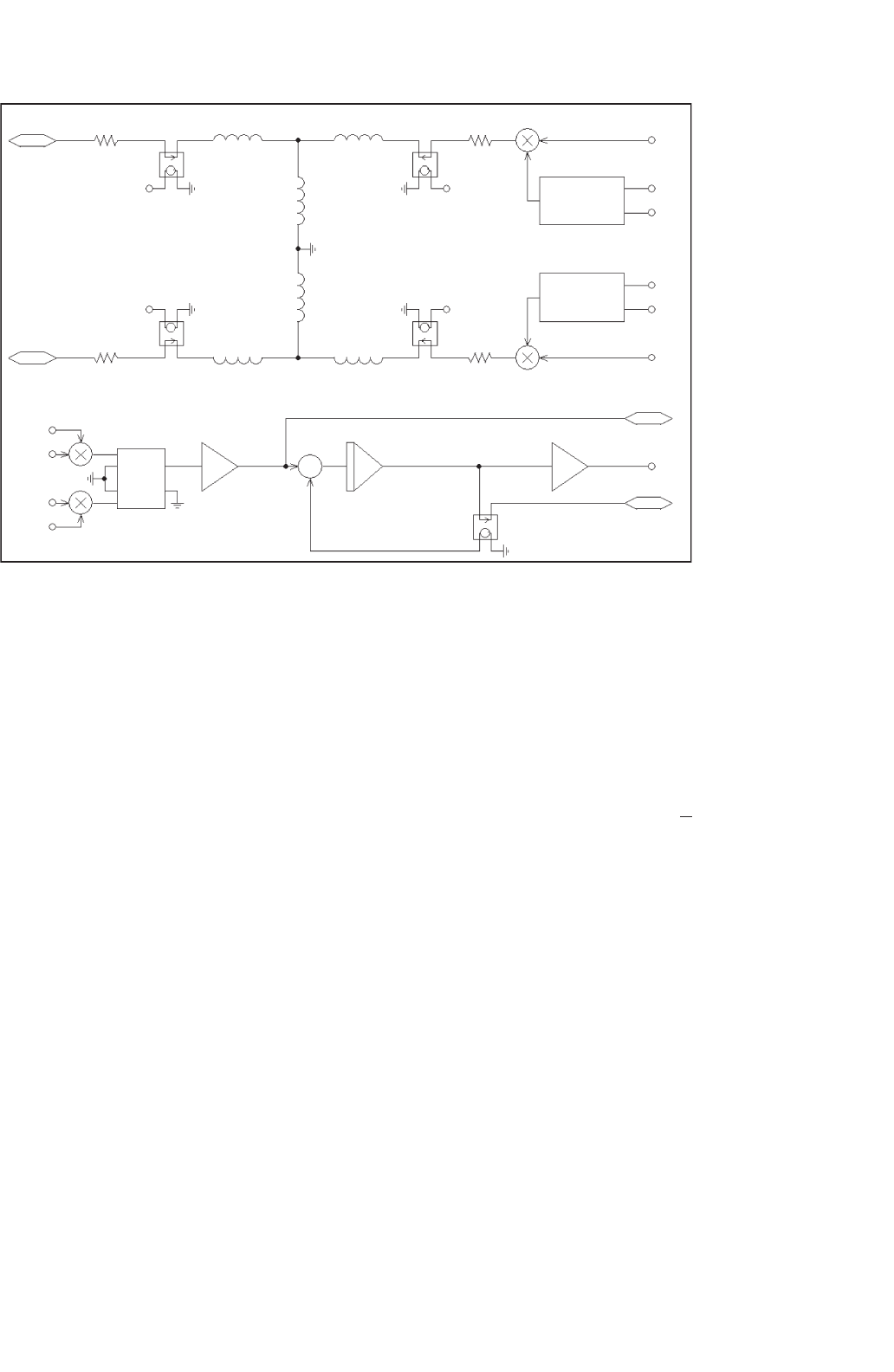
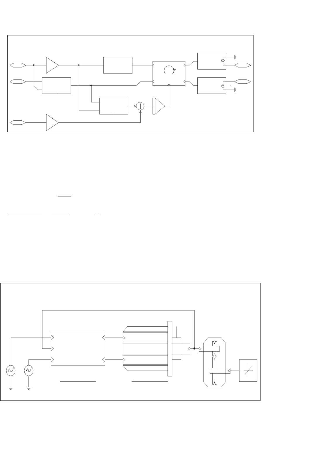
FIGURE 41.9 Subcircuit for induction motor model.
in this way is that several symbols can call one set of subcircuits
with different parameters.
Right-clicking on the motor symbol and selecting “Descend
Hierarchy” reveals the associated subcircuit that implements
its function. This subcircuit is shown in Fig. 41.9. The upper
portion of this subcircuit represents the electrical model. The
task of the electrical model is to calculate the stator and rotor
currents, with the stator voltages and the mechanical speed
of the machine being input parameters. However, it is also
possible without any changes, to feed stator currents (with
controlled current sources) into the D and Q inputs and have
the model to calculate the appropriate stator voltages. This
option is useful for vector control applications, which are
discussed later.
The equation system for the electrical model of a two-phase
induction machine is given by Eq. (41.3). The theory for this
equation system is derived in [2, 3, 6, 7]. The equation sys-
tem and the model are formulated for the stationary reference
frame. This reference frame assumes that the frame of the
machine is stationary (which is hopefully the case in a real
machine!) and the voltages and currents of the rotor are equiv-
alent AC values with stator frequency. From machine theory
we know that the actual rotor currents have slip frequency.
Another reference frame is the synchronous (also called exci-
tation) reference frame. In this reference frame, the stator of
a fictitious machine is assumed to rotate with synchronous
speed. The advantage of this reference frame is that the input
frequency is zero (DC), which makes it easy to explain the
principle of vector control by extending the theory of DC
machines to AC machines.
V
d
V
q
0
0
=
R
stat
+pL
s
0 pL
m
0
0 R
stat
+pL
s
0 pL
m
pL
m
ω
e
L
m
R
rot
+pL
r
ω
e
L
r
−ω
e
L
m
pL
m
−ω
e
L
r
R
rot
+pL
r
I
sd
I
sq
I
rd
I
rq
L
s
=L
m
+L
s1
L
r
=L
m
+L
r1
p =
d
dt
(41.3)
In typical implementations of vector control using digital
signal processors (DSPs), the synchronous reference frame is
used internally to calculate the reference values for the currents
in the D and Q axis. These values are then transformed to the
stationary reference frame in an additional step. Sometimes
still other reference frames are used and it is possible to gen-
erate a universal electrical model with a reference frame speed
input. This model could then be used for any reference frame.
The electrical model in Fig. 41.9 implements the equation
system shown in Eq. (41.3). The circuit closely resembles the
well-known T-equivalent circuit for the steady-state analysis of
induction machines. Two instances of the T-equivalent circuit
are necessary to implement the two-phase (D, Q) model. The
two instances of the circuit are almost mirror images of each
other (and actually drawn that way) except for some differ-
ences in the circuit elements that calculate the voltages, which
are generated due to the rotation of the rotor. The bottom of
1130 M. Giesselmann
Fig. 41.9 represents the mechanical model. This circuitry cal-
culates the internally generated electro-magnetic torque, using
the rotor and stator currents as input values. The equation for
the internal electromagnetic torque of the induction machine
is given by Eq. (41.4) [3, 6, 7]. The factor 3/2 accounts for the
fact that the real motor is a three-phase machine. Using the
generated torque, the load torque, and the moment of inertia,
the angular acceleration can be calculated. Integration of the
angular acceleration yields the rotor speed, which is used in
the electrical model. To avoid clutter and to improve readabil-
ity, connection bubbles are used to connect the various parts
of the model together.
T =
3
2
P
2
L
m
I
sq
I
rd
−I
sd
I
rq
(41.4)
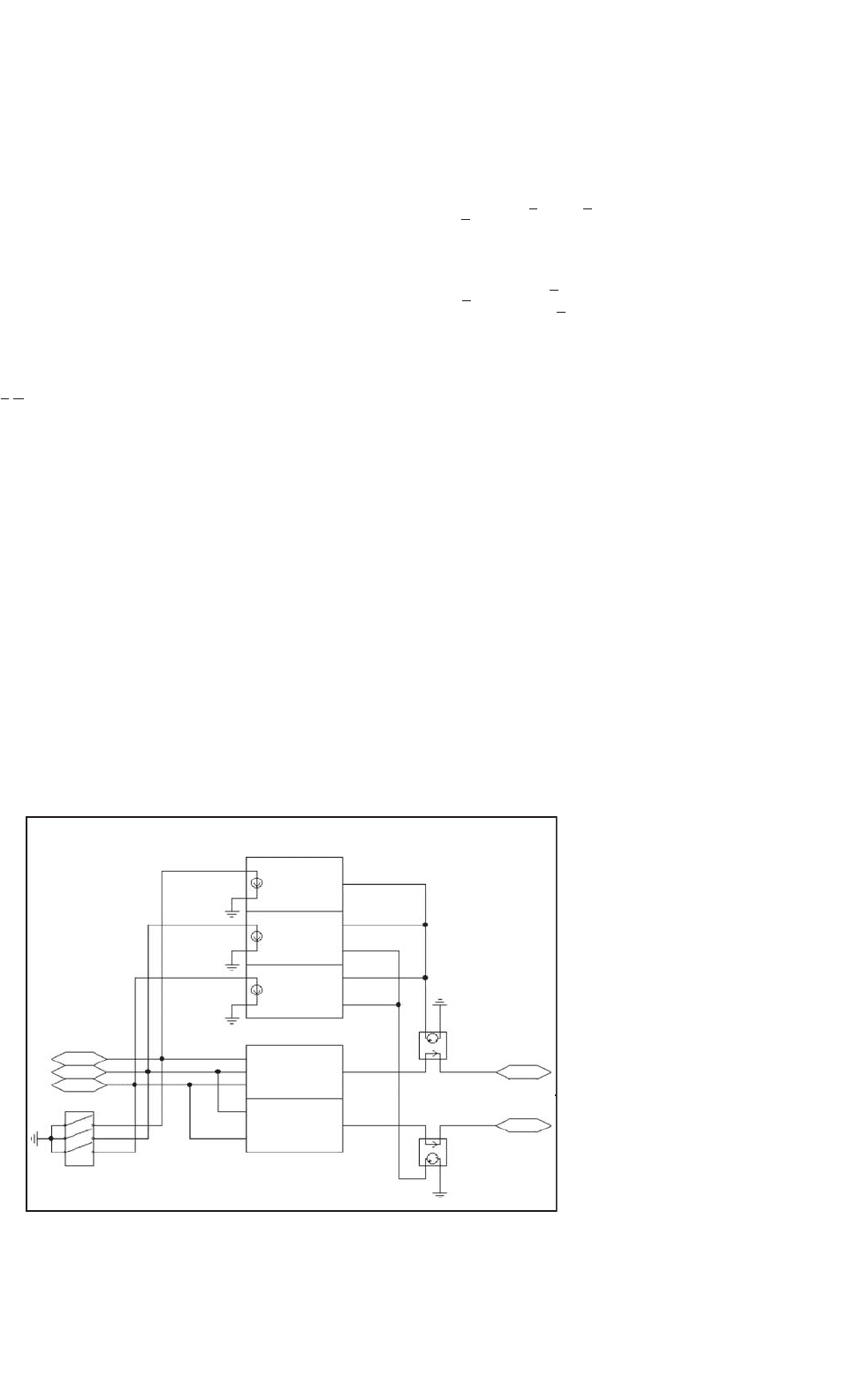
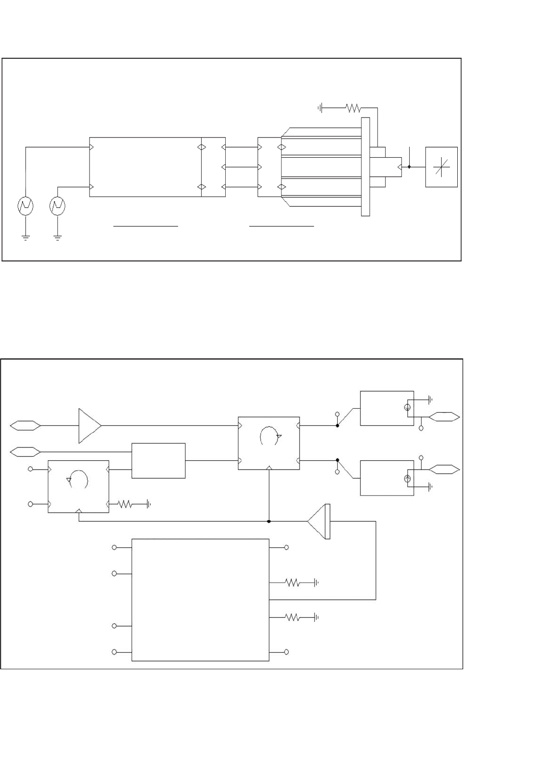
Since typical induction machines are three-phase machines,
it is often desirable to have a machine model with a three-
phase input. Therefore, a bidirectional two-phase to three-
phase converter module, which can be attached to the motor,
has been developed. A subcircuit for this module is shown in
Fig. 41.10. This circuit is truly bidirectional, meaning that the
circuit can be fed with voltage or current sources from either
side. The equation system for this voltage and current invariant
transformation is given by Eq. (41.5). This transformation is
sometimes called “Clark” or “ABC–DQ” transformation. Note
that V
0
denotes a zero-sequence voltage, which is assumed to
be zero. This voltage would only have non-zero values for
unbalanced conditions. An interesting detail of the subcircuit
is the three-phase switch on the input. This switch is necessary
to ensure a stable initialization of the simulator in case the
machine is fed with a controlled current source. The switch
Simulation Startup Support
for Current Source Drive
GAIN = 1
RON = 500
ROFF = 50k
TOFF = 1ms
A
B
C
V(%IN)
−V(%IN1)/2
+sqrt(3)
∗
V(%IN2)/2
−V(%IN1)/2
−sqrt(3)
∗
V(%IN2)/2
(V(%IN1)
−V(%IN2)/2
−V(%IN3)/2
*2/3
(V(%IN1)
-(V(%IN2))
/SQRT(3)
ABC <−> DQ Transformation:
GAIN = 1
D
Q
H_d
H_q
FIGURE 41.10 Subcircuit for the ABC–DQ transformation module.
provides an initial shunt resistor from the three-phase input to
ground. Soon after the simulation has started, the switch opens
and leaves only a negligible shunt conductance to ground.
V
d
V
q
V
o
=
1
3
2 −1 −1
0
√
3 −
√
3
11 1
V
a
V
b
V
c
V
a
V
b
V
c
=
1
2
202
−1
√
32
−1 −
√
32
V
d
V
q
V
o
(41.5)
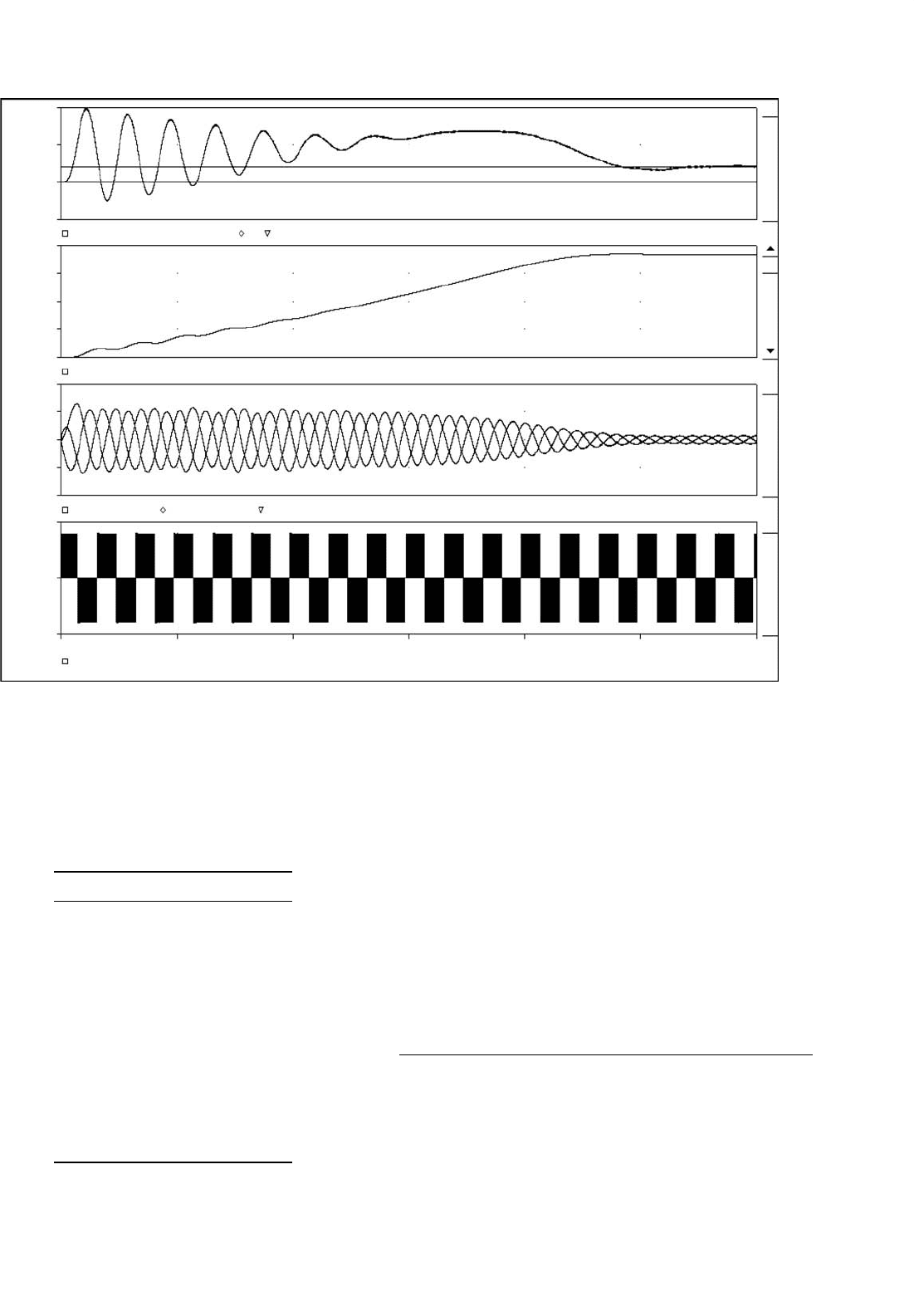
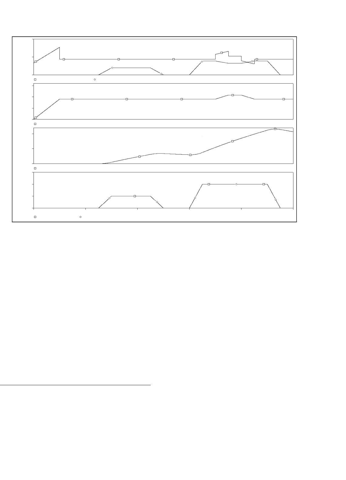
Figure 41.11 shows the result for the start-up of the induc-
tion motor for the circuit of Fig. 41.8. The motor is a half
(Attention LE(½)) hp, 208 V, 4-pole machine. The detailed
parameters are shown in Table 41.1. The PWM generation
was identical to the example shown in Fig. 41.4, except that
the switching frequency was 4 kHz and 21.1% of the third
harmonic has been added to each of the reference sinusoids
in order to increase the linear modulation range. The result-
ing reference waveform was then multiplied with 1.14, which
represented the maximum voltage for linear modulation. The
top trace in Fig. 41.11 shows the developed electromagnetic
torque, the level for the rated steady-state torque (4 Nm as
commanded by the load in Fig. 41.8) and the zero level. This
graph shows the typical oscillatory torque production of the
induction machine for an uncontrolled line start. The scale
for this graph is 1 V = 1 Nm. The graph below shows the
mechanical angular velocity with a scale of 1 V = 1 rad/s.
Below the graph for the rotor speed, all three input currents
are shown. It is evident, that the current traces are almost
perfect sinusoids, despite the fact that the input voltage is the
41 Computer Simulation of Power Electronics and Motor Drives 1131
20
10
0
−10
200V
150V
100V
50V
0V
40A
20A
0A
−20A
−40A
500V
−5000
0V
SEL>>
Torque, 1V = 1Nm
V(Motor1:Torque_Monitor)
V(Motor1:Omech)
I(R_sense_a) I(R_sense_b) I(R_sense_c)
Rotor Speed, 1V = 1rad/s
Stator Currents
40
0s
50ms
100ms 150ms
Time
200ms 250ms 300ms
V(A,B)
FIGURE 41.11 Induction motor start-up with three-phase inverter circuit.
TABLE 41.1 List of all attributes used
for the half (Attention LE:
(
1/2
)
)hp, 208 V,
four-pole induction motor in Fig. 41.8
Attributes:
PART = Induction_Servo
MODEL = Ind_Motor
TEMPLATE =
J_mot = 0.01
Omega_init = 0.0
Ls = (@Lm + @Lsl)
Lr = (@Lm + @Lrl)
Poles = 4
Tau_r = (@Lr/@R_Rot)
REFDES = Motor?
Lsl = 14.96mH
Lrl = 8.79mH
R_Stat = 3.60
R_Rot = 1.90
Lm = 424.41mH
PWM waveform shown in the bottom graph. Also, the trace
for the torque shows no discernable high frequency ripple.
The reason is, of course, that the motor windings are induc-
tive, and represent a low-pass filter for the applied voltages.
Nevertheless, recent research suggests that filtering the out-
put voltage of the inverter is advantageous anyway, because
it significantly reduces the voltage stress on the windings and
suppresses displacement currents through the bearings [8].
41.5 Simulations of AC Induction
Machines Using Field Oriented
(Vector) Control
The following examples will demonstrate the use of PSpice
for simulations of AC induction machines using field oriented
control (FOC). Again, it is assumed that the reader is famil-
iar with the basics of induction machine theory. Often times,
FOC is also called vector control, and both expressions can

1132 M. Giesselmann
be used interchangeably. The FOC was proposed in the 1960s
by Hasse and Blaschke, working at the Technical University of
Darmstadt [9]. The basic idea of FOC is to inject currents into
the stator of an induction machine such that the magnetic
flux level and the production of electromagnetic torque can
be independently controlled and the dynamics of the machine
resembles that of a separately excited DC machine (without
armature reaction; no cross coupling). The previously dis-
cussed two-phase model for the induction machine is very
helpful for studies of vector control and shall be used in
all examples. If a two-phase induction motor model for the
synchronous (or excitation) reference frame is used, the simi-
larities between the control of a separately excited DC machine
and vector control of an AC induction machine would be most
evident. In this case, the D input would correspond to the field
excitation input of the DC machine and both inputs would
be fed with DC current. Assuming unsaturated machines, the
current into the D input of the induction machine or the
field current in the DC machine would control the flux level.
The Q input of the induction machine would correspond to
the armature winding input of the DC machine and again
both inputs would receive DC current. These currents would
directly control the production of electromagnetic torque with
a linear relation (constant k
T
) between the current level and
the torque level. Furthermore, the Q component of the current
would not change the flux level established by the D compo-
nent (no cross coupling). To make such a simulation work,
it would finally be necessary to calculate the slip value that
corresponds to the commanded torque and supply this DC
value to the D, Q (synchronous reference frame) machine
model.
Of course this is very interesting from an academic stand-
point and the author uses this example in a semester long
lecture on FOC. However, it should again be noted, that a
machine represented by a model with a synchronous reference
frame would have a stator, which rotates with synchronous
speed. Of course this is not realistic and therefore it is more
interesting to generate a simulation example that uses the
previously discussed motor with a model for the stationary
reference frame. This motor must be supplied with AC volt-
ages and currents with a frequency determined mostly by the
rotor speed to a small extent by the commanded torque. We
still supply DC values representing the commanded flux and
torque but we transform these DC values to appropriate AC
values. In the following example, we will assume that we can
measure the actual rotor speed with a sensor. This can, in
effect, be easily accomplished and many types of sensors are
available on the market. If we add the slip speed, that we
determine mathematically from the torque command, to the
measured rotor speed, we obtain the synchronous speed for
the given operating point. With this synchronous speed we can
transform the DC flux and torque command values from the
synchronous reference frame to the stationary reference frame.
We accomplish this by using a rotational transformation
according to the matrix equations in Eq. (41.6). This rotational
transformation is also called “Park” transformation.
V
Dout
V
Qout
=
cos
(
ρ
)
−sin
(
ρ
)
sin
(
ρ
)
cos
(
ρ
)
V
Din
V
Qout
V
Dout
V
Qout
=
cos
(
ρ
)
sin
(
ρ
)
−sin
(
ρ
)
cos
(
ρ
)
V
Din
V
Qout
(41.6)
cos
(
ρ
)
−sin
(
ρ
)
sin
(
ρ
)
cos
(
ρ
)
cos
(
ρ
)
sin
(
ρ
)
−sin
(
ρ
)
cos
(
ρ
)
=
10
01
As shown in Eq. (41.6), the transformation is bidirectional
and the product of the transformation matrices yields the
unity matrix. For the following discussion we shall define the
transformation, which produces AC values from DC inputs
as a positive vector transformation and the reverse operation
consequently a negative vector transformation. The matrix
equation for the positive vector transformation is shown on
the left side of Eq. (41.6). The negative transformation is very
useful to extract DC values from AC voltages and currents
for diagnostic and feedback control purposes. We will also
make use of it for sensorless vector control, which is discussed
below. Both rotational transformations use the angle, ρ,inthe
equations. This angle can be interpreted as the momentary
rotational displacement angle between two Cartesian coordi-
nate systems; one containing the input values and the other,
the output values. This angle is obtained by integration of the
angular velocity with which the coordinate systems are rotating
(typically the synchronous speed).
In summary, we replaced a theoretical motor model using
a synchronous reference frame by a reference frame transfor-
mation of the supply voltages and currents. In fact, modern
DSPs like the TMS320C2000™ Digital Signal Controller series
from Texas Instruments are capable to perform both the
Clark and the Park transformation in both directions at very
high speeds [10]. These DSPs are well supported with proven
reference designs, including free software examples.
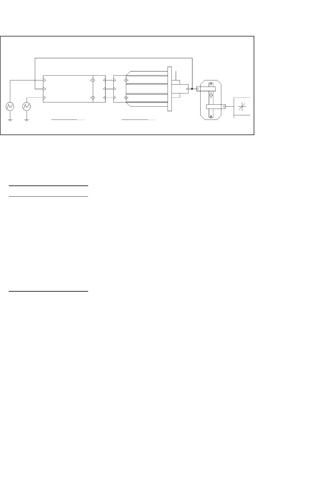
Figure 41.12 shows the top level of a simulation example that
implements vector control for an induction machine with a
stationary reference frame model. In fact, the motor model and
the associated subcircuits are identical to the ones used for the
circuit shown in Fig. 41.8. However, a more powerful motor is
used here, specifically a 3 hp, 4-pole 208 V motor with circuit
parameters shown in Table 41.2. As discussed above, the actual
speed of the rotor is used as an input signal for the control unit.
This scheme is known as indirect vector control and repre-
sents one of the most often used arrangements. The symbol
for the controller has the same parameters as the motor. This
is necessary to achieve correct field orientation. In real sys-
tems, the controller also must know or somehow determine
the machine parameters. The machine parameters could have
also been established globally using “PARAM” symbols, but
if the parameters for the controller can be set separately as it
is the case here, the influence of parameter mismatch on the
41 Computer Simulation of Power Electronics and Motor Drives 1133
24.5
PARAMETERS:PARAMETERS:
Indirect Vector Control of an Induction Motor:
Omega_mech
Vector Controller
Vector_Control1
Motor1
Torque
Torque
Omech
Omech
D
D
DD
QQC C
BB
AA
QQ
Torque
V_TorqueV_Flux
Flux
Flux
Gear1
RATIO = 0.5
880 RPM
Nm @
Lin_Load1
Induction_Servo
V_LL = 208
V_PH_PK = {Sqrt(2)*V_LL/sqrt(3)}
PSI_N = {V_ph_pk/Omega_n}
FREQ_N = 60
OMEGA_N={2*PI*Freq_n}
PI = 3.14159265
+
−
+
−
FIGURE 41.12 Top level circuit for indirect vector control of induction motors.
TABLE 41.2 List of all attributes for
the induction motor symbol for vector
control
Attributes:
PART = Induction_Servo
MODEL = Ind_Motor
TEMPLATE =
J_mot = 0.1
Omega_init = 0.0
Ls = (@Lm + @Lsl)
Lr = (@Lm + @Lrl)
Poles = 4
Tau_r = (@Lr/@R_Rot)
REFDES = Motor?
Lsl = 2.18mH
Lrl = 2.89mH
R_Stat = 0.48
R_Rot = 0.358
Lm = 51.25mH
performance of the control can be easily studied. An example
of this is given in Fig. 41.12.
Figure 41.12 also shows a symbol for a mechanical gear,
which is attached to the output of the induction motor. Let
us recall that the voltage on the mechanical output terminal
represents the angular velocity and the current represents the
torque. We also know that the product of the angular velocity
and the torque is the mechanical power. Therefore it is easily
understood that the electrical representation of an ideal gear
is an ideal transformer. The ideal transformer changes speed
(voltage) and torque (current) just like an ideal gear. Also
there are no power losses in an ideal transformer as well as in
an ideal gear.
In this fashion, many more mechanical properties and
devices can be modeled. For example, a mechanical flywheel is
simply represented by a capacitor to ground. Due to the scaling
factors for the angular velocity and the torque, a flywheel with
J =1 kgm
2
would be a capacitor with C = 1 F. The compliance
of a drive-shaft (elastic twisting by the applied torque) can be
modeled by a series inductor. By including both capacitors and
inductors, effects like mechanical resonance can be included
in a model.
Figure 41.13 shows the subcircuit for the vector control
unit. The central part is a vector rotator for positive direction.
This element transforms the DC reference values for the flux
(D-axis) and the torque (Q-axis) to the stationary reference
frame. The input angle for the vector rotator is the inte-
gral of the synchronous angular velocity. The signal called
“Omega_o” is the measured rotor speed.
This speed is multiplied with the number of pole-pairs
(poles/2) to obtain the electrical angular velocity. Then the
slip value (see Eq. (41.7) for slip frequency calculation for vec-
tor control) appropriate to the torque command is added and
the resulting signal is routed through an integrator to generate
the input angle for the vector rotator.
In the D-axis, a differentiator function “DDT()” is used in
a compensation (see Eq. (41.8) for D-axis reference current
for vector control) element which assures that the actual flux
in the machine follows the commanded signal without delay.
The input and output values of the vector rotator are voltage
signals which correspond 1:1 to current signals. (In a real con-
troller the currents are typically scaled values in the memory of
a DSP.) In fact, the vector controller calculates the appropriate
currents that need to be injected into the machine to perform
as desired. Two voltage-controlled current sources with unity
gain are connected to the output of the vector rotator to gen-
erate these currents. In a real system, the controlled current
sources are realized by an inverter with current feedback. In
the most realistic case, this would be a three-phase inverter
and the ABC–DQ transformation would be performed before
the current controlled inverter. In this example, the ABC–DQ
transformation has been performed outside the controller and
1134 M. Giesselmann
Controller for Indirect Vector Control
Flux
Torque
Omech
{1/@LM}
I_sd_ref
I_sq
Vec Rot +
I_sd
In_D
In_Q
Out_Q
1.0
Ov
Omes_o
Out_D
V(%IN)
Q
D
V(%IN)
{@POLES/2}
V(%/N1)
(@KT*V(%IN2)
+10n)
V(%/IN1)
(V(%IN2)*
(@TAU_R+10n)
V(%/IN)+
DDT(V(%IN2))*
@TAU_R
Rho
FIGURE 41.13 Subcircuit for indirect vector control of induction motors.
the motor. This way, it is possible to study vector control
principles using a DQ controller and a DQ motor by elimi-
nating the ABC–DQ transformation elements. An example is
given in Fig. 41.14.
ω
slip
= L
m
I
sq
τ
r
λ
rd
(41.7)
I
sd
=
λ
rd
+τ
r
λ
rd
p
L
m
=
1 +τ
r
p
L
m
λ
rd
p =
d
dt
(41.8)
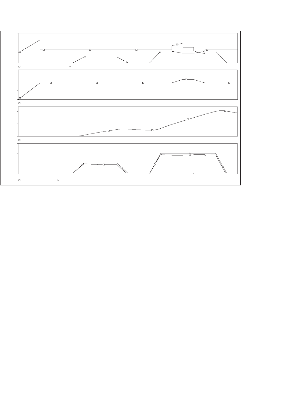
Figure 41.15 shows the results obtained for the circuit shown
in Figs. 41.12 and 41.14 with perfect tuning of the vector
controller. Perfect tuning means that the controller precisely
knows all motor parameters at all times (including resistance
changes due to heating of the windings). The two traces in
Indirect Vector Control of an Induction Motor:
Vector_Control1
Flux
Flux
Vector Controller
Omech
Torque
Torque
V_TorqueV_Flux
PARAMETERS: PARAMETERS:
V_LL = 208
V_PH_PK = {Sqrt(2)*V_LL/sqrt(3)}
PSI_N = {V_ph_pk/Omega_n}
FREQ_N = 60
OMEGA_N = {2*Pi*Freq_n}
Pl = 3.14159265
Omega_mech
Motor1
DD
QQ
Torque
Omech
Induction_Servo
Ratio = 0.5
24.5 Nm @
880 RPM
Lin_Load1
Gear1
FIGURE 41.14 Circuit for indirect vector control without ABC–DQ transformations.
the diagram on top of Fig. 41.15 represent the traces for the
D and Q input signals of the vector rotator. The graph below
shows the reference value for the flux. It is evident, that the
flux level is being changed at the same time when 10 Nm of
torque is commanded (and produced). This is done to check if
the torque and the flux can be independently controlled, which
is true for correct FOC. Below the flux reference is the graph
for the mechanical angular velocity. It can be seen, that the
machine accelerates whenever torque is developed and slows
down due to the load when the torque command is driven
to zero. The graph on the bottom of Fig. 41.15 provides the
easiest way to judge the quality of the correct field orientation.
This graph shows the traces of the commanded and the actu-
ally produced torque and in this case they are perfectly on top
of each other at all times.
41 Computer Simulation of Power Electronics and Motor Drives 1135
20V
10V
0V
750mV
500mV
250mV
0V
50V
25V
0V
15V
10V
5V
0V
0s 0.4s
V (Motor1: Torque)
V (Torque)
V (Omega_mech)
V (Flux)
V (Vector_Contr 1.I_sd) V (Vector_Contr I1.I_sq)
Current Command ID, 1V=1A
Current Command IQ, IV=1A
Flux Reference, 1V=1Vs
Mechanical Angular Velocity, 1V=1rad/s
Torque & Torque Command
0.8s
Time
1.2s 1.6s 2.0s
SEL〉〉
FIGURE 41.15 Results for indirect vector control with perfect tuning.
Figure 41.16 is an example of the results obtained from a
de-tuned vector controller. The circuit is identical to the cir-
cuit in Fig. 41.12, except for the fact that the rotor resistance
value in the controller was increased to 125%, which is thought
to be attributed to heating of the rotor bars. It is obvious
that the traces for the commanded and the actually produced
torque are no longer identical. This is especially true, during
times when the flux is changing. De-tuning is actually a real
problem in industrial vector control applications. De-tuning
is caused by the fact that the machine parameters are not pre-
cisely known to begin with and/or, are changing during the
operation of the machine. The values of the winding resistance
are most likely to change due to heating of the machine.
41.6 Simulation of Sensorless Vector
Control Using PSpice
®
In the previous example, the advantages of vector control have
been shown. However, for the implementation of the control
scheme a sensor for the mechanical speed was necessary. This
could pose a problem for applications, where a vector control
unit is to be retrofitted into existing equipment. The motor
installation may not easily allow the installation of a mechan-
ical speed sensor. Therefore engineers have thought to replace
the mechanical speed sensor with a speed observer, which is
a mathematical model that is evaluated by the control pro-
cessor (typically a DSP), which is performing the standard
vector control computations anyway. The algorithm for the
observer would use the measured stator voltages and currents
for the D- and Q-axes as input parameters. It would also rely
on the knowledge of the machine model and on the correct
machine parameters (rotor and stator resistance, mutual and
leakage inductance, etc.). The following example shows such
an arrangement. It could be derived from the previous exam-
ple with the only difference being that the speed sensor signal
is replaced by a speed observer. However, careful examina-
tion of the derivation [2] of the speed observer reveals, that it
is easier to calculate the synchronous angular velocity, which
is ultimately desired anyway, than the angular velocity of the
rotor. Therefore, the observer was modified and the calcula-
tion of the rotor speed and the subsequent addition of the slip
speed was foregone. The speed observer used here basically
solves the D, Q equation system of the induction machine
shown in Eq. (41.3), with the only difference that some of
the dependent variables are now independent and vice versa.
In addition to the synchronous angular velocity, the observer
1136 M. Giesselmann
20V
10V
0V
SEL〉〉
750mV
500mV
250mV
0V
50V
25V
0V
15V
10V
5V
0V
0s 0.4s
V (Motor1:Torque) V (Torque)
Torque & Torque Command
Mechanical Angular Velocity, 1V=1rad/s
Flux Reference, 1V=1Vs
Current Command ID, 1V=1A
V (Vector_ContrI1.I_sd)
V (Vector_ContrI1.I_sq)
Current Command IQ, 1V=1A
V (Flux)
V (Omega_mech)
0.8s 1.2s 1.6s 2.0s
Time
FIGURE 41.16 Results for indirect vector control with 125% rotor resistance.
provides the values of the rotor flux, which are used in the
D-axis signal path. The advantage of this is that the compen-
sator with the differentiation function, which is problematic
from a numerical stability standpoint, can be eliminated.
Figure 41.17 shows the top level of a simulation project
for sensorless vector control. The top view of this circuit
is very similar to the circuit for the indirect vector control
represented by Figs. 41.12 and 41.14 except for the miss-
ing motor-speed feedback. The model for the motor and the
motor’s parameters are precisely the same as in the example
for the indirect vector control. Selecting the “Sensorless Vector
Control” block and choosing “Descend Hierarchy” reveals the
associated subcircuit, which is shown in Fig. 41.18. This sub-
circuit is similar to the subcircuit for the indirect vector control
with two exceptions: first and foremost, the motor-speed feed-
back signal is replaced by the speed observer. In this case
the speed observer directly provides the synchronous angular
velocity. Therefore, it is not necessary to calculate the slip speed
and add it to the rotor speed to obtain the synchronous speed.
Second, the values of the rotor flux, which are available from
the speed observer, are used to calculate the reference value
for the torque producing current (Q) component. Therefore,
the compensation term, which contains a differentiator in the
D-axis of the controller shown in Fig. 41.13 can be eliminated.
The purpose of the compensation term is to ensure that the
flux is equal to the flux command at all times with no delay.
If that is assured, the command signal can be chosen in place of
the real flux to calculate how much torque producing current
is necessary to obtain the desired torque.
In order to demonstrate how to obtain a more compact
motor model, the extensive subcircuit of the induction motor
model (see Fig. 41.9) has been replaced by a number of addi-
tional attributes which have been added to the motor symbol
using the symbol editor.
However, if the actual flux is known (observed), this value
can be used instead. Since the flux observer is fed by the
D- and Q-axes voltages and currents for the stationary ref-
erence frame, the flux components need to be transformed
back into the synchronous reference frame. This is done with
the “Negative Vector Rotator” located above and to the left of
the speed observer in Fig. 41.18.
The easiest way to start the symbol editor and to open the
appropriate library is to select the symbol by clicking into it
and then select the “Edit Symbol” function. The additional
attributes of the modified motor symbol will enter the equiv-
alent to the subcircuit represented by Fig. 41.9 into the netlist.
The netlist is a compilation of the schematic pages into a
textual description in ASCII format. From a usability stand-
point, a “self-contained” symbol like this is a very elegant
solution, since the file for the subcircuit is no longer required.
41 Computer Simulation of Power Electronics and Motor Drives 1137
Sensorless Vector Control of an Induction Motor
Flux
Reference
Flux
Flux
DA
Va
Vb
Vc
B
C
A
B
C
Q
D
Q
D
Motor 1
Rt 1k
Torque
Omech
Lin_Load1
12.25 Nm @
1760 RPM
Q
D
Q
V_Flux
NoSen_Vec_Control1
Sensorless Vector Control
Torque
PARAMETERS: PARAMETERS:
FREQ_N = 60
OMEGA_N = {2*Pi*Freq_n}
PI = 3.14159265
V_LL = 220
V_PH_PEAK = {sqrt(2)*V_LL/sqrt(3)}
PSI_N = {V_ph_peak/Omega_n}
Torque
++
−−
V_Torque
FIGURE 41.17 Top level of simulation circuit for sensorless vector control.
Flux
Torque
PsiD
PsiQ
{1/@LM}
I_sd
I_sq
Isd
I_d
Isq
V(%IN)
V(%IN)
Controller for Sensorless Vector Control:
Speed Observer
V(%IN1)
/
(@KT*V(%IN2)
+10n)
Rt1
1k
Speed_Observer1
V_d
I_sd
I_sq
V_q
I_d
I_q
V_q
V_d
In_D
Out_D
Out_Q
Rho
In_Q
Vec Rot -
In_D
Out_D
Out_Q
Rho
In_Q
Vec Rot +
Psi_d
PsiD
I_q
V_d
D
Q
V_q
Psi_xr
OmSync
Psi_mag
Psi_q
PsiQ
1k
Rt3
1k
Rt2
0v
1.0
FIGURE 41.18 Subcircuit for sensorless vector controller.
1138 M. Giesselmann
Since the PSpice
simulation engine always uses the netlist
as the input, the circuit works identically. For the PSpice
sim-
ulation it makes no difference, where the netlist or part of it
comes from. This also means that even the most recent release
of PSpice
can still simulate legacy files that have been created
before the introduction of schematic editors. The introduc-
tion of netlist entries is done via the “TEMPLATE” attribute.
This attribute is a system attribute and a part of every symbol.
Therefore, the TEMPLATE attribute is of course present in the
attribute list for the motor symbols in the previous examples.
These attribute lists are shown in Tables 41.1 and 41.2. In these
tables the TEMPLATE attribute has no value since the netlist
The format of the netlist entries for some common elements is:
[] denotes space holder for name extension specific for a symbol to avoid duplicate names.
Resistors, (R devices):
Generic: Rname[] +Node[] −Node[] Value ;Optional Comment
Example: Rsd[] Rsd+[] Rsd−[] 1.0k ;Resistor, fixed Value
Example: Rsd[] Rsd+[] Rsd−[] {@Rs} ;Resistor, Value Rs passed on
Example: Rsd[] %D 0 1.0k ;Resistor, 1k, Pin ‘D’ to Gnd
Inductors, (L devices):
Generic: Lname[] +Node[] −Node[] Value ;Optional Comment
Example: Lsd[] Lsd+[] Lsd−[] 1.0u ;Inductor, 1.0 mH fixed
Example: Lsd[] Lsd+[] Lsd−[] {@Lsl} ;Inductor, Value Lsl passed on
Voltage-controlled voltage sources (E devices):
Generic: Ename[] +Out[] −Out[] VALUE { Control Function }
Example: ETorque[] %Torque 0 VALUE { 1.5
∗
(Vt1[] – Vt2[]) }
;E source, output between pin “Torque” and Gnd, Control function as shown
FIGURE 41.19 Screen view of motor symbol in the symbol editor.
entries are made by the symbols in the associated subcircuit.
To give a reader a better understanding of the self-contained
machine symbol, the format of some common netlist entries
and the syntax of the value of the TEMPLATE attribute is
discussed. It is also very helpful to examine the TEMPLATE
attributes of existing symbols.
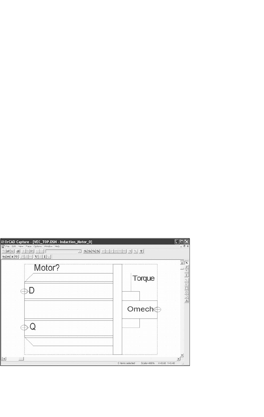
Figure 41.19 shows the screen view of the symbol for the
induction motor in the symbol editor in PSpice
/Cadence
Release 9.1, which was used for the development of this part.
Figure 41.20 shows a similar view; however, here the window
for entry and editing of attributes is also visible. This screen
can be invoked using the “Options/Part Properties...” dialog.