Pecharsky V.K., Zavalij P.Y. Fundamentals of Powder Diffraction and Structural Characterization of Materials
Подождите немного. Документ загружается.


Preliminary data processing and phase analysis
391
12.H.M. Berrnan, T. Battistuz, T.N. Bhat, W.F. Bluhm, P.E. Bourne,
K.
Burkhardt,
Z.
Feng, G.L. Gilliland,
L.
Iype,
S.
Jain, P. Fagan, J. Marvin,
D. Padilla,
V.
Ravichandran, B. Schneider,
N.
Thanki, H. Weissig, J.D.
Westbrook, and C. Zardecki, The Protein Data Bank, Acta Cryst. D58,
899
(2002).
13.H.M. Berman, J.D. Westbrook, Z. Feng,
L.
Iype, B. Schneider, and C.
Zardecki, The Nucleic Acid Database, Acta Cryst. D58, 889 (2002).
392
Chapter
4
4.6
Problems
Answers to all problems listed below are located in the file Chapter-4-
Problems-Solutions.pdf on the CD accompanying this book.
1.
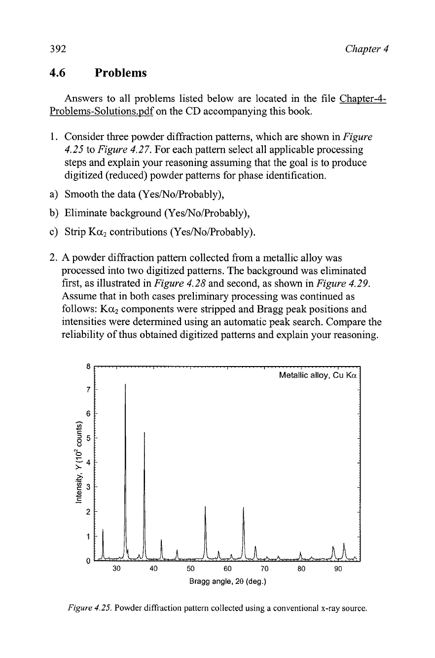
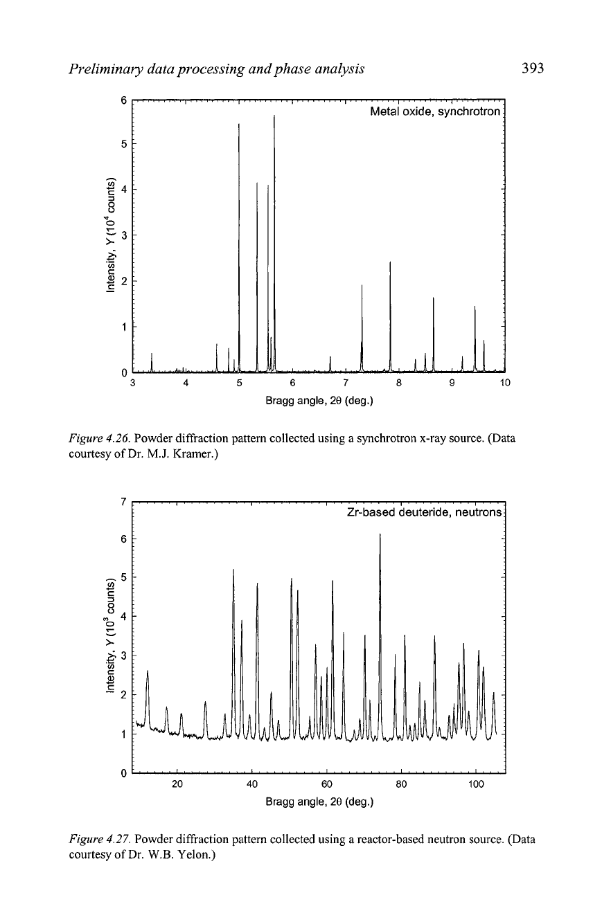
Consider three powder diffraction patterns, which are shown in
Figure
4.25
to
Figure
4.27.
For each pattern select all applicable processing
steps and explain your reasoning assuming that the goal is to produce
digitized (reduced) powder patterns for phase identification.
a) Smooth the data (Yes/No/Probably),
b) Eliminate background (Yes/No/Probably),
c) Strip
Ka2
contributions (Yes/No/Probably).
2.
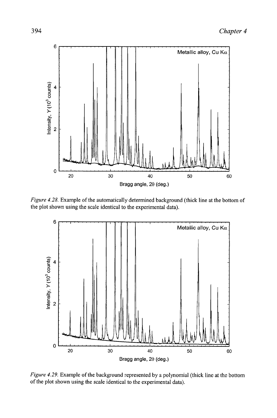
A powder diffraction pattern collected from a metallic alloy was
processed into two digitized patterns. The background was eliminated
first, as illustrated in
Figure
4.28
and second, as shown in
Figure
4.29.
Assume that in both cases preliminary processing was continued as
follows:
Ka2
components were stripped and Bragg peak positions and
intensities were determined using an automatic peak search. Compare the
reliability of thus obtained digitized patterns and explain your reasoning.
40 50
60
70
80
90
Bragg angle,
28
(deg.)
Figure
4.25.
Powder diffraction pattern collected using a conventional x-ray source.
Preliminary data processing and phase analysis
393
Bragg angle,
29
(deg.)
Figure
4.26.
Powder diffraction pattern collected using a synchrotron x-ray source. (Data
courtesy of Dr.
M.J.
Kramer.)
Figure
4.27.
Powder diffraction pattern collected using a reactor-based neutron source. (Data
courtesy of Dr.
W.B.
Yelon.)
Chapter
4
I
~etailic alloy,
Cu
KCL
20 30 40 50 60
Bragg angle, 20 (deg.)
Figure
4.28.
Example of the automatically determined background (thick line at the bottom of
the plot shown using the scale identical to the experimental data).
20
30 40 50 60
Bragg angle, 20 (deg.)
Figure
4.29.
Example of the background represented by a polynomial (thick line at the bottom
of the plot shown using the scale identical to the experimental data).
Preliminary data processing and phase analysis
395
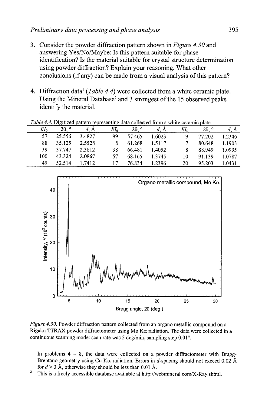
3.
Consider the powder diffraction pattern shown in
Figure
4.30
and
answering Yes/No/Maybe: Is this pattern suitable for phase
identification? Is the material suitable for crystal structure determination
using powder diffraction? Explain your reasoning. What other
conclusions (if any) can be made from a visual analysis of this pattern?
4.
Diffraction data'
(Table
4.4)
were collected from a white ceramic plate.
Using the Mineral Database2 and
3
strongest of the
15
observed peaks
identify the material.
Table
4.4.
Digitized pattern representing data collected from a white ceramic plate.
111,
20,"
d,A I/Io
20,
"
d,
A
I/I0
20,
O
d,
A
57 25.556
3.4827 99
57.465 1.6023 9
77.202 1.2346
88
35.125 2.5528
8 61.268
1.5117 7
80.648 1.1903
39 37.747
2.3812 38
66.481 1.4052 8
88.949 1.0995
100 43.324
2.0867 57
68.165 1.3745 10
91.139 1.0787
49 52.514
1.7412
17
76.834 1.2396
20
95.203 1.0431
Bragg angle,
28
(deg.)
Figure
4.30.
Powder diffraction pattern collected from an organo metallic compound on a
Rigaku TTRAX powder diffractometer using Mo
Ka
radiation. The data were collected in a
continuous scanning mode: scan rate was
5
deg/min, sampling step
0.01".
'
In problems
4
-
8,
the data were collected on a powder diffractometer with Bragg-
Brentano geometry using Cu Ka radiation. Errors in d-spacing should not exceed
0.02
8,
ford
>
3
A,
otherwise they should be less than
0.01
A.
This is a freely accessible database available at
http://webmineral.corn/X-Ray.shtm1.
396
Chapter
4
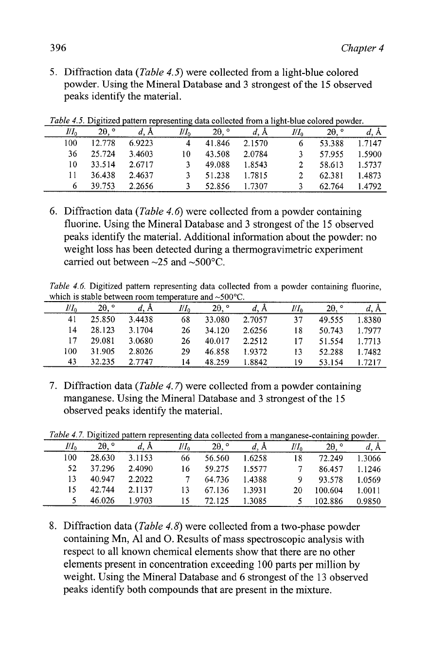
5.
Diffi-action data
(Table
4.5)
were collected from a light-blue colored
powder. Using the Mineral Database and 3 strongest of the
15
observed
peaks identify the material.
Table
4.5.
Digitized pattern representing data collected from a light-blue colored powder.
111,
20,
"
d,
A
111,
20,
"
d,
8,
111,
20,
"
d,
A
100 12.778
6.9223 4
41.846
2.1570 6
53.388 1.7147
36 25.724
3.4603 10
43.508
2.0784 3
57.955 1.5900
10 33.514
2.6717 3
49.088 1.8543
2 58.613 1.5737
11 36.438
2.4637 3
51.238 1.7815 2 62.381 1.4873
6 39.753 2.2656 3 52.856 1.7307 3 62.764 1.4792
6. Diffraction data
(Table
4.6)
were collected from a powder containing
fluorine. Using the Mineral Database and
3 strongest of the 15 observed
peaks identify the material. Additional information about the powder: no
weight loss has been detected during a thermogravimetric experiment
carried out between
-25
and -500•‹C.
Table
4.6.
Digitized pattern representing data collected from a powder containing fluorine,
which is stable between room temperature and
-500•‹C.
-
111,
20,"
d,8,
IlI,
20,
"
d,
A
IlI,
20,
"
d,
A
41
25.850 3.4438
68 33.080
2.7057
37 49.555
1.8380
7.
Diffraction data
(Table
4.7)
were collected from a powder containing
manganese. Using the Mineral Database and 3 strongest of the 15
observed peaks identify the material.
Table
4.7.
Digitized pattern representing data collected from a manganese-containing powder.
Illo
20,
"
d,
A
IlI,
20,
"
d,
A
111,
20,
O
d, 8,
100 28.630 3.1 153 66 56.560 1.6258 18 72.249 1.3066
52 37.296 2.4090 16 59.275 1.5577 7 86.457 1.1246
13 40.947 2.2022 7 64.736 1.4388 9 93.578 1.0569
15 42.744 2.1 137 13 67.136 1.3931 20 100.604 1.0011
5 46.026 1.9703 15 72.125 1.3085 5 102.886 0.9850
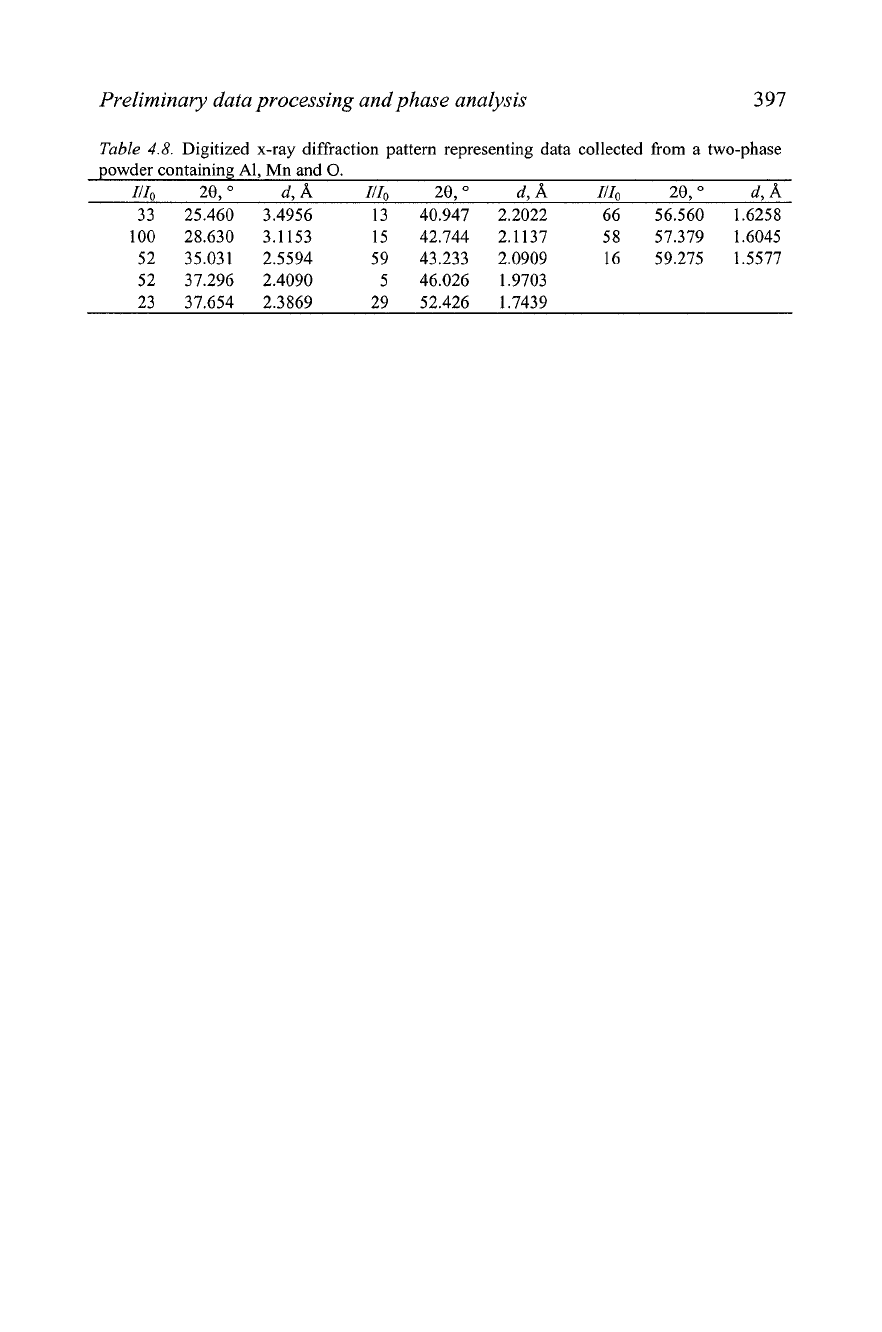
Diffraction data
(Table
4.8)
were collected from a two-phase powder
containing Mn, A1 and
0.
Results of mass spectroscopic analysis with
respect to all known chemical elements show that there are no other
elements present in concentration exceeding 100 parts per million by
weight. Using the Mineral Database and
6 strongest of the
13
observed
peaks identify both compounds that are present in the mixture.
Preliminary data processing and phase analysis
3
97
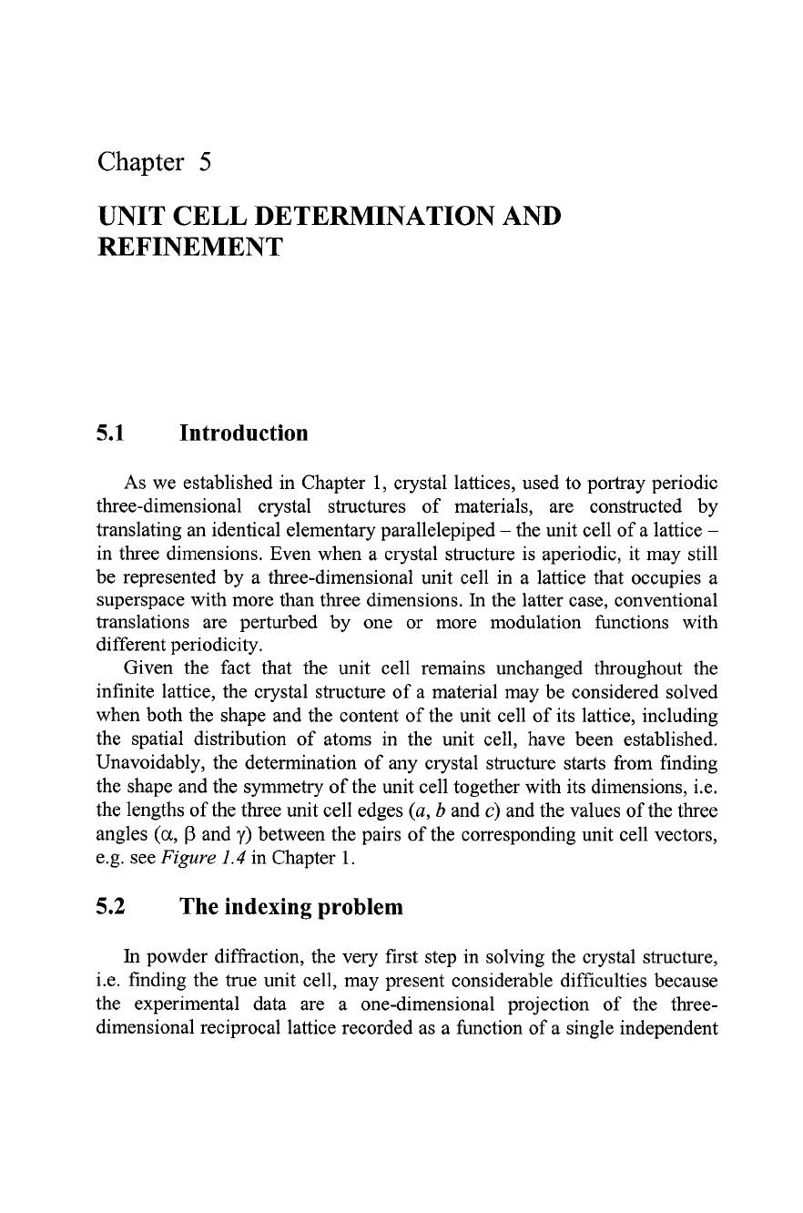
Table
4.8.
Digitized x-ray diffraction pattern representing data collected from a two-phase
powder containing Al, Mn and
0.
ZIZo
20,
d,
A
ZIZo
29,
O
d,
A
IIZo
20,
"
d,
A
33 25.460 3.4956 13 40.947 2.2022 66 56.560 1.6258
Chapter
5
UNIT CELL DETERMINATION AND
REFINEMENT
5.1
Introduction
As we established in Chapter 1, crystal lattices, used to portray periodic
three-dimensional crystal structures of materials, are constructed by
translating an identical elementary parallelepiped
-
the unit cell of a lattice
-
in three dimensions. Even when a crystal structure is aperiodic, it may still
be represented by a three-dimensional unit cell in a lattice that occupies a
superspace with more than three dimensions.
In
the latter case, conventional
translations are perturbed by one or more modulation functions with
different periodicity.
Given the fact that the unit cell remains unchanged throughout the
infinite lattice, the crystal structure of a material may be considered solved
when both the shape and the content of the unit cell of its lattice, including
the spatial distribution of atoms in the unit cell, have been established.
Unavoidably, the determination of any crystal structure starts from finding
the shape and the symmetry of the unit cell together with its dimensions,
i.e.
the lengths of the three unit cell edges
(a,
b
and
c)
and the values of the three
angles
(a,
P
and
y)
between the pairs of the corresponding unit cell vectors,
e.g. see
Figure
1.4
in Chapter 1.
5.2
The
indexing problem
In
powder diffraction, the very first step in solving the crystal structure,
i.e. finding the true unit cell, may present considerable difficulties because
the experimental data are a one-dimensional projection of the three-
dimensional reciprocal lattice recorded as a function of a single independent
400
Chapter
5
variable
-
the Bragg angle. Thus, the directions are lost and only the lengths
of the reciprocal lattice vectors are measurable in a powder diffraction
experiment. This is quite different from scattering by a single crystal where
both the length and direction of each vector in reciprocal space are
preserved, provided the intensity of a corresponding Bragg peak exceeds the
background and is measurable.
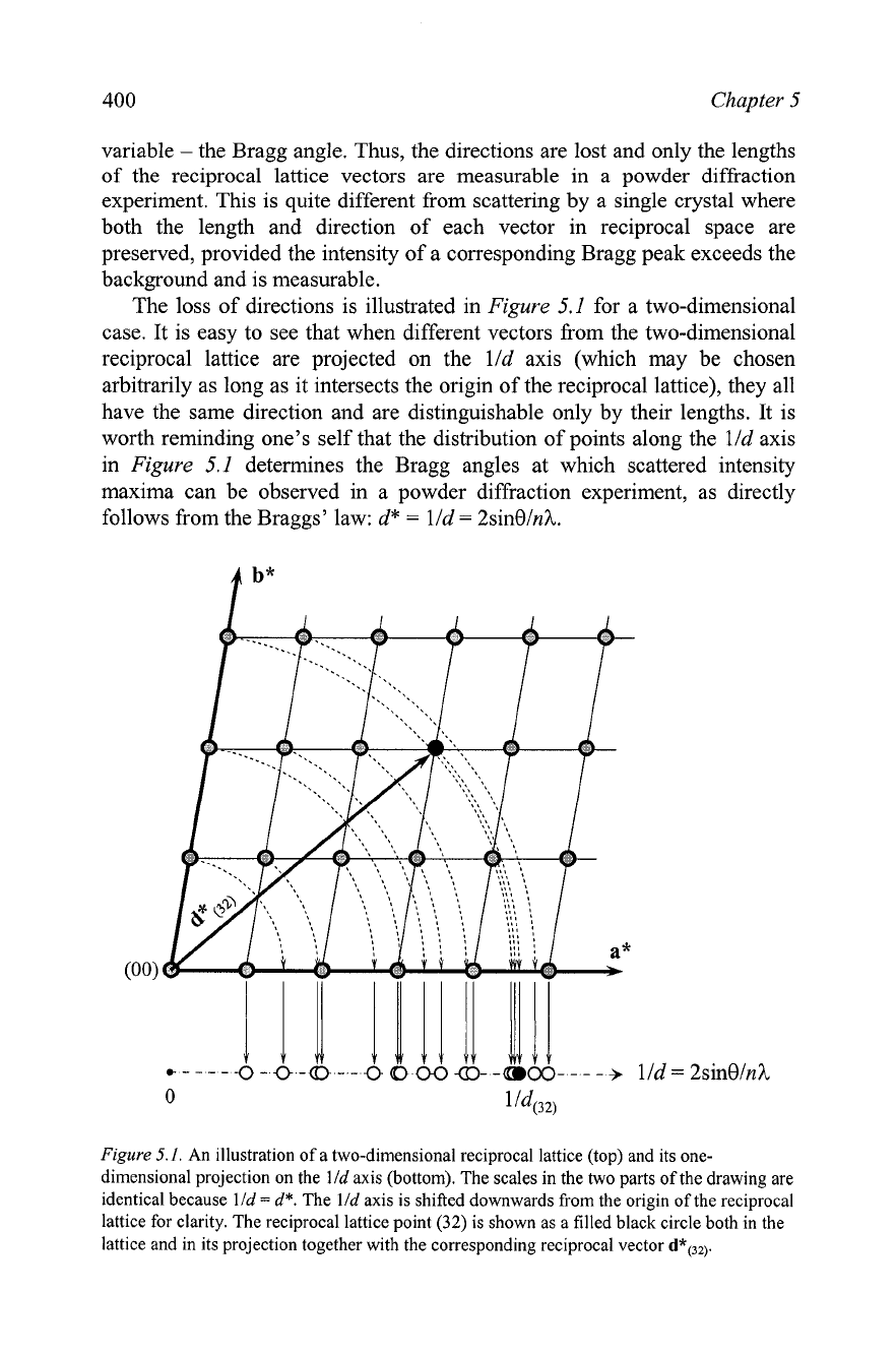
The loss of directions is illustrated in
Figure
5.1
for a two-dimensional
case. It is easy to see that when different vectors from the two-dimensional
reciprocal lattice are projected on the lld axis (which may be chosen
arbitrarily as long as it intersects the origin of the reciprocal lattice), they all
have the same direction and are distinguishable only by their lengths. It is
worth reminding one's self that the distribution of points along the
lld axis
in
Figure
5.1
determines the Bragg angles at which scattered intensity
maxima can be observed in a powder diffraction experiment, as directly
follows from the
Braggs' law: d*
=
lld
=
2sinOlnI.
lld
=
Figure
5.1.
An illustration of a two-dimensional reciprocal lattice (top) and its one-
dimensional projection on the
lld
axis (bottom). The scales in the two parts of the drawing are
identical because
lld
=
d*.
The
lld
axis is shifted downwards from the origin of the reciprocal
lattice for clarity. The reciprocal lattice point
(32)
is shown as a filled black circle both in the
lattice and in its projection together with the corresponding reciprocal vector
d*(32).
Unit cell determination and refinement
40
1
Regardless of the nature of the diffraction experiment, finding the unit
cell in a conforming lattice is a matter of selecting the smallest
parallelepiped in reciprocal space, which completely describes the array of
the experimentally registered Bragg peaks. Obviously, the selection of both
the lattice and the unit cell should be consistent with crystallographic
conventions (see section 1.12, Chapter
I), which impose certain constraints
on the relationships between unit cell symmetry and dimensions.
Since each point in reciprocal space represents a series of
crystallographic planes, the description of diffraction data by means of any
lattice may therefore, be reduced to assigning triplets of Miller indices to
every observed Bragg peak based on the selected unit cell. Recalling the
definitions of both the direct and reciprocal lattices (Eqs. 1.1 and 1.16,
respectively) and considering Figure
5.1
(or Figure
2.40
in Chapter
2,
which
illustrates a three-dimensional case), the assignment of indices in a periodic
lattice is based on Eq. 5.1.' The latter establishes relationships between the
unit vectors
a*,
b* and
c*
and the corresponding reciprocal vectors d*(jko in
terms of triplets of integers
h,
k
and I.
d*,,
=
ha*
+
kb*
+
lc*
(5.1)
This process is commonly known as indexing of diffraction data and in
three dimensions it usually has a unique and easy solution when both the
lengths and directions of reciprocal vectors,
d*jkl, are available. On the
contrary, when only the lengths,
d*hkl, of the vectors in the reciprocal space
are known, the task may become extremely complicated, especially if there
is no additional information about the crystal structure other than the array of
numbers representing the observed l/djkl
[=
d*hkl] values.
The difficulty and reliability of indexing are closely related to the
absolute accuracy of the array of d*jkl values, i.e. to the absolute accuracy
with which positions of Bragg reflections have been determined. For
Conventional lattices may be perturbed by functions with different periodicity, e.g. by
sinusoidal or saw-tooth-like modulations, see section 1.21 in Chapter
1.
In the simplest
case (one-dimensional modulation), Eq.
5.1
becomes
d*hkr
=
ha*
+
kb*
+
lc*
+
mq
assuming that the perturbation function is periodic and has the modulation vector
q.
In a
case of three-dimensional modulation, a total of six indices
(h, k,
1,
m, n,
and
p)
are
required to identify every point observed in reciprocal space:
d*hkl
=
ha*
+
kb*
+
lc*
+
mq,
+
nq2
+
pq,,
where
q,, q2
and
q3
are the modulation vectors of the corresponding
perturbation functions. If this is the case, vectors
q,, q2
and
q3
should be established in
addition to
a*,
b*
and
c*
before assignment of indices can be performed. Since even the
three-dimensional diffraction pattern of a modulated structure is a projection of four- to
six-dimensional superspace, indexing of single crystal diffraction data is quite complex. It
is rarely, if ever, successful from first principles when only powder diffraction data are
available.
