Novak P. Developments in hydraulic engineering - Vol. 5
Подождите немного. Документ загружается.

Limit values of the cavitation coefficient σ for a safe design are given as a function of
specific speed. Evaluation of in situ experiences and much research work has contributed
to the clarification of this subject.
97–102
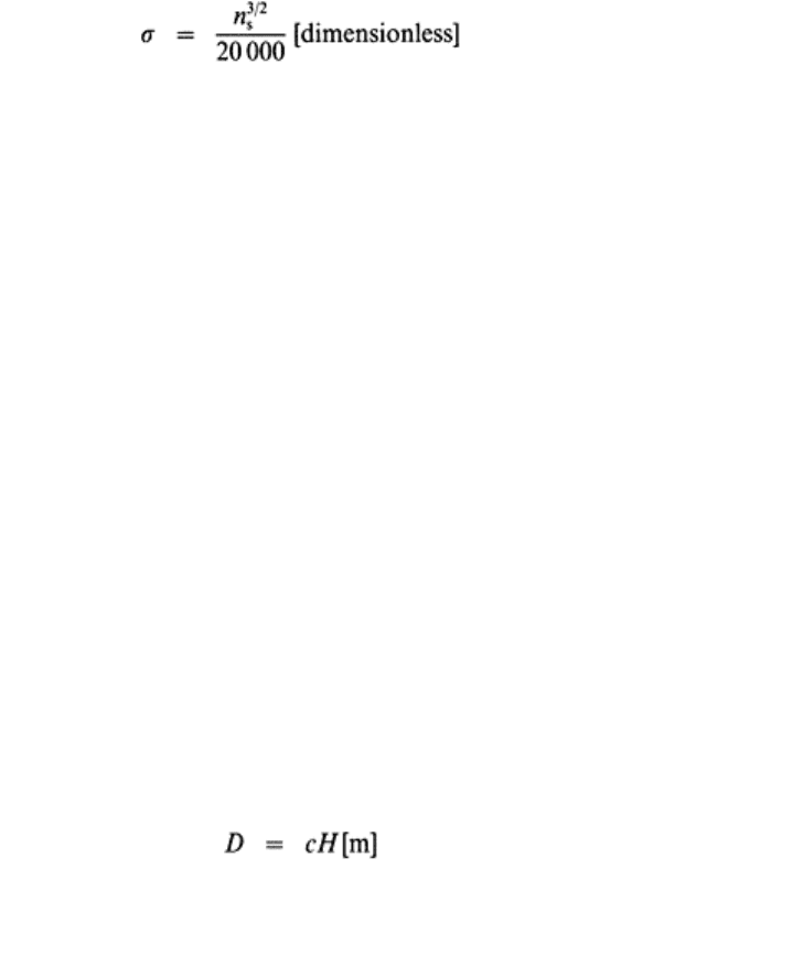
The author’s recommendation for the first stage of
planning for conventional Kaplan turbines is
103
(46)
which can be lowered for propeller wheels by about 8–10%, and also reduced by a few %
for tubular machines.
In most cases, it is economical to make full use of the limit given by eqn (46); under
particular conditions, however, lower n
s
and, accordingly, lower n values are selected.
The author uses for the design based on the permissible maximum n
s
the term ‘limit
design’.
Whatever the result of a calculation for operational speed, for the design the next
synchronous speed has to be chosen as the unit can be connected to the grid only when it
rotates with any of the speeds to be gained from eqn (27) by substituting whole numbers
for p
p
.
In an emergency caused by a sudden load rejection (i.e. when the generator is
disconnected from the grid) the unit, assuming that the flow through the turbine is
constantly and continuously maintained, accelerates up to the runaway speed. The highest
runaway speed can develop at the highest head and full gate opening. At runaway speed
the unit gets into a hydromechanical equilibrium and rotates without producing useful
power. The runaway speed of axial machines may reach 2–3·5 times higher values than
the rated speed. Since, in most cases, it is not reasonable to dimension the machines (both
turbine and generator) and the bearings for runaway speed, various measures have been
devised and successfully applied to prevent runaway (see Section 7.4.1).
7.3.4 Runner Diameter
Since the general design of the powerhouse, presuming that the number of units has been
already decided, depends mainly on the setting elevation (defined by h
s
) and the runner
diameter, it is advisable to have an approximate estimate on the latter too.
Several proposals are known from the literature, expressing the runner diameter D
alternatively as a function of Q, H, n, n
s
(Ahlfors, 1926; Pantell, 1933; Finnicome, 1940;
Nesteruk, 1946; Berejnoy, 1948;
102
de Siervo and de Leva
95
). For the preliminary phase
of planning the author suggests a simple relation valid only for the limit design:
103
(47)
where the following values may be substituted for the diameter coefficient c:
(a) Conventional Kaplan turbines
Water power development: low-head Hydropower utilization 69
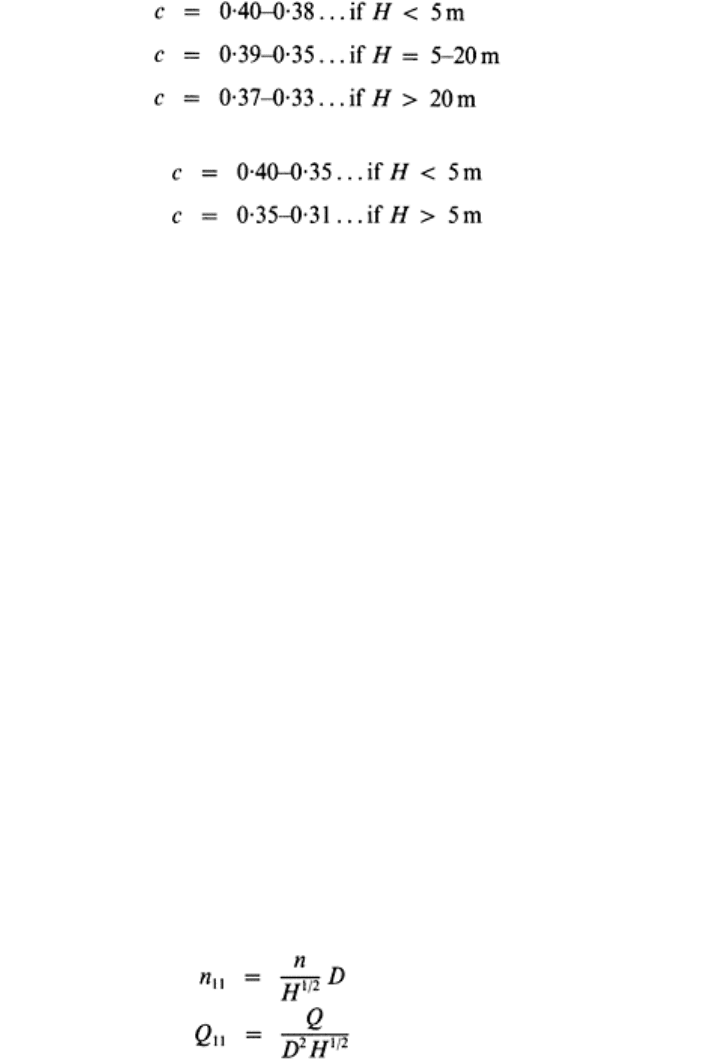
(b) Tubular turbines
With more conservative solutions, i.e. when choosing significantly lower n
s
and n values
than those pertaining to the limit designs, the diameter is larger.
Very large Kaplan turbines have already been constructed, e.g. D=9·5 m (at Iron Gate,
see Fig. 9).
Finally, it has to be repeated that the above recommendations concerning the limit
magnitudes of h
s
, σ, n
s
and D are only general estimates for preliminary planning and
feasibility studies. Manufacturers have their own designs, based on research and model
tests, which have to be accepted for the final proposals.
7.3.5 Operation under Varying Head, Efficiency-Hill Diagram
If the head varies considerably, which is mostly the case with low-head plants, the
determination of the operational characteristics of the turbine to be installed is not as
simple as has previously been described, e.g. the efficiency curves in Figs 48 and 49 are
valid for a single selected head only. With decreasing head efficiency diminishes and σ
c
grows. The efficiency also drops when the head increases, but then σ
c
decreases.
The performance characteristics of turbines over a wide range of discharge (or power
output) and head can be obtained from the efficiency-hill diagrams, plotted on the basis
of extensive tests on model turbines. The results are valid, with slight corrections due to
scale effect, for homologous designs of any absolute dimension. Hence the performance
of the prototype can be predicted from the operational characteristics or, in the case of
dimensionless formulation, from the operational constants of the selected turbine
geometry displayed by the hill diagram. Several versions of the hill diagram can be
found. The characteristics and constants are derived by using the hydromechanical
similarity laws. One procedure is presented below.
The so-called unit speed, unit discharge and unit power pertain to a particular
(fictitious) unit-diameter (1 m) turbine homologous to the tested model and operating
under unit head (1 m). These are denoted as n
11
, Q
11
and P
11
and can be derived from the
performance tests of the model. Between these unit characteristics and the corresponding
quantities (n, Q, P) of any homologous prototype of diameter D operating under a head
H, the following relationships exist:
(48)
(49)
Developments in hydraulic engineering–5 70
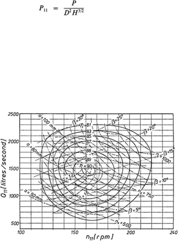
(50)
Usually n
11
, Q
11
or n
11
, P
11
are plotted. Figure 51 shows a plot in the (n
11
, Q
11
) system of
the isolines of the following parameters of a Kaplan design: efficiency (dimensionless),
wicket gate opening (a mm), runner blade setting (β°), cavitation coefficient (σ). Since,
for homologous machines, efficiency and σ according to the strict similarity theorem are
invariable, they can for the prototype be read directly from the diagram. Since, however,
the accurate prediction of efficiency, especially of its maximum value, is of great
importance, the correction (always an increment in favour of the larger prototype) is
calculated by the manufacturer. Several formulae have been suggested for efficiency
correction (taking into account the non-homologous friction losses).
104,105
For a better understanding of the performance of the model tests, the evaluation of the
hill diagram and the selection of the prototype operating point (n
11
and n) further study of
books dealing with this problem is recommended.
104,106,107
FIG. 51. Efficiency-hill diagram.
7.4 Governing
7.4.1 Flywheel Effect
The frequency of the electric power produced by the generator has to be maintained
constant and, therefore, the balance between input torque and load torque must always be
restored, if
Water power development: low-head Hydropower utilization 71
(a) input torque changes because of variation in H or Q, or
(b) resistance moment of the generator changes because of variation in network load.
An ideal design of speed governor which would allow changing the input torque without
delay, i.e. simultaneously with the load torque, cannot be realized for the following
reasons:
1. A certain (even if very small) speed change is essentially the factor tripping the speed
control process.
2. Inertia of moving masses (water and machines) introduces a delay in the follow-up of
input torque.
3. Regulation time must necessarily be increased in order to limit water hammer shocks
upon the structures and turbines.
The change in speed depends not only upon the velocity of governor response, but also
upon the flywheel effect of the revolving parts of the turbine and generator. As the
regulating device (i.e. the speed governor) cannot follow without delay fluctuations in
load condition, a rather significant flywheel effect depending upon the sensitivity of
regulation is required. The response speed of guide-vane control is limited, as mentioned
under 3.
With small machines, where the flywheel effect of the rotating part of the aggregate is
insufficient, special flywheels are employed. The usual procedure is that provision for the
necessary flywheel effect is the task of the generator manufacturer, guided by the
governor design of the turbine.
In the case of sudden load rejection, the time during which the runaway speed is
reached is the longer the greater the flywheel effect. Since, in most cases, the machines
are not designed for runaway speed, emergency installations are applied which, to avoid
disturbance of operation, respond only to a speed clearly exceeding the highest value of
the normal operational speed; some time elapses after governor response until the wicket
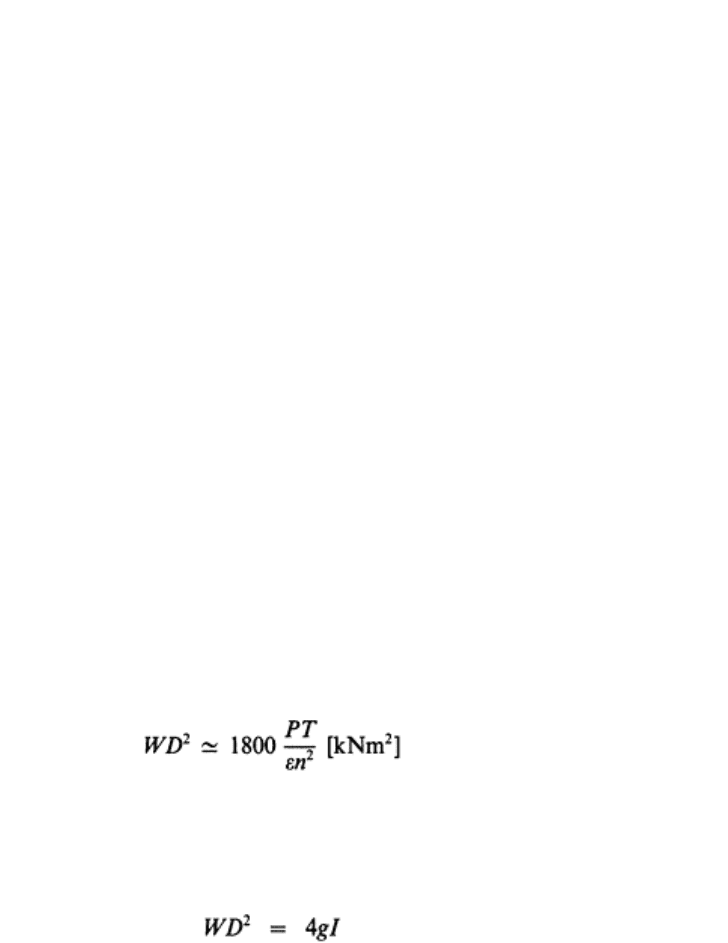
gate can be completely closed, the unit still accelerates. Thus the necessary flywheel
effect depends on the one hand on the turbine closure time and on the other on the
permissible speed increment:
(51)
where D is the diameter (m) of the generator runner, WD
2
is the flywheel effect (kN×m
2
),
P is the rated power (kW), T is the closure time(s) of the wicket gate, and ε(=∆n/n) is the
coefficient of the ∆n permissible speed increment.
The relation of the flywheel effect to the inertia momentum I of the rotating mass is
defined by
(52)
where g is the gravity acceleration. (It has to be borne in mind that W is not the weight of
the rotating mass but that of a fictitious mass assumed to be distributed on an
infinitesimally narrow strip along the perimeter of the rotor and satisfying eqn (52).)
Developments in hydraulic engineering–5 72
There are also other time values besides the wicket gate closure time which may
influence the determination of the fly wheel effect (starting time of the water column,
servomotor opening/closing time);
109
their discussion, however, is beyond the scope of
this treatise.
The primary measure for preventing runaway is the emergency fast closure of the
wicket gate during interval T (see above), actuated by the governor in the case of sudden
load rejection. Sometimes planners insist upon a second safety measure, i.e. upon
installation of a quick action emergency gate in the inlet flume, presuming the possibility
of a simultaneous sudden load rejection and wicket gate failure.
7.4.2 Principles of Regulation and Components of the Governor
Since many devices in the electric power system require stable frequency (synchronous
clocks, various types of electrical instruments) speed control of the generating units
connected to the grid is essential and the generated power has to be adjusted to the power
demand (load). The mechanism fulfilling this requirement is the governor. The speed
sensing organ of the governor is either a rotating flyball pendulum or an electronic
sensor.
The movement of the pendulum or the response of the electronic sensor is transferred
by one-step or multi-step mechanisms to the servomotor actuating the wicket gate. Thus,
by regulating the guide vanes the inflow to the runner is adjusted to the prevailing power
demand.
In double-regulated (Kaplan) turbines, the position of the runner blades (setting angle
β) is automatically co-ordinated with the wicket gate opening a (see Fig. 49) to provide
for the maximum attainable efficiency. The required adjustment of the runner, defined by
the cam-function, β=f(a), can be achieved by mechanical or electronic transmission.
The governing system (actuator) includes the following devices: speed sensor, control
valves, oil pressure tank, servomotor, regulating mechanisms for the wicket gate (cam
adjustment for Kaplan machines). Hunting of the actuator must be avoided. (For further
study of the governing system the reader is referred to the relevant literature.
109,109a,110–113
7.4.3 Speed Adjustment of the Governor, Speed Droop and Load Sharing
When the load upon the network exceeds the input power supplied by all the power
plants (hydro, thermal, nuclear) feeding the system, the frequency drops, while if the load
drops below the input power the frequency begins to rise. Accordingly, in order to
maintain frequency, the input power must be increased and diminished respectively.
Some of the power stations have the task of participating in speed regulation.
The relation between speed and wicket gate opening, established by the mechanical or
electronic sensor, is defined by an n=f(a) function which can be transferred to an n=f(P)
characteristic, termed the statism of the governor. Linear statism is attainable by adequate
design. The adjustment of the governor comprises two actions (Fig. 52(a)):
Water power development: low-head Hydropower utilization 73
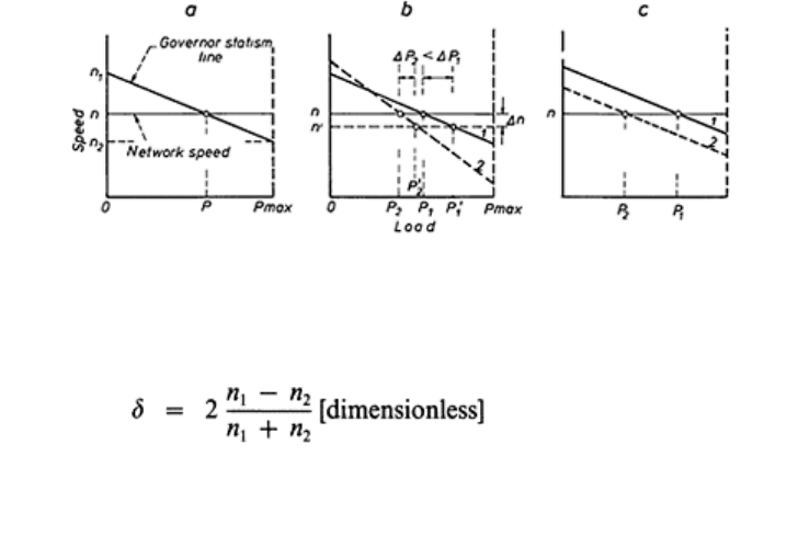
FIG. 52. Speed-droop diagrams.
1. Fixing the output (load) pertaining to the rated speed and the rated network frequency.
2. Selecting the speed range extending from the no-load condition (idle running) to full-
load operation. This is the so-called speed-droop and is defined as
(53)
Thus the droop is the ratio of the speed range to the mean value of the limiting
speeds and expresses the gradient of the statism line (sensing speed).
From the above it follows that the flatter the statism line of a unit the greater its share in
the change of load: ∆P=∆P
1
+∆P
2
(∆P
1
>∆P
2
); see Fig. 52(b). In other words, units with
small speed-droop greatly respond to frequency changes. When the statisms of two units
are parallel they produce differing powers at the network rated speed (or at any other
speed), but their share is equal in any load change; see Fig. 52(c).
Consequently, in a power system, generating units (or complete plants) with very flat
or almost zero speed-droop can be used as regulating units (plants) since they can pick up
or drop load at the smallest change in frequency, whereas the other units (plants) with
great speed-droop do not, or only slightly, react to load variations in the network. In base-
load plants the δ can be as high as 0·04–0·06. Furthermore, other units (plants) supplying
the power system can be operated by blocked load, i.e. by fixing their output in
accordance with their optimum possible operating mode (e.g. firm power by nuclear
plants) or complying with availability of their resources (e.g. natural discharge at
hydropower plants or need to satisfy irrigation demands in multi-purpose schemes).
The adjustment of the governor has to be co-ordinated with efficiency characteristics
of the turbines to operate them as efficiently as possible.
Low-head and particularly run-of-river plants are not generally used for frequency
control. In order to utilize available river flow (up to the plant discharge capacity) the
output has to be adapted to the natural hydrograph. This can be achieved by maintaining a
constant HWL. Hence the governor is actuated by a water level sensor.
114,115
A large power grid requires high-degree frequency stability. For example, in the
German Federal Republic the current directives allow only a variation of 0·05 Hz of the
standardized 50 Hz line frequency. Exceptionally, frequencies lower than 49·95 Hz occur
and, according to the rate of frequency drop, various types of emergency measures are
applied.
116
Developments in hydraulic engineering–5 74
8 ELECTRICAL EQUIPMENT
8.1 Generators and Transformers
The mechanical power output of the turbine is transformed into electric power by the
generator (alternator). In hydro-power stations three-phase synchronous a.c. machines are
generally employed. Single-phase a.c. generators are sometimes installed in plants
serving special consumers (e.g. electric railway, electro-metallurgical plants). Sometimes
d.c. generators are used to supply isolated industrial establishments.
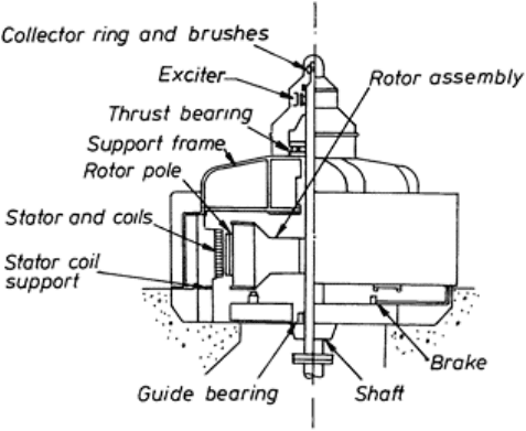
The main parts of a generator are shown in Fig. 53. The thrust bearing of a typical
vertical-axis hydro-generator (carrying the weight of the turbine runner, the axial
component of hydrodynamic loads and the generator rotor) is mounted either on top of
the head cover of the turbine, or on the lower or upper (see Fig. 53) bearing spider
(supporting frame) of the generator.
The rotor holds on its circumference the poles excited by direct current. Salient and
non-salient poles can be distinguished. The exciter current may be supplied to the coils of
the poles by d.c. machines having a common shaft with the generator, or by exciter
generators geared to the main shaft. The exciter can also be driven by an electric motor
supplied from the network, or by a small turbine installed for this purpose. In some plants
the d.c. exciting current is produced through rectifying a.c. current drawn from the
network.
The terminal output (wattous power) of a three-phase generator, for
FIG. 53. Sketch of synchronous
generator. (After C.C.Warnick.
117
)
both star and delta connections, is given by
Water power development: low-head Hydropower utilization 75
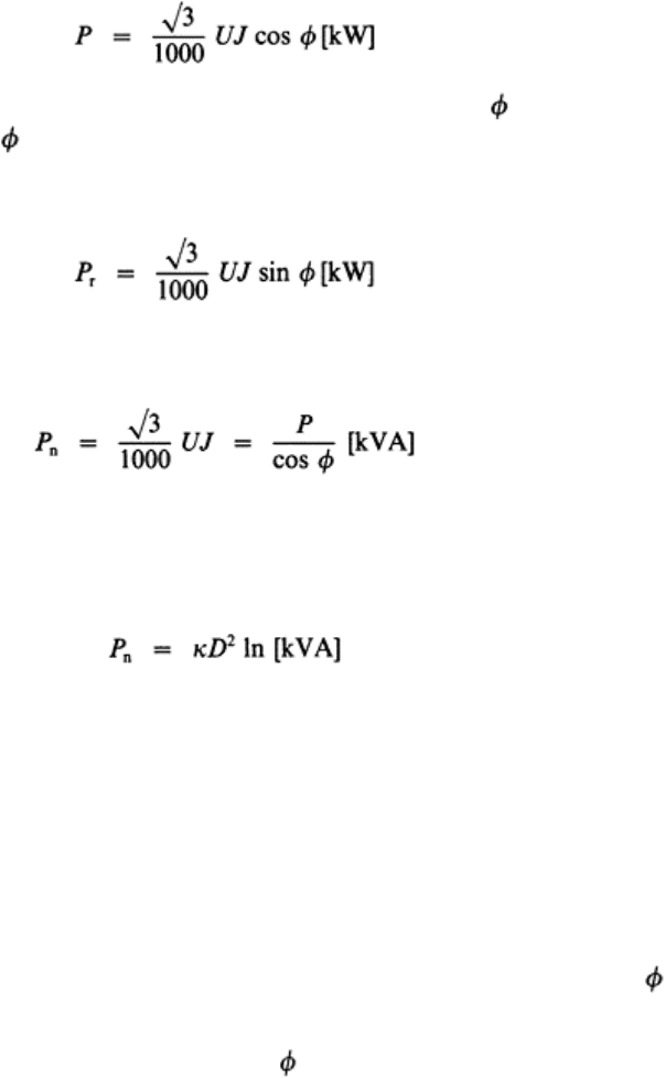
(54)
where U is the mains voltage, J is the line current (amperes),
is the phase shift angle,
and cos
is the power factor. The usual rated voltage is between 3000 and 6000 V, while
large units may be built for 10000 V; generators with rated voltage of even 20000 V or
more exist.
The generator has to feed into the network the reactive (blind) power
(55)
which is necessary to deliver magnetizing power to the network; this component,
however, does not perform useful work. Consequently the generator proper has to be
dimensioned from the apparent (nominal) power
(56)
which is expressed in kilovolt-amperes. It can easily be proved that the higher the power
factor depending on the electrical behaviour of the network (characteristics of the
consumers) the more economical are both construction and operation costs of the
generator.
The relationship between dimensions, speed and capacity is
(57)
where D is the rotor diameter (m), l is the length of the rotor body (m), n is the rated
speed (rpm), and κ is the electric compactness factor (kVA/ (m
3
×rpm)). For generators
directly coupled to conventional Kaplan turbines the usual maximum value of κ is about
5–5·5. In order to provide for sufficient flywheel moment, the rotor diameter is greater (in
most cases much greater) than the diameter of the turbine runner. With bulb arrangement
the generator size is limited by hydraulic and economic criteria so that the bulb outer
diameter should not exceed about 1·2 times the turbine runner diameter, thus permitting a
rotor diameter about equal to the runner.
118
Equation (57) shows that in the case of a very
low head insertion of a speed increasing gear may be favoured for economic reasons.
Electric power systems have usually inductive (positive) resistance characterized by
lagging power factor (the current lags behind the voltage), related to positive
. Very
exceptionally (e.g. during Sunday nights in winter) the opposite state in a grid may
develop: capacitive resistance requiring condensers or generation performance with
leading power factor, i.e. with negative
.
The main sources of power losses in the a.c. generator are: d.c. power consumption for
excitation and cooling, copper losses in the armature (stator) and rotor windings, friction
and windage losses, core losses in the magnetic circuits. The overall efficiency of the
Developments in hydraulic engineering–5 76
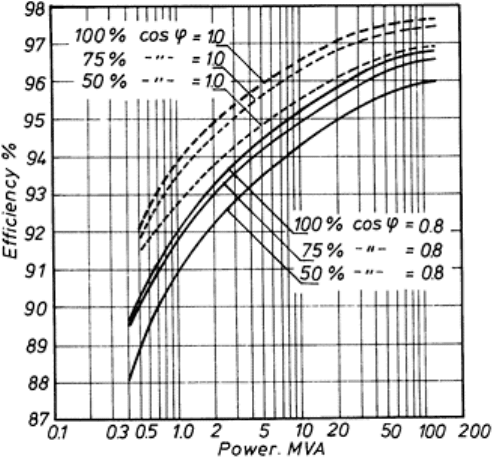
generator mainly depends on its rated (nominal) power, on the relative load and on the
power factor (Fig. 54).
In low capacity machines free-cooling systems are frequently used. In high-powered
units, on the other hand, closed air coolers fed with fresh air or closed-circuit systems are
installed.
The design of the generator brake is based on the operational torque and flywheel
moment.
In small-capacity plants, to a great extent, horizontal axis (Fig. 19) or inclined axis
outside (i.e. not bulb) generators are installed and, to reduce costs, they are frequently of
the induction type.
117,119
The simpler induction generator has no excitation; it draws the
requisite reactive power from the grid and, consequently, draws down the system voltage.
The electric current is conducted from the generator stator to the bus bar system by
means of insulated cables or bus conductors, with the
FIG. 54. Generator efficiency as a
function of rated power, relative load
and power factor.
insertion of power switches and disconnecting switches;
120,121
the circuit breakers are
used to open or close electrical circuits under high-load currents, while the disconnecting
switches are installed primarily to isolate dead lines or equipment from buses of live
apparatus. Single and double bus systems can be distinguished. The double bus system
used frequently in major plants ensures full freedom of switching operations during
generator failures or other incidents. In large stations the buses and switches are placed in
bus galleries.
Water power development: low-head Hydropower utilization 77
Since the plants are usually situated at a great distance from the power-consuming
centres, transformers to step up the generator voltage are required to reduce the J
2
R heat
losses in the transmission lines. If the bus system is run at generator voltage, any
transformer pertaining to the plant may be connected to any generator. Another solution
is for each transformer to form a coherent group with a generator (unit block system).
Other combinations of connections exist.
Large transformers are filled with oil for insulation and cooling. Attention has been
called to the fact that the great size and weight of high capacity transformers present
transport problems which commonly surmount those of the plant itself.
121,122
In some
high-power oil-immersed transformers the cooling oil circulation is forced by pumps or
by fan activated air circulation. Instead of three-phase units separate single-phase
transformers are often adopted. The transformer consists of a laminated sheet core and a
coil system wound around it. The voltage on the high tension side depends on the special
requirement of the transmission line (from 20 kV up to 400 kV or more). Transformers
have very high efficiencies: 97–98%. High voltage circuit breakers need special design
for arc extinction.
Transformers may be situated indoors or out-of-doors. Transformers of large power
stations together with the high-tension-side switchgear, sometimes integrated into a
multi-line substation, are accommodated in switchyards. The outdoor transformers,
however, should not be situated too far from the powerhouse to avoid expensive low
voltage connections and intolerable J
2
R losses. Indoor transformers are usually located in
galleries or chambers within the powerhouse. In a semi-outdoor arrangement the
transformers are mounted upon a platform over the draft tube (Fig. 18).
8.2 Control, Protection and Emergency Outfit
Control of operation in the plant comprises the following main items: (a) machine
starting and stopping; (b) automatic starting procedures; (c) synchronizing; (d) control of
loading and frequency; (e) voltage control; (f) permanent supervision of machine
running; (g) control of hydraulic parameters (HWL, flood control for opening the gates of
the weir, discharge indication, etc.).
123
The indicating devices are usually concentrated in
a separate control room. Optical and/or acoustical alarm systems are used. Adjacent
plants, especially stations of a chain on the same river, can be operated by remote control.
Fire protection for both the generators and transformers is an essential feature of
electrical design, since transformers represent a great fire hazard owing to the high
quantity of stored oil. The protective system for hydrogenerators can be divided into two
groups: (a) devices for preventing failures; (b) measures to eliminate defects caused
either by insulation breakdown or by flashover across an insulation during operation.
Transformers may have thermal protection by devices indicating temperature of winding
and oil. Lightning protection is provided for the switchyard. The bus bar protection is
mainly directed to earth-fault occurrence.
With the advent of very-high-tension switchgears and overhead transmission lines the
various kinds of protection measures, and the construction of reliable indicators and
alarm equipment, has become of paramount importance.
Developments in hydraulic engineering–5 78