Nakahara M. Geometry, Topology and Physics
Подождите немного. Документ загружается.

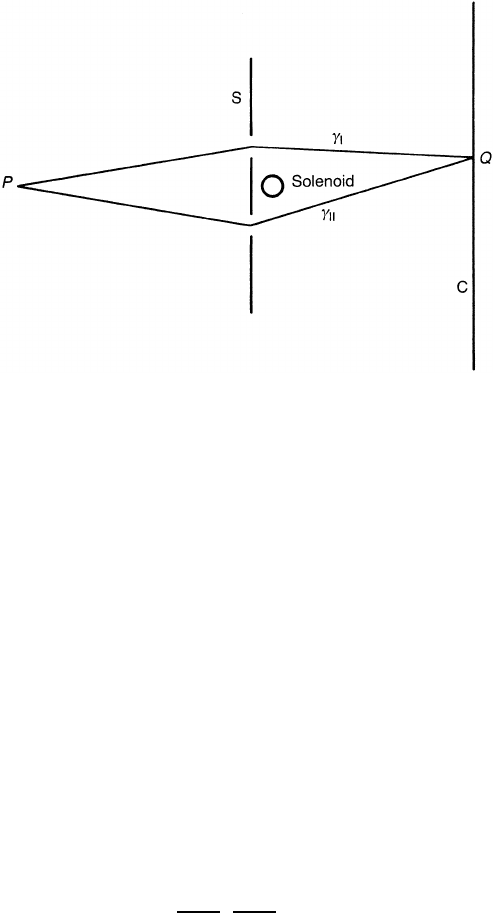
Figure 10.4. The Aharonov–Bohm experiment. B = 0 outside the solenoid.
10.5.3 The Aharonov–Bohm effect
In the elementary study of electromagnetism, the electric and magnetic fields (that
is F
µν
) are of central interest. The vector potential A and the scalar potential
φ = A
0
are considered to be of secondary importance. In quantum mechanics,
however, there are a variety of situations in which F
µν
are not sufficient to
describe the phenomena and the use of A
µ
= ( A, A
0
) is essential. One of these
examples is the Aharonov–Bohm effect.
The Aharonov–Bohm (AB) experiment is schematically described in figure
10.4. A beam of electrons with charge e is incoming from the far left and forms
an interference pattern on the screen C. A solenoid of infinite length is placed in
the middle of the beam. A shield S prevents electrons from penetrating into the
solenoid. Accordingly, the electrons do not feel the magnetic field at all. What
about the gauge field A
µ
?
For simplicity, we make the radius of the solenoid infinitesimally small,
keeping the total flux =
S
B · dS fixed. It is easy to verify that
A(r) =
−
y
2πr
2
,
x
2πr
2
, 0
A
0
= 0 (10.95)
satisfies
(∇×A) · dS = and ∇×A = 0 for r = 0. The vector potential
does not vanish outside the solenoid. Classically, the solenoid cannot have any
influence on electrons since the Lorentz force e(v × B) vanishes on the path of
the beam.
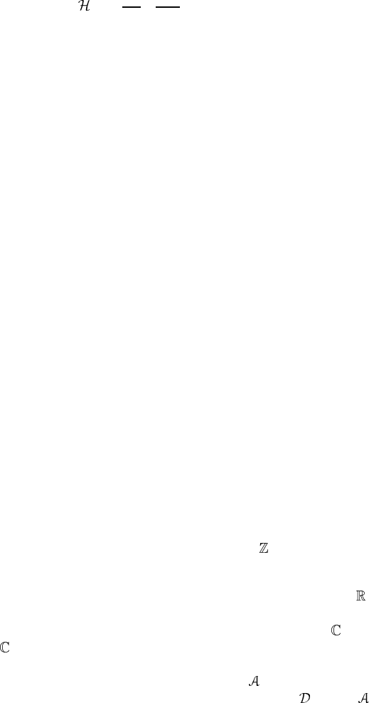
In quantum mechanics, the Hamiltonian H of this system is
=−
1
2m
∂
∂x
µ
− ieA
µ
2
+ V (r) (10.96)
where V (r) represents the effect of the experimental apparatus. Semiclassically,
we can distinguish between the paths γ
I
and γ
II
in figure 10.4. We write the
wavefunction corresponding to γ
I
(γ
II
)asψ
I
(ψ
II
)when A = 0. If A = 0, the
wavefunction is given by the gauge-transformed form,
ψ
A
i
(r) ≡ exp
ie
r
P
A(r
) · dr
ψ
i
(r)(i = I, II) (10.97)
where P is a reference point far from the apparatus. Let us consider a
superposition ψ
A
I
+ ψ
A
II
of wavefunctions ψ
A
I
and ψ
A
II
such that ψ
A
I
(P) =
ψ
A
II
(P). Its amplitude at a point Q on the screen is
ψ
A
I
(Q) + ψ
A
II
(Q) = exp
ie
γ
I
A(r
) ·dr
ψ
I
(Q)
+ exp
ie
γ
II
A(r
) · dr
ψ
II
(Q)
= exp
ie
γ
II
A · dr
exp
ie
'
γ
A · dr
ψ
I
(Q) + ψ
II
(Q)
(10.98)
where γ ≡ γ
I
− γ
II
. It is evident that even though B = 0 at the points in
space through which the electrons travel, the wavefunction depends on the vector
potential A. From Stokes’ theorem, we find that
'
γ
A · dr
=
S
(∇×A) · dS =
S
B · dS = (10.99)
where S is a surface bounded by γ . From this and (10.98), we find the interference
pattern should be the same for two values of the fluxes
a
and
b
if
e(
a
−
b
) = 2πnn∈ . (10.100)
What is the geometry underlying the Aharonov–Bohm effect? Since the
problem is essentially two dimensional, we consider a region M =
2
−{0},
where the solenoid is assumed to be at the origin. The relevant bundles are the
principal bundle P(M, U(1)) and its associated bundle E = P ×
ρ
, where U(1)
acts on
in an obvious way. The bundle E is a complex line bundle over M,
whose section is a wavefunction ψ.
Let us define a Lie-algebra-valued one-form
= iA = i A
µ
dx
µ
.The
covariant derivative associated with this local connection is
= d + ,where
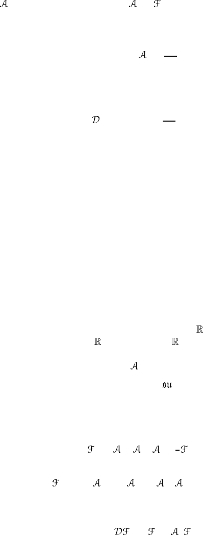
is given by (10.95). Since d = = 0, this connection is locally flat. Let
us consider the unit circle S
1
which encloses the solenoid at the origin. We
parametrize S
1
as e
iθ
(0 ≤ θ ≤ 2π) and write the connection on S
1
as
= i
2π
dθ. (10.101)
This is obtained from (10.95) by putting r = 1. We require that the wavefunction
ψ be parallel transported along S
1
with respect to this local connection, namely
ψ(θ) =
d +i
2π
dθ
ψ(θ) = 0. (10.102)
The solution of (10.102) is easily found to be
ψ(θ) = e
−iθ/2π
. (10.103)
Taking this section ψ amounts to neglecting the velocity of the electrons. The
holonomy : π
−1
(θ = 0) → π
−1
(θ = 2π) = π
−1
(θ = 0) is found to be
: ψ(0) −→ e
−i
ψ(0). (10.104)
In an experiment, a toroidal permalloy (20% Fe and 80% Ni) has been used
to eliminate the edge effects (Tonomura et al 1983). The dimensions of the
permalloy are several microns and it is coated with gold to prevent electrons from
penetrating into the magnetic field.
10.5.4 Yang–Mills theory
Let us consider SU(2) gauge theory defined on
4
. The bundle which describes
this gauge theory is P(
4
, SU(2)).Since
4
is contractible, there is just a single
gauge potential
= A
µ
α
T
α
dx
µ
(10.105)
where T
α
≡ σ
α
/2i generate the algebra (2),
[T
α
, T
β
]=
αβγ
T
γ
.
Thefieldstrengthis
≡ d + ∧ =
1
2
µν
dx
µ
∧ dx
ν
(10.106a)
where
µν
= ∂
µ ν
− ∂
ν µ
+[
µ
,
ν
]=F
µν
α
T
α
(10.106b)
F
µν
α
= ∂
µ
A
να
− ∂
ν
A
µα
+
αβγ
A
µβ
A
νγ
.(10.106c)
The Bianchi identity is
= d +[ , ]=0. (10.107)
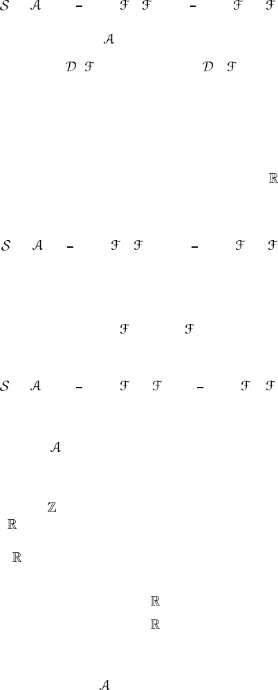
The Yang–Mills action is
YM
[ ]≡−
1
4
M
tr(
µν
µν
) =
1
2
M
tr( ∧∗ ). (10.108)
The variation with respect to
µ
yields
µ
µν
= 0or ∗ = 0. (10.109)
10.5.5 Instantons
A path integral is well defined only on a space with a Euclidean metric. To
evaluate this integral, it is important to find the local minima of the Euclidean
action and compute the quantum fluctuations around them. Let us consider the
SU(2) gauge theory on a four-dimensional Euclidean space
4
. The local minima
of this theory are known as instantons (or pseudoparticles,Belavinet al (1975)),
see section 1.10. It is easy to verify that the Euclidean action is
E
YM
[ ]=
1
4
M
tr(
µν
µν
) =−
1
2
M
tr( ∧∗ ) (10.110)
where the Hodge ∗ is taken with respect to the Euclidean metric. As has been
shown in section 1.10 the field strength corresponding to instantons is self-dual
(anti-self-dual),
µν
=±∗
µν
. (10.111)
The action of a self-dual (anti-self-dual) field configuration is
E
YM
[ ]=−
1
2
M
tr( ∧∗ ) =∓
1
2
M
tr( ∧ ). (10.112)
Let us consider the topological properties of an instanton. We require that
µ
(x ) → g(x )
−1
∂
µ
g(x) as |x |→L (10.113)
for the action to be finite, where L is an arbitrary positive number. Since |x |=L
is the sphere S
3
, (10.113) defines a map g : S
3
→ SU(2) which is classified
by π
3
(SU(2))
∼
=
. How is this reflected upon the transition function? We
compactify
4
by adding the infinity. We suppose the South Pole of S
4
represents
the points at infinity and the North Pole the origin. Under this compactification,
we separate
4
into two pieces and identify them with the southern hemisphere
U
S
and the northern hemisphere U
N
of S
4
as
U
N
={x ∈
4
||x |≤L + ε} (10.114a)
U
S
={x ∈
4
||x |≥L − ε} (10.114b)
see figure 10.5. We assume there is no ‘twist’ of the gauge potential on U
S
and
choose
S
(x ) ≡ 0 x ∈ U
S
. (10.115)
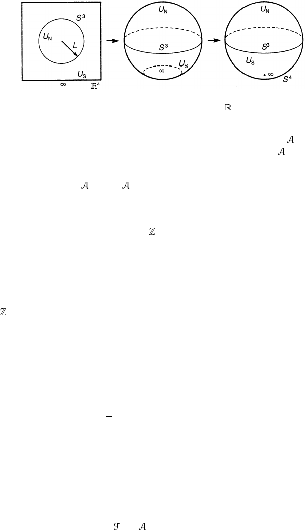
Figure 10.5. One-point compactification of
4
to S
4
.
Then all the topological information about the bundle is contained in
N
(x ) or
the transition function t
NS
(x ) on the ‘equator’ S
3
(=U
N
∩U
S
). Since
S
= 0, we
have, for x ∈ U
N
∩U
S
,
N
= t
−1
NS
S
t
NS
+ t
−1
NS
dt
NS
= t
−1
NS
dt
NS
. (10.116)
Thus, g(x) in (10.113) is identified with the transition function t
NS
(x ) and
classifying the maps g : S
3
→ SU(2) amounts to classifying the transition
functions according to π
3
(SU(2)) = ; see example 9.11.
We now compute the degree of a map g : S
3
→ SU(2) following Coleman
(1979). First note that SU(2) S
3
since
t
4
I
2
+ t
i
σ
i
∈ SU(2) ↔ t
2
+ (t
4
)
2
= 1.
Thus, maps g : S
3
→ SU(2) are classified according to π
3
(SU(2))
∼
=
π
3
(S
3
)
∼
=
. We easily find the following.
(a) The constant map
g
0
: x ∈ S
3
→ e ∈ SU(2) (10.117a)
belongs to the class 0 (i.e. no winding) of π
3
(SU(2)).
(b) The identity map (this is, in fact, the identity map S
3
→ S
3
)
g
1
: x →
1
r
[x
4
I
2
+ x
i
σ
i
], r
2
= x
2
+ (x
4
)
2
(10.117b)
defines the class 1 of π
3
(SU(2)). The explicit form of the gauge potential
corresponding to this homotopy class is given in section 1.10.
(c) The map
g
n
≡ (g
1
)
n
: x → r
−n
[x
4
I
2
+ x
i
σ
i
]
n
(10.117c)
defines the class n of π
3
(SU(2)).
We recall that the strength (charge) of a magnetic monopole is given by the
integral of the field strength
= d over the sphere S
2
. We expect that a similar
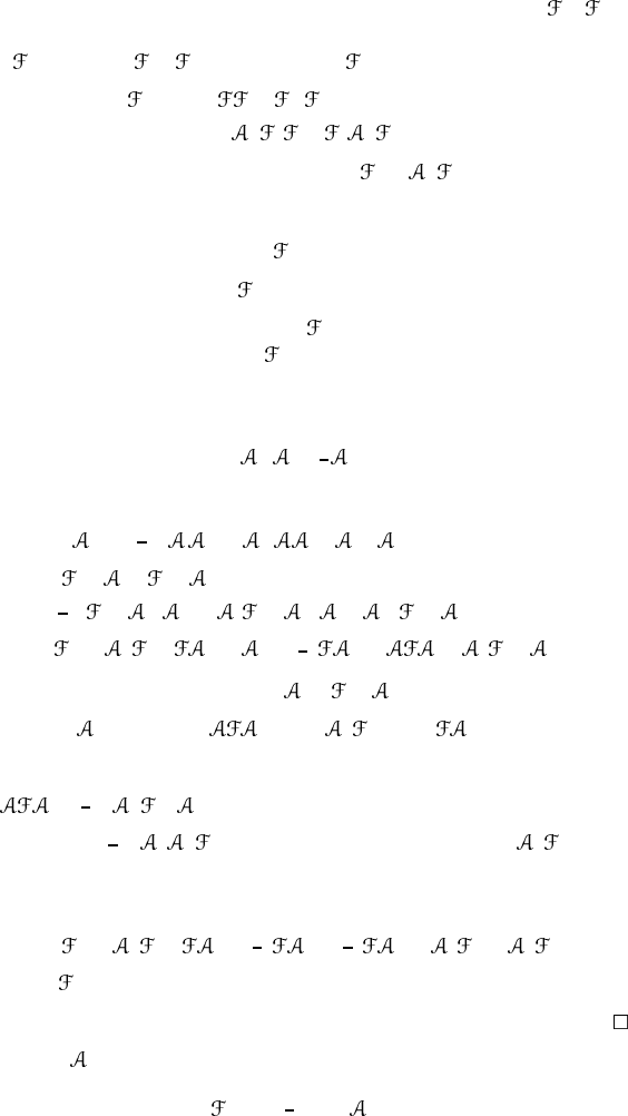
relation exists for the instanton number. Since instantons are defined over S
4
,we
have to find a four-form to be integrated over S
4
. A natural four-form is ∧ .In
the following, we shall omit the exterior product symbol when this does not cause
confusion (
2
stands for ∧ ). Observe that tr
2
is closed,
dtr
2
= tr[d + d ]
= tr{−[
, ] − [ , ]} = 0 (10.118)
where use has been made of the Bianchi identity d
+[ , ]=0. [Remarks:In
the present case, (10.118) seems to be trivial since any four-form on S
4
is closed.
Note, however, that (10.118) remains true even on higher-dimensional manifolds.]
By Poincar´e’s lemma, the closed form tr
2
is locally exact,
tr
2
= dK (10.119)
where K is a local three-form. Thus, tr
2
is an element of the de Rham
cohomology group H
4
(S
4
). Later tr
2
is identified with the second Chern
character and K its Chern–Simons form, see chapter 11.
Lemma 10.3. The three-form K in (10.119) is given by
K = tr[
d +
2
3
3
]. (10.120)
Proof. A straightforward computation yields
dK = tr[(d
)
2
+
2
3
(d
2
− d +
2
d )]
= tr[(
−
2
)( −
2
)
+
2
3
{( −
2
)
2
− ( −
2
) +
2
( −
2
)}]
= tr[
2
−
2
−
2
+
4
+
2
3
(
2
− +
2
−
4
)]
where use has been made of the identity d
= −
2
. Now we note that
tr
4
= 0tr =−tr
2
=−tr
2
.
For example, we have
tr
=
1
2
tr
κ λµ ν
dx
κ
∧ dx
λ
∧ dx
µ
∧ dx
ν
=−
1
2
tr
ν κ λµ
dx
ν
∧ dx
κ
∧ dx
λ
∧ dx
µ
=−tr
2
where the cyclicity of the trace and the anti-commutativity of dx
µ
have been used.
Then dK becomes
dK = tr[
2
−
2
−
2
+
2
3
{
2
+
1
2
(
2
+
2
) +
2
}]
= tr
2
as has been claimed.
Lemma 10.4. Let be the gauge potential of an instanton. Then it follows that
S
4
tr
2
=−
1
3
S
3
tr
3
. (10.121)
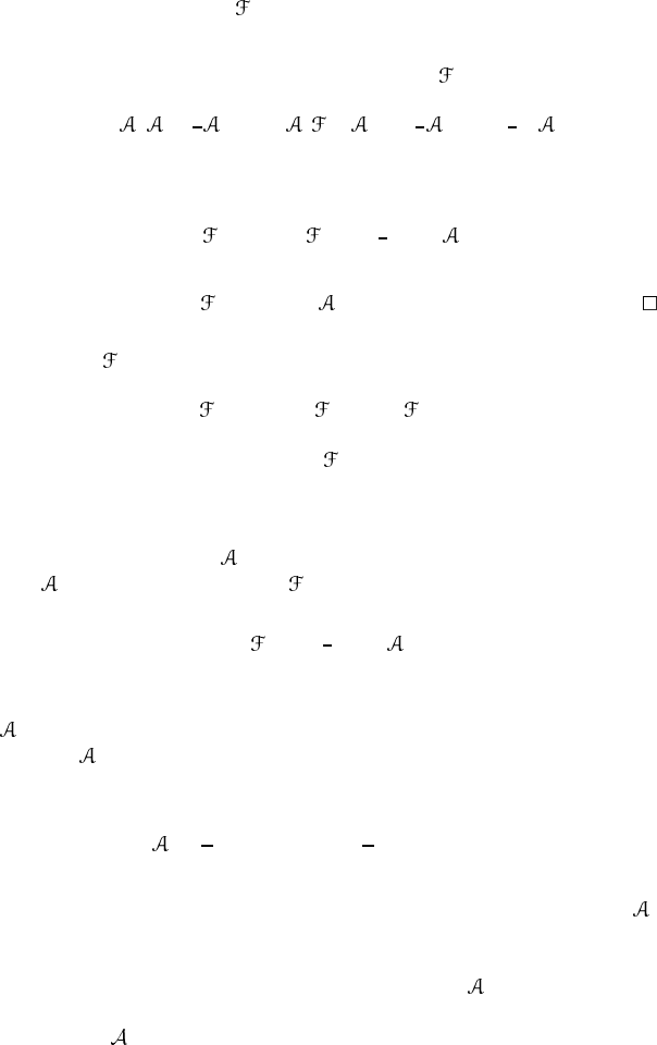
Proof. From Stokes’ theorem, we find that
U
N
tr
2
=
U
N
dK =
S
3
K
where U
N
is defined by (10.114) and S
3
= ∂U
N
.Since = 0onS
3
, we obtain
K = tr[
d +
2
3
3
]=tr[ ( −
2
) +
2
3
3
]=−
1
3
tr
3
on S
3
, from which we find that
U
N
tr
2
=
S
4
tr
2
=−
1
3
S
3
tr
3
wherewehaveadded
U
S
tr
2
= 0since
S
≡ 0.
Note that tr
2
is invariant under the gauge transformation,
tr
2
→ tr[g
−1 2
g]=tr
2
.
Thus, it is reasonable to assume that tr
2
indeed contains a certain amount
of topological information about the bundle, which is independent of particular
connections. Let us consider the gauge fields (10.117a−c) given before. We find:
(a) For g
0
(x ) ≡ e,wehave = 0onS
3
. Since the bundle is trivial we may
take
= 0 throughout S
4
.Then = 0, hence
S
4
tr
2
=−
1
3
S
3
tr
3
= 0. (10.122)
Note that this relation is true for any gauge potential which is obtained from
= 0 by smooth gauge transformations, that is for any gauge potential of
the form
(x ) = g(x)
−1
dg (x), x ∈ S
4
.
(b) Next consider a gauge potential whose value on S
3
is given by (10.117b) as
=
1
r
(x
4
− ix
k
σ
k
) d
1
r
(x
4
+ ix
l
σ
l
)
. (10.123)
A considerable simplification is achieved if we note that the integrand tr
3
should not depend on the point on S
3
at which it is evaluated since g
1
maps
S
3
onto SU(2)
∼
=
S
3
in a uniform way. So we may evaluate it at the North
Pole (x
4
= 1, x = 0) of the unit sphere. We then find = iσ
k
dx
k
and
tr
3
= i
3
tr[σ
i
σ
j
σ
k
]dx
i
∧ dx
j
∧ dx
k
= 2ε
ijk
dx
i
∧ dx
j
∧ dx
k
= 12 dx
1
∧ dx
2
∧ dx
3
. (10.124)
Next we note that (x
1
, x
2
, x
3
) is a good coordinate system on each
hemisphere of S
3
and ω ≡ dx
1
∧ dx
2
∧ dx
3
is a volume element at the
North Pole. We find
S
3
tr
3
= 12
S
3
ω = 12(2π
2
) = 24π
2
where 2π
2
is the area of the unit sphere S
3
. We finally obtain
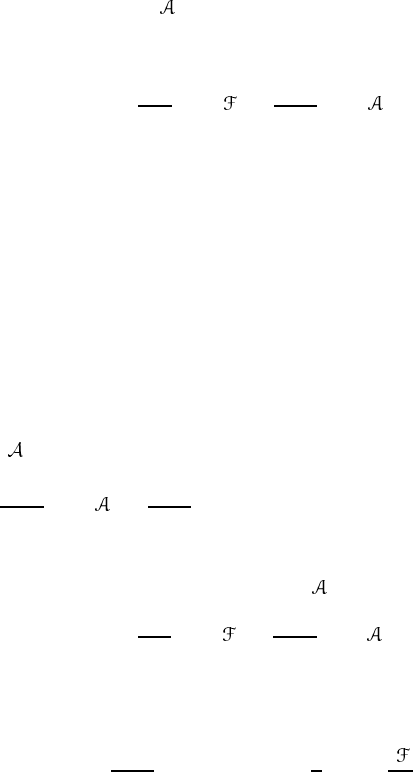
−
1
8π
2
S
4
tr
2
=
1
24π
2
S
3
tr
3
= 1. (10.125)
(c) Next we consider the map g
n
: S
3
→ SU(2) given by (10.117c). We
show that g
2
= g
1
g
1
has a winding number 2. We divide S
3
into the
northern hemisphere U
(3)
N
and the southern hemisphere U
(3)
S
. Given a map
g
1
: S
3
→ SU(2), it is always possible to transform g
1
smoothly to g
1N
which has the winding number one and g
1N
(x ) = e for x ∈ U
(3)
S
. All the
variation takes place on U
(3)
N
. Similarly, g
1
may be deformed to g
1S
with the
same winding number and g
1S
(x ) = e for x ∈ U
(3)
N
. Under this deformation,
g
2
becomes
g
2
(x ) → g
2
(x ) =
g
1N
(x ) x ∈ U
(3)
N
g
1S
(x ) x ∈ U
(3)
S
.
For
(x ) = g
2
(x )
−1
dg
2
(x )(x ∈ S
3
),wehave
1
24π
3
S
3
tr
3
=
1
24π
2
U
(3)
N
tr(g
−1
1N
dg
1N
)
3
+
U
(3)
S
tr(g
−1
1S
dg
1S
)
3
= 1 + 1 = 2. (10.126)
Repeating the same procedure we find for
(x ) = g
−1
n
dg
n
that
−
1
8π
2
S
4
tr
2
=
1
24π
2
S
3
tr
3
= n. (10.127)
Collecting these results we establish the following theorem.
Theorem 10.7. The degree of mapping g : S
3
→ SU(2) is given by
n =
1
24π
2
S
3
tr(g
−1
dg)
3
=
1
2
S
4
tr
i
2π
2
. (10.128)
10.6 Berry’s phase
In quantum mechanics, we define a wavefunction up to the phase. In most
cases, the phase is neglected as an irrelevant factor. Berry (1984) pointed out
that if the system undergoes an adiabatic change, the phase may have observable
consequences.

10.6.1 Derivation of Berry’s phase
Let H (R) be a Hamiltonian which depends on some parameters collectively
written as R. Suppose R changes adiabatically as a function of time, R = R(t).
The Schr¨odinger equation is
H (R(t))|ψ(t)=i
d
dt
|ψ(t). (10.129)
We assume the system at t = 0isinthenth eigenstate, |ψ(0)=|n, R(0) where
H (R(0))|n, R(0)=E
n
(R(0))|n, R(0). (10.130)
What about the state |ψ(t) at later time t > 0? We assume the system is always
in the nth state, i.e. no level crossing takes place (adiabatic assumption).
Exercise 10.13. A naive guess of |ψ(t) is
|ψ(t)=exp
− i
t
0
dsE
n
(R(s))
|n, R(t) (10.131)
where the normalized state |n, R(t) satisfies
H (R(t))|n, R(t)=E
n
(R(t))|n, R(t). (10.132)
Show that (10.131) is not a solution of (10.129).
Since (10.131) does not satisfy the Schr¨odinger equation, we have to try
other possibilities. Let us introduce an extra-phase η
n
(t) in the wavefunction:
|ψ(t)=exp
iη(t) − i
t
0
E
n
(R(s)) ds
|n, R(t). (10.133)
Inserting (10.133) into the Schr¨odinger equation (10.129), we find
H (R(t))|ψ(t)=E
n
(R(t))|ψ(t)
for the LHS (see (10.132)) and
i
d
dt
|ψ(t)=
−
dη
n
(t)
dt
+ E
n
(R(t))
|ψ(t)
+ exp
iη
n
(t) − i
E
n
(R(s)) ds
i
d
dt
|n, R(t)
for the RHS. Equating these, it is found that η
n
(t) satisifes
dη
n
(t)
dt
= in, R(t)|
d
dt
|n, R(t). (10.134)

By integrating (10.134), we obtain
η
n
(t) = i
t
0
n, R(s)|
d
ds
|n, R(s)ds
= i
R(t)
R(0)
n, R|∇
R
|n, RdR (10.135)
where ∇
R
stands for the gradient in R-space. Note that η
n
(t) is real since
2Ren, R(s)|
d
ds
|n, R(s)
=n, R(s)|
d
ds
|n, R(s)+
d
ds
n, R(s)|
|n, R(s)
=
d
ds
n, R(s)|n, R(s)=0.
Suppose the system executes a closed loop in R-space; R(0) = R(T ) for some
T > 0. We then have
η
n
(T ) = i
T
0
n, R(s)|
d
ds
|n, R(s)ds
= i
R(T )
R(0)
n, R|∇
R
|n, RdR. (10.136)
Since R(T ) = R(0), the last expression seems to vanish. However, the integrand
is not necessarily a total derivative and η
n
(T ) may fail to vanish. The phase η
n
(T )
is called Berry’s phase (Berry 1984).
It was Simon (1983) who first recognized the deep geometrical meaning
underlying Berry’s phase. He observed that the origin of Berry’s phase is
attributed to the holonomy in the parameter space. We shall work out this point
of view following Berry (1984), Simon (1983), Aitchison (1987) and Zumino
(1987).
10.6.2 Berry’s phase, Berry’s connection and Berry’s curvature
Let M be a manifold describing the parameter space and let R = (R
1
,...,R
k
)
be the local coordinate. At each point R of M, we consider the normalized nth
eigenstate of the Hamiltonian H (R). Since a quantum state |n; R cannot be
distinguished from e
iφ
|n; R, a physical state is expressed by an equivalence class
[|R] ≡ {g|R|g ∈ U(1)} (10.137)
where we omit the index n since we are interested only in the nth eigenvector
(figure 10.6). At each point R of M, we have a U(l) degree of freedom and we
have a U(l) bundle P(M, U(1)) over the parameter space M. The projection is
given by π(g|R) = R.
