Moran M.J., Shapiro H.N. Fundamentals of Engineering Thermodynamics
Подождите немного. Документ загружается.

6.10 Rate Balances for Control Volumes at Steady State 313
Determining Entropy Production in Heat Pump Components
c c c c EXAMPLE 6.8 c
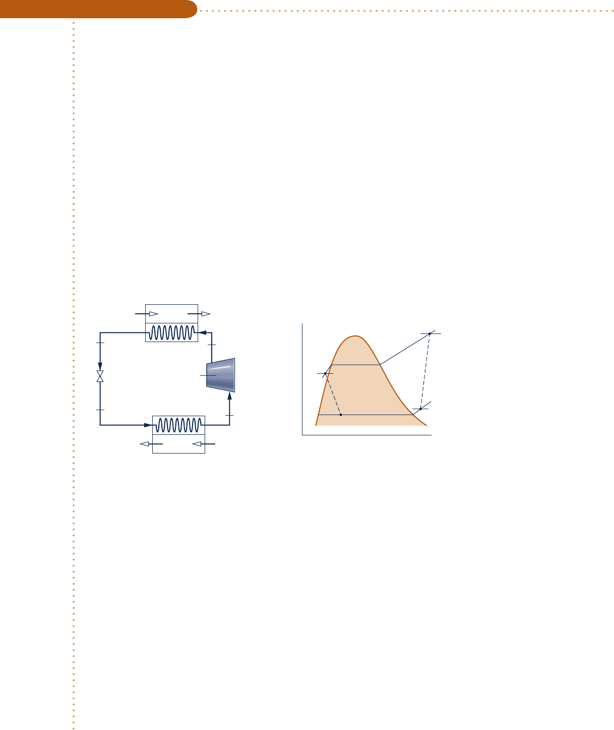
Components of a heat pump for supplying heated air to a dwelling are shown in the schematic below. At steady
state, Refrigerant 22 enters the compressor at 258C, 3.5 bar and is compressed adiabatically to 758C, 14 bar.
From the compressor, the refrigerant passes through the condenser, where it condenses to liquid at 288C, 14 bar.
The refrigerant then expands through a throttling valve to 3.5 bar. The states of the refrigerant are shown on
the accompanying T–s diagram. Return air from the dwelling enters the condenser at 208C, 1 bar with a volu-
metric flow rate of 0.42 m
3
/s and exits at 508C with a negligible change in pressure. Using the ideal gas model
for the air and neglecting kinetic and potential energy effects, (a) determine the rates of entropy production, in
kW/K, for control volumes enclosing the condenser, compressor, and expansion valve, respectively. (b) Discuss
the sources of irreversibility in the components considered in part (a).
SOLUTION
Known:
Refrigerant 22 is compressed adiabatically, condensed by heat transfer to air passing through a heat
exchanger, and then expanded through a throttling valve. Steady-state operating data are known.
Find: Determine the entropy production rates for control volumes enclosing the condenser, compressor, and
expansion valve, respectively, and discuss the sources of irreversibility in these components.
Schematic and Given Data:
Fig. E6.8
T
s
3
4
1
2
75°C
–5°C
28°C
14 bar
3.5 bar
56
Expansion
valve
3
4
p
4
= 3.5 bar
p
3
= 14 bar
T
3
= 28°C
Condenser
Indoor return air
T
5
= 20°C
p
5
= 1 bar
(AV)
5
= 0.42 m
3
/s
1
2
T
1
= –5°C
p
1
= 3.5 bar
p
2
= 14 bar
T
2
= 75°C
Supply air
T
6
= 50°C
p
6
= 1 bar
Evaporator
Outdoor air
Compressor
Engineering Model:
1.
Each component is analyzed as a control volume at steady state.
2. The compressor operates adiabatically, and the expansion across the valve is a throttling process.
3. For the control volume enclosing the condenser, W
#
cv
5 0 and Q
#
cv
5 0.
4. Kinetic and potential energy effects can be neglected.
5. The air is modeled as an ideal gas with constant c
p
5 1.005 kJ/kg
?
K.
Analysis:
(a)
Let us begin by obtaining property data at each of the principal refrigerant states located on the accompany-
ing schematic and T–s diagram. At the inlet to the compressor, the refrigerant is a superheated vapor at 258C,
3.5 bar, so from Table A-9, s
1
5 0.9572 kJ/kg
?
K. Similarly, at state 2, the refrigerant is a superheated vapor at
758C, 14 bar, so interpolating in Table A-9 gives s
2
5 0.98225 kJ/kg
?
K and h
2
5 294.17 kJ/kg.
➊
c06UsingEntropy.indd Page 313 5/28/10 1:22:06 PM user-s146c06UsingEntropy.indd Page 313 5/28/10 1:22:06 PM user-s146 /Users/user-s146/Desktop/Merry_X-Mas/New/Users/user-s146/Desktop/Merry_X-Mas/New

314 Chapter 6 Using Entropy
State 3 is compressed liquid at 288C, 14 bar. From Table A-7, s
3
<
s
f
(288C) 5 0.2936 kJ/kg
?
K and h
3
<
h
f
(288C) 5
79.05 kJ/kg. The expansion through the valve is a throttling process, so h
3
5 h
4
. Using data from Table A-8, the
quality at state 4 is
x
4
5
1h
4
2 h
f4
2
1h
fg
2
4
5
179.05 2 33.09
2
1212.912
5 0.216
and the specific entropy is
s
4
5 s
f4
1 x
4
1
s
g
4
2 s
f4
2
5 0.1328 1 0.216
1
0.9431 2 0.1328
2
5 0.3078 kJ
/
kg ? K
Condenser
Consider the control volume enclosing the condenser. With assumptions 1 and 3, the entropy rate balance reduces to
0 5 m
#
ref
1s
2
2 s
3
21 m
#
air
1s
5
2 s
6
21 s
#
cond
To evaluate s
#
cond
requires the two mass flow rates, m
#
air
and m
#
ref
, and the change in specific entropy for the air.
These are obtained next.
Evaluating the mass flow rate of air using the ideal gas model and the known volumetric flow rate
m
#
air
5
1AV2
5
y
5
5 1AV2
5
p
5
RT
5
5 a0.42
m
3
s
b
11 bar
2
a
8.31
4
28.97
kJ
kg ? K
b1293 K2
`
10
5
N
/
m
2
1 bar
``
1 kJ
10
3
N ? m
`5 0.5 kg
/
s
The refrigerant mass flow rate is determined using an energy balance for the control volume enclosing the con-
denser together with assumptions 1, 3, and 4 to obtain
m
#
ref
5
m
#
air
1h
6
2 h
5
2
1h
2
2 h
3
2
With assumption 5, h
6
2 h
5
5 c
p
(T
6
2 T
5
). Inserting values
m
#
ref
5
a0.
5
kg
s
ba1.
005
kJ
kg ? K
b1323 2 2932K
1294.17 2 79.052 kJ
/
kg
5 0.07 kg
/
s
Using Eq. 6.22, the change in specific entropy of the air is
s
6
2 s
5
5 c
p
ln
T
6
T
5
2 R ln
p
6
p
5
5 a1.005
kJ
kg ? K
b ln a
323
293
b2 R ln a
1.0
1.0
b
0
5 0.098 kJ
/
kg ? K
Finally, solving the entropy balance for s
#
cond
and inserting values
s
#
cond
5 m
#
ref
1s
3
2 s
2
21 m
#
air
1s
6
2 s
5
2
5 ca0.07
kg
s
b
10.2936 2 0.982252
kJ
kg ? K
1 10.5210.0982d`
1 kW
1 kJ
/
s
`
5 7.95 3 10
24
kW
K
Compressor
For the control volume enclosing the compressor, the entropy rate balance reduces with assumptions 1 and
3 to
0 5 m
#
ref
1
s
1
2 s
2
2
1 s
#
comp
➋
c06UsingEntropy.indd Page 314 5/26/10 5:20:34 PM user-s146c06UsingEntropy.indd Page 314 5/26/10 5:20:34 PM user-s146 /Users/user-s146/Desktop/Merry_X-Mas/New/Users/user-s146/Desktop/Merry_X-Mas/New

or
s
#
comp
5 m
#
ref
1
s
2
2 s
1
2
5 a0.07
kg
s
b10.98225 2 0.95722a
k
J
kg ? K
b`
1 kW
1 kJ
/
s
`
5
17.5
3
10
24
kW
/
K
Valve
Finally, for the control volume enclosing the throttling valve, the entropy rate balance reduces to
0 5 m
#
ref
1
s
3
2 s
4
2
1 s
#
valve
Solving for s
#
valve
and inserting values
s
#
valve
5 m
#
ref
1s
4
2 s
3
25 a0.07
k
g
s
b10.3078 2 0.29362a
k
J
kg ? K
b`
1 kW
1 kJ
/
s
`
5
9.9
4 3 1
0
24
k
W
/
K
(b) The following table summarizes, in rank order, the calculated entropy production rates:
Component s
#
cv
(kW/K)
compressor 17.5 3 10
24
valve 9.94 3 10
24
condenser 7.95 3 10
24
Entropy production in the compressor is due to fluid friction, mechanical friction of the moving parts, and inter-
nal heat transfer. For the valve, the irreversibility is primarily due to fluid friction accompanying the expansion
across the valve. The principal source of irreversibility in the condenser is the temperature difference between
the air and refrigerant streams. In this example, there are no pressure drops for either stream passing through
the condenser, but slight pressure drops due to fluid friction would normally contribute to the irreversibility of
condensers. The evaporator shown in Fig. E6.8 has not been analyzed.
➊ Due to the relatively small temperature change of the air, the specific heat c
p
can be taken as constant at the average of the inlet and exit air temperatures.
➋ Temperatures in K are used to evaluate m
#
ref
, but since a temperature differ-
ence is involved the same result would be obtained if temperatures in °C were
used. Temperatures in K, and not °C, are required when a temperature ratio
is involved, as in Eq. 6.22 used to evaluate s
6
2 s
5
.
➌ By focusing attention on reducing irreversibilities at the sites with the highest
entropy production rates, thermodynamic improvements may be possible. How-
ever, costs and other constraints must be considered, and can be overriding.
Ability to…
❑
apply the control volume
mass, energy and entropy
rate balances.
❑
develop an engineering model.
❑
retrieve property data for
Refrigerant 22.
❑
apply the ideal gas model
with constant c
p
.
✓
Skills Developed
If the compressor operated adiabatically and without internal
irreversibilities, determine the temperature of the refrigerant at the com-
pressor exit, in °C, keeping the compressor inlet state and exit pressure
the same. Ans. 65°C.
6.11 Isentropic Processes
The term isentropic means constant entropy. Isentropic processes are encountered in
many subsequent discussions. The object of the present section is to show how prop-
erties are related at any two states of a process in which there is no change in specific
entropy.
➌
6.11 Isentropic Processes 315
c06UsingEntropy.indd Page 315 5/26/10 2:41:20 PM user-s146c06UsingEntropy.indd Page 315 5/26/10 2:41:20 PM user-s146 /Users/user-s146/Desktop/Merry_X-Mas/New/Users/user-s146/Desktop/Merry_X-Mas/New

316 Chapter 6 Using Entropy
6.11.1
General Considerations
The properties at states having the same specific entropy can be related using the
graphical and tabular property data discussed in Sec. 6.2. For example, as illustrated
by Fig. 6.8, temperature–entropy and enthalpy–entropy diagrams are particularly con-
venient for determining properties at states having the same value of specific entropy.
All states on a vertical line passing through a given state have the same entropy. If
state 1 on Fig. 6.8 is fixed by pressure p
1
and temperature T
1
, states 2 and 3 are read-
ily located once one additional property, such as pressure or temperature, is specified.
The values of several other properties at states 2 and 3 can then be read directly from
the figures.
Tabular data also can be used to relate two states having the same specific entropy.
For the case shown in Fig. 6.8, the specific entropy at state 1 could be determined
from the superheated vapor table. Then, with s
2
5 s
1
and one other property value,
such as p
2
or T
2
, state 2 could be located in the superheated vapor table. The values
of the properties y, u, and h at state 2 can then be read from the table. (An illustra-
tion of this procedure is given in Sec. 6.2.1.) Note that state 3 falls in the two-phase
liquid–vapor regions of Fig. 6.8. Since s
3
5 s
1
, the quality at state 3 could be deter-
mined using Eq. 6.4. With the quality known, other properties such as y, u, and h
could then be evaluated. Computer retrieval of entropy data provides an alternative
to tabular data.
6.11.2
Using the Ideal Gas Model
Figure 6.9 shows two states of an ideal gas having the same value of specific
entropy. Let us consider relations among pressure, specific volume, and tempera-
ture at these states, first using the ideal gas tables and then assuming specific heats
are constant.
Ideal Gas Tables
For two states having the same specific entropy, Eq. 6.20a reduces to
0 5 s81T
2
22 s81T
1
22 R ln
p
2
p
1
(6.40a)
Equation 6.40a involves four property values: p
1
, T
1
, p
2
, and T
2
. If any three are
known, the fourth can be determined. If, for example, the temperature at state 1 and
T
1
2
3
p
1
T
1
p
2
p
3
T
2
T
3
h
ss
1
2
3
p
1
T
1
p
2
p
3
T
2
T
3
Fig. 6.8 T–s and h–s diagrams showing states having the same value of specific entropy.
T
s
2
1
v
2
v
1
p
1
T
1
p
2
T
2
Fig. 6.9 Two states of an
ideal gas where s
2
= s
1
.
c06UsingEntropy.indd Page 316 5/26/10 2:41:21 PM user-s146c06UsingEntropy.indd Page 316 5/26/10 2:41:21 PM user-s146 /Users/user-s146/Desktop/Merry_X-Mas/New/Users/user-s146/Desktop/Merry_X-Mas/New

the pressure ratio p
2
/p
1
are known, the temperature at state 2 can be determined
from
s81T
2
25 s81T
1
21 R ln
p
2
p
1
(6.40b)
Since T
1
is known, s8(T
1
) would be obtained from the appropriate table, the value of
s8(T
2
) would be calculated, and temperature T
2
would then be determined by inter-
polation. If p
1
, T
1
, and T
2
are specified and the pressure at state 2 is the unknown,
Eq. 6.40a would be solved to obtain
p
2
5 p
1
exp
c
s81T
2
22 s81T
1
2
R
d
(6.40c)
Equations 6.40 can be used when s8 (or
s8
) data are known, as for the gases of Tables
A-22 and A-23.
AIR.
For the special case of air modeled as an ideal gas, Eq. 6.40c provides the
basis for an alternative tabular approach for relating the temperatures and pres-
sures at two states having the same specific entropy. To introduce this, rewrite the
equation as
p
2
p
1
5
exp
3
s8
1
T
2
2
/
R
4
exp
3
s8
1
T
1
2
/
R
4
The quantity exp[s8(T)/R] appearing in this expression is solely a function of tem-
perature, and is given the symbol p
r
(T). A tabulation of p
r
versus temperature for
air is provided in Tables A-22.
1
In terms of the function p
r
, the last equation
becomes
p
2
p
1
5
p
r2
p
r1
1s
1
5 s
2
, air only2
(6.41)
where p
r1
5 p
r
(T
1
) and p
r2
5 p
r
(T
2
). The function p
r
is sometimes called the relative
pressure. Observe that p
r
is not truly a pressure, so the name relative pressure has no
physical significance. Also, be careful not to confuse p
r
with the reduced pressure of
the compressibility diagram.
A relation between specific volumes and temperatures for two states of air having
the same specific entropy can also be developed. With the ideal gas equation of state,
y 5 RT/p, the ratio of the specific volumes is
y
2
y
1
5
a
RT
2
p
2
ba
p
1
RT
1
b
Then, since the two states have the same specific entropy, Eq. 6.41 can be introduced
to give
y
2
y
1
5 c
RT
2
p
r
1
T
2
2
dc
p
r
1T
1
2
RT
1
d
The ratio RT/p
r
(T) appearing on the right side of the last equation is solely a func-
tion of temperature, and is given the symbol y
r
(T). Values of y
r
for air are tabulated
1
The values of p
r
determined with this definition are inconveniently large, so they are divided by a scale factor
before tabulating to give a convenient range of numbers.
TAKE NOTE...
When applying the software
IT to relate two states of
an ideal gas having the
same value of specific
entropy, IT returns specific
entropy directly and does
not employ the special
functions s°, p
r
,
and v
r
.
6.11 Isentropic Processes 317
c06UsingEntropy.indd Page 317 5/26/10 3:28:42 PM user-s146 c06UsingEntropy.indd Page 317 5/26/10 3:28:42 PM user-s146 /Users/user-s146/Desktop/Merry_X-Mas/New/Users/user-s146/Desktop/Merry_X-Mas/New

318 Chapter 6 Using Entropy
versus temperature in Tables A-22. In terms of the function y
r
, the last equation
becomes
y
2
y
1
5
y
r2
y
r1
1s
1
5 s
2
, air only2
(6.42)
where y
r1
5 y
r
(T
1
) and y
r2
5 y
r
(T
2
). The function y
r
is sometimes called the relative
volume. Despite the name given to it, y
r
(T) is not truly a volume. Also, be careful
not to confuse it with the pseudoreduced specific volume of the compressibility
diagram.
Assuming Constant Specific Heats
Let us consider next how properties are related for isentropic processes of an ideal
gas when the specific heats are constants. For any such case, Eqs. 6.21 and 6.22 reduce
to the equations
0 5 c
p
ln
T
2
T
1
2 R ln
p
2
p
1
0 5 c
y
ln
T
2
T
1
1 R ln
y
2
y
1
Introducing the ideal gas relations
c
p
5
kR
k 2 1
,
c
y
5
R
k 2 1
(3.47)
where k is the specific heat ratio and R is the gas constant, these equations can be
solved, respectively, to give
T
2
T
1
5 a
p
2
p
1
b
1
k21
2
/
k
1s
1
5 s
2
, constant k2
(6.43)
T
2
T
1
5 a
y
1
y
2
b
k21
1s
1
5 s
2
, constant k2
(6.44)
The following relation can be obtained by eliminating the temperature ratio from
Eqs. 6.43 and 6.44:
p
2
p
1
5
a
y
1
y
2
b
k
1s
1
5 s
2
, constant k2
(6.45)
Previously, we have identified an internally reversible process described by py
n
5
constant, where n is a constant, as a polytropic process. From the form of Eq. 6.45, it
can be concluded that the polytropic process py
k
5 constant of an ideal gas with
constant specific heat ratio k is an isentropic process. We observed in Sec. 3.15 that
a polytropic process of an ideal gas for which n 5 1 is an isothermal (constant-
temperature) process. For any fluid, n 5 0 corresponds to an isobaric (constant-pressure)
process and n 5
6q
corresponds to an isometric (constant-volume) process. Poly-
tropic processes corresponding to these values of n are shown in Fig. 6.10 on p–y and
T–s diagrams.
6.11.3
Illustrations: Isentropic Processes of Air
Means for evaluating data for isentropic processes of air modeled as an ideal gas are
illustrated in the next two examples. In Example 6.9, we consider three alternative
methods.
c06UsingEntropy.indd Page 318 5/26/10 3:28:44 PM user-s146 c06UsingEntropy.indd Page 318 5/26/10 3:28:44 PM user-s146 /Users/user-s146/Desktop/Merry_X-Mas/New/Users/user-s146/Desktop/Merry_X-Mas/New

Analyzing an Isentropic Process of Air
c c c c EXAMPLE 6.9 c
Air undergoes an isentropic process from p
1
5 1 atm, T
1
5 5408R to a final state where the temperature is
T
2
5 11608R. Employing the ideal gas model, determine the final pressure p
2
, in atm. Solve using (a) p
r
data
from Table A-22E, (b) Interactive Thermodynamics: IT, and (c) a constant specific heat ratio k evaluated at the
mean temperature, 8508R, from Table A-20E.
SOLUTION
Known:
Air undergoes an isentropic process from a state where pressure and temperature are known to a state
where the temperature is specified.
Find: Determine the final pressure using (a) p
r
data, (b) IT, and (c) a constant value for the specific heat ratio k.
Schematic and Given Data:
Engineering Model:
1.
A quantity of air as the system undergoes an isentropic process.
2. The air can be modeled as an ideal gas.
3. In part (c) the specific heat ratio is constant.
Analysis:
(a)
The pressures and temperatures at two states of an ideal gas having the same specific entropy are related by
Eq. 6.41
p
2
p
1
5
p
r2
p
r1
Solving
p
2
5 p
1
p
r2
p
r1
2
1
p
2
= ?
T
2
= 1160°R
p
1
= 1 atm
T
1
= 540°R
T
s
Fig. E6.9
p
v
s
=
c
o
n
s
t
a
n
t
T
=
c
o
n
s
t
a
n
t
n = –1
n = 0
n = 1
n = k
n = ± ∞
n = ±
∞
T
s
v
=
c
o
n
s
t
a
n
t
p
=
c
o
n
s
t
a
n
t
n = –1
n = 0
n = 1
n = k
Fig. 6.10 Polytropic processes on p–y and T–s diagrams.
6.11 Isentropic Processes 319
c06UsingEntropy.indd Page 319 5/26/10 3:28:45 PM user-s146 c06UsingEntropy.indd Page 319 5/26/10 3:28:45 PM user-s146 /Users/user-s146/Desktop/Merry_X-Mas/New/Users/user-s146/Desktop/Merry_X-Mas/New

320 Chapter 6 Using Entropy
Another illustration of an isentropic process of an ideal gas is provided in Exam-
ple 6.10 dealing with air leaking from a tank.
Considering Air Leaking from a Tank
c c c c EXAMPLE 6.10 c
A rigid, well-insulated tank is filled initially with 5 kg of air at a pressure of 5 bar and a temperature of 500 K.
A leak develops, and air slowly escapes until the pressure of the air remaining in the tank is 1 bar. Employing
the ideal gas model, determine the amount of mass remaining in the tank and its temperature.
SOLUTION
Known:
A leak develops in a rigid, insulated tank initially containing air at a known state. Air slowly escapes
until the pressure in the tank is reduced to a specified value.
Find: Determine the amount of mass remaining in the tank and its temperature.
With p
r
values from Table A-22E
p 5 11 atm2
21.18
1.3860
5 15.28 at
m
(b) The IT solution follows:
T1 5 540 // °R
p1 5 1 // atm
T2 5 1160 // °R
s_TP(“Air”, T1,p1) 5 s_TP(“Air”,T2,p2)
// Result: p2 5 15.28 atm
(c) When the specific heat ratio k is assumed constant, the temperatures and pressures at two states of an ideal
gas having the same specific entropy are related by Eq. 6.43. Thus
p
2
5 p
1
a
T
2
T
1
b
k
/
1
k21
2
From Table A-20E at the mean temperature, 3908F (8508R), k 5 1.39. Inserting values into the above
expression
p
2
5 11 atm2
a
1160
540
b
1.39
/
0.39
5 15.26 at
m
➊ IT returns a value for p
2
even though it is an implicit variable in the specific
entropy function. Also note that IT returns values for specific entropy directly
and does not employ special functions such as s8, p
r
, and y
r
.
➋ The close agreement between the answer obtained in part (c) and that of
parts (a), (b) can be attributed to the use of an appropriate value for the
specific heat ratio k.
Determine the final pressure, in atm, using a constant specific
heat ratio k evaluated at T
1
5 5408R. Expressed as a percent, how much does
this pressure value differ from that of part (c)? Ans. 14.53 atm, 25%.
Ability to…
❑
analyze an isentropic process
using Table A-22E data,
❑
Interactive Thermodynamics,
and
❑
a constant specific heat
ratio k.
✓
Skills Developed
➊
➋
c06UsingEntropy.indd Page 320 5/26/10 3:28:49 PM user-s146 c06UsingEntropy.indd Page 320 5/26/10 3:28:49 PM user-s146 /Users/user-s146/Desktop/Merry_X-Mas/New/Users/user-s146/Desktop/Merry_X-Mas/New

6.11 Isentropic Processes 321
Analysis: With the ideal gas equation of state, the mass initially in the tank that remains in the tank at the end
of the process is
m
2
5
p
2
V
1
R
/
M
2
T
2
where p
2
and T
2
are the final pressure and temperature, respectively. Similarly, the initial amount of mass within
the tank, m
1
is
m
1
5
p
1
V
1
R
/
M
2
T
1
where p
1
and T
1
are the initial pressure and temperature, respectively. Eliminating volume between these two
expressions, the mass of the system is
m
2
5
a
p
2
p
1
ba
T
1
T
2
b
m
1
Except for the final temperature of the air remaining in the tank, T
2
, all required values are known. The remain-
der of the solution mainly concerns the evaluation of T
2
.
For the closed system under consideration, there are no significant irreversibilities (assumption 3), and no
heat transfer occurs (assumption 2). Accordingly, the entropy balance reduces to
¢S 5
#
2
1
a
d
Q
T
b
b
0
1 s
0
5 0
Since the system mass remains constant, ¢S 5 m
2
¢s, so
¢s 5 0
That is, the initial and final states of the system have the same value of specific entropy.
Using Eq. 6.41
p
r2
5
a
p
2
p
1
b
p
r1
where p
1
5 5 bar and p
2
5 1 bar. With p
r1
5 8.411 from Table A-22 at 500 K,
the previous equation gives p
r2
5 1.6822. Using this to interpolate in Table A-22,
T
2
5 317 K.
Finally, inserting values into the expression for system mass
m
2
5
a
1 bar
5 bar
b
a
500 K
317 K
b
15 kg25 1.58 kg
Engineering Model:
1. As shown on the accompanying sketch, the closed system is the
mass initially in the tank that remains in the tank.
2. There is no significant heat transfer between the system and its
surroundings.
3. Irreversibilities within the tank can be ignored as the air slowly
escapes.
4. The air is modeled as an ideal gas.
Slow leak
Mass initially in the
tank that escapes
Mass initially
in the tank that
remains in the tank
System boundary
Initial condition of tank
Fig. E6.10
Ability to…
❑
develop an engineering model.
❑
apply the closed system
entropy balance.
❑
analyze an isentropic process.
✓
Skills Developed
Evaluate the tank volume, in m
3
. Ans. 1.43 m
3
.
Schematic and Given Data:
c06UsingEntropy.indd Page 321 5/26/10 3:28:50 PM user-s146 c06UsingEntropy.indd Page 321 5/26/10 3:28:50 PM user-s146 /Users/user-s146/Desktop/Merry_X-Mas/New/Users/user-s146/Desktop/Merry_X-Mas/New

322 Chapter 6 Using Entropy
6.12 Isentropic Efficiencies of Turbines,
Nozzles, Compressors, and Pumps
Engineers make frequent use of efficiencies and many different efficiency defini-
tions are employed. In the present section, isentropic efficiencies for turbines, noz-
zles, compressors, and pumps are introduced. Isentropic efficiencies involve a com-
parison between the actual performance of a device and the performance that
would be achieved under idealized circumstances for the same inlet state and the
same exit pressure. These efficiencies are frequently used in subsequent sections of
the book.
6.12.1
Isentropic Turbine Efficiency
To introduce the isentropic turbine efficiency, refer to Fig. 6.11, which shows a turbine
expansion on a Mollier diagram. The state of the matter entering the turbine and the
exit pressure are fixed. Heat transfer between the turbine and its surroundings is
ignored, as are kinetic and potential energy effects. With these assumptions, the mass
and energy rate balances reduce, at steady state, to give the work developed per unit
of mass flowing through the turbine
W
#
cv
m
#
5 h
1
2 h
2
Since state 1 is fixed, the specific enthalpy h
1
is known. Accordingly, the value of the
work depends on the specific enthalpy h
2
only, and increases as h
2
is reduced. The
maximum value for the turbine work corresponds to the smallest allowed value for
the specific enthalpy at the turbine exit. This can be determined using the second law
as follows.
Since there is no heat transfer, the allowed exit states are constrained by Eq. 6.39
s
#
cv
m
#
5 s
2
2 s
1
$ 0
Because the entropy production s
#
cv
/
m
#
cannot be negative, states with s
2
, s
1
are
not accessible in an adiabatic expansion. The only states that actually can be
attained adiabatically are those with s
2
. s
1
. The state labeled “2s”on Fig. 6.11
would be attained only in the limit of no internal irreversibilities. This corresponds
1
2
2s
T
1
p
1
Actual
expansion
Isentropic
expansion
Accessible
states
p
2
h
1
– h
2s
h
1
– h
2
h
s
Fig. 6.11 Comparison of actual and
isentropic expansions through a turbine.
c06UsingEntropy.indd Page 322 5/26/10 3:28:53 PM user-s146 c06UsingEntropy.indd Page 322 5/26/10 3:28:53 PM user-s146 /Users/user-s146/Desktop/Merry_X-Mas/New/Users/user-s146/Desktop/Merry_X-Mas/New
