Messerschmidt U. Dislocation Dynamics During Plastic Deformation
Подождите немного. Документ загружается.

352 9 Intermetallic Alloys
Table 9.3. Decomposition of dislocations with [110] Burgers vectors on the (1
¯
10)
plane in NiAl
Reaction (9.3) (9.4)
Total disl.
Line orient., φ [00
¯
1], 90
◦
[111], 35.3
◦
E
0t
(10
−9
N) 1.201 0.945
Comp. disls.
BV [100] [010] [100] [010]
Plane, φ (010), 90
◦
(100), 90
◦
(0
¯
11), 54.7
◦
(10
¯
1), 54.7
◦
E
0c
(10
−9
N) 0.666 0.666 0.694 0.694
Energy gain
E
0t
−
E
0c
(10
−9
N) −0.13 −0.44
d
L
h
b
c2
b
c1
b
t
A
B
D
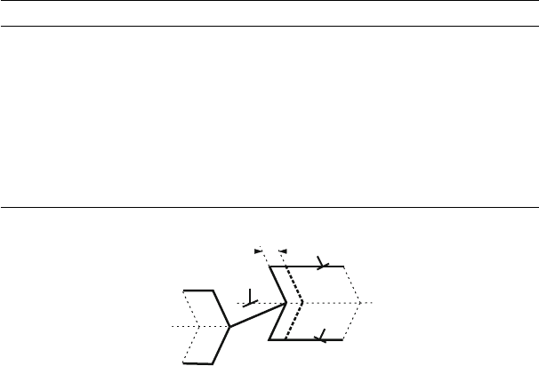
Fig. 9.27. Motion of a macrokink in a dislocation with 110 Burgers vector
decomposed according to (9.3). After [583]
The geometry and energy balance of both reactions are summarized in
Table 9.3. The energies are the prelogarithmic factors E
0
calculated in the
framework of anisotropic elasticity. According to the table, the reaction (9.4)
along 111 is slightly unfavorable in terms of the elastic energy factors of the
dislocations involved. The interaction energy is not considered.
Mills et al. [583] present a model of the diffusional motion of an edge
dislocation decomposed according to (9.3) by the spreading of constricted
macrokinks. They assume that the dislocation forms a constricted macrokink
of height h as outlined in Fig. 9.27. b
t
is the 110 total Burgers vector, and
b
c1
and b
c2
are the 100 Burgers vectors of the components. To shift the
macrokink by a distance ΔL, the area A has to be swept by the dislocation
with b
c1
acting as a vacancy source while the area B is swept by absorbing
these vacancies. Under very simplifying assumptions, the change in energy by
shifting the macrokink by a distance dL is
dW =(τb
t
h + σb
c1
d + E
110
− 2E
100
)dL. (9.5)
Here, τ is the shear stress acting on the macrokink with 110 Burgers vector.
This kink is of screw character. σ is the normal stress along a 100 direction
causing the dislocation with b
c1
to climb, whereas the dislocation with b
c2
does
not experience a climb force from the external stress. Finally, d is the width
over which the component dislocations have decomposed. The first term in

9.4 NiAl 353
(9.5) is the gain in energy by shifting the macrokink, the second one is the
loss in energy to form the vacancies on the dislocation with b
c1
. As described
above, the change in the self-energy by the decomposition E
110
−2E
100
is zero
for the decomposed edge dislocation.
During the motion of the macrokink by dL, a number of vacancies dN
have to be transferred from the vacancy source at the border of the area A
of the dislocation with Burgers vector b
c1
to the vacancy sink at B of the
dislocation with b
c2
, which equals
dN =
d
a
2
dL,
where a is the lattice parameter. The change in the elastic energy per
transferred vacancy is
w = −
dW
dL
dL
dN
=(τb
t
h − σb
c1
d)
a
2
d
.
Applying (4.83) with Δ (ΔG
f
)=w, the vacancy supersaturation at the source
dislocation is
Δc
v
= c
v
− c
v0
= c
v0
exp
w
kT
− 1
,
with c
v0
being the thermal equilibrium concentration of vacancies. In the limit
of Δc
v
c
v0
,thereis
Δc
v
≈
c
v0
w
kT
.
In a simple model, the vacancy flux from the source at A having a vacancy
concentration c
v0
−Δc
v
to the sink at B with a concentration c
v0
+Δc
v
occurs
by pipe diffusion along the component dislocations. Applying Fick’s law (4.91)
and considering that τ = σ/2 in the hard orientation, finally yields
v
k
=
4a
4
D
p
h/
√
2 − d
σ
d
3
kT
(9.6)
for the velocity of the macrokink. D
p
is the pipe diffusion coefficient. The
macrokink velocity exhibits a strong temperature dependence via the pipe
diffusion coefficient. It depends on the geometric parameters of the kink and
decomposition width, where the latter is particularly important. This param-
eter will further be considered in Sect. 9.5. Mills et al. [583] observed a good
agreement with experimental data by applying the geometric parameters of
the microstructural investigations and macroscopic data at a temperature of
600
◦
C, and by assuming that the activation energy of pipe diffusion is half
of that of bulk diffusion. For the mixed dislocations oriented along 111,the
motion occurs by combined glide and conservative climb. The character of the
climb-controlled motion is not jerky, but viscous.
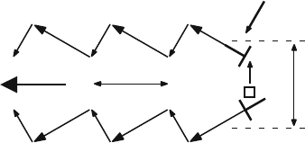
In a later model [571], it was considered that most dislocations orient
along 111 and that macrokinks have not been observed. According to the
354 9 Intermetallic Alloys
revised model, the movement of the dislocation consists of a succession of climb
and glide of the 100 component dislocations, as sketched in Fig. 9.28. The
forces acting on the product dislocations are the components of the external
stress, the elastic interaction between the products, a chemical force due to
the point defect super- or subsaturation and, in case of bowed segments, the
line tension. In the hard orientation, the external tensile or compressive stress
causes a pure climb force on one component dislocation and no force on the
other. This would lead to an increase in the decomposition width. The elastic
interaction between the components tries to arrange them perpendicular to
the glide plane of the total dislocation and then cause a radial attraction. In
addition, the dislocation climbing under the external stress changes the point
defect concentration away from the equilibrium, which results in a chemical
force on the other product dislocation. If the point defect flux generated at
one component is totally annihilated at the other one (conservative climb),
the dislocation couple will move along the glide plane of the nondecomposed
parent dislocation. The deviation of the dislocation along 111 from the edge
orientation results in a superposition of glide of the components on their low-
index glide planes. These processes may occur on an atomic scale as assumed
in the scheme of Fig. 9.28.
Srinivasan et al. [571] estimate the dislocation velocity by assuming the
climb to be diffusion-controlled (see Sect. 4.10.4). They arrive at a formula very
similar to (4.92). Instead of the cut-off radius R in the logarithmic term there
appears the decomposition width d. Accordingly, the velocity depends strongly
on the temperature via the diffusion coefficient and weakly on the decompo-
sition width. Inserting data for the deformation at about 600
◦
C, the (bulk)
diffusion coefficient of Ni at that temperature, an experimental decomposition
width of 2 nm for the dislocations aligned along 111, and a characteristic dis-
location density of 2 × 10
13
m
−2
yields a dislocation velocity in the 10
−5
s
−1
range, only one order of magnitude lower than that of the flow stress data. This
d
P
glide
climb
2
1/2
a
s
Fig. 9.28. Schematic drawing of the combined climb and glide motion of a decom-
posed dislocation with [110] Burgers vector arranged along [111] in NiAl. The image
plane is the (111) plane perpendicular to the extension of the dislocation. P is the
direction of propagation, d the decomposition width. The edge dislocation symbols
indicate the projections of the edge components of the 100 product dislocations. σ
is the projection of the applied stress onto the image plane. The open square marks
a diffusing vacancy. After [571]
9.5 FeAl 355
estimation is certainly no proof of the model. In particular, the assumption
of diffusion-controlled climb is questionable since it requires the characteristic
diffusion length to be great compared to the jog distance. This is certainly
not fulfilled at the small separation of the component dislocations. Besides,
the coordinated diffusion during the conservative climb in the elastic stress
field of the composite dislocation may be controlled rather by pipe diffusion
than by bulk diffusion. Thus, a comprehensive theory of the motion of these
dislocations still has to be established.
9.4.5 Summary
The dislocations with 100 Burgers vectors in NiAl, which are activated by
the deformation near room temperature along soft orientations, are pinned by
high jogs in the screw components. The jogs are created by double-cross slip.
They are stabilized against lateral motion and annihilation by lattice friction.
This is exactly the model suggested by Sriram et al. [549] for TiAl. It does
not lead to a flow stress anomaly. At elevated temperatures, the 100 disloca-
tions move in a viscous way pointing at the operation of a diffusion-controlled
mechanism. In the hard orientation, dislocations with 111 and 110 Burg-
ers vectors are active at high temperatures. When moving on {110} planes,
the 110 dislocations may be very straight and oriented along the edge and
mixed 111 directions. As suggested by Srinivasan et al. [571] and in the
present book, the straight oriented arrangement may result from a decompo-
sition into dislocations with 100 Burgers vectors. The preferred orientations
are the intersection lines between the glide planes of the parent dislocation
and low-index glide planes of the product dislocations. The decomposition may
occur by glide and is therefore different from the climb dissociation observed
by H. Saka et al. in several materials (e.g., in β brass [584]). The decom-
posed dislocations cannot move by glide alone but by the aid of conservative
climb, i.e., a diffusional flow of vacancies from one product dislocation to the
other. It will be discussed in the following sections that this model need not
be restricted to dislocations with 110 Burgers vectors in NiAl, but may be
more general.
9.5 FeAl
Like NiAl, FeAl has the B2 structure with 111 and 100 Burgers vectors.
The dominating slip planes are of {110} type. FeAl single crystals show a flow
stress anomaly with a maximum at about 550
◦
C as shown in Fig. 4.40.
9.5.1 Microscopic Observations
The following data originate from experiments on an Fe-43at%Al single crystal
[8], which was annealed at 400
◦
C for 1 week followed by slow cooling to room
356 9 Intermetallic Alloys
temperature to anneal out the excess point defects originating from crystal
growth. Specimens for in situ straining experiments were cut with a [753]
tensile axis and (1
¯
21) foil planes. Samples for macroscopic compression tests
were prepared with the same loading axis and a (13
¯
50 53) side face about
10
◦
off (0
¯
11). This orientation favors slip on the (101)[11
¯
1] system. Notable
orientation factors also have (011)[11
¯
1], (101)[010], and (011)[100].
In FeAl, there is a transition of the dominating Burgers vector from 111
to 100 [585,586] just at the temperature of the flow stress peak, which might
cause the anomaly [587]. However, rapid quenching after deformation showed
that dislocations with 111 Burgers vectors dominate during deformation at
the high strain rate of 5 × 10
−2
s
−1
even at the high temperature of about
650
◦
C [588]. Similarly, it was observed that the deformation at the peak tem-
perature of 550
◦
C started by dislocations with 111 Burgers vectors, whereas
those with 100 Burgers vectors appeared only after a few percent of plastic
strain [589]. Conventional TEM in the high-voltage electron microscope of
macroscopically deformed specimens was performed to secure that the defor-
mation of the present material is carried by dislocations of the same Burgers
vector up to the flow stress maximum. In Fig. 4.40, the temperatures at which
dislocation structures were studied are marked by dashed grey vertical lines.
The microstructure with dislocations of 111 Burgers vectors after defor-
mation at 495
◦
C was presented in Fig. 3.22. Dislocations with these Burgers
vectors prevail up to the flow stress maximum. Stereo image pairs show that
most dislocations are not confined to their slip planes indicating the impor-
tance of climb. Further deformation at 564
◦
C activates dislocations with 100
Burgers vectors as demonstrated before in Fig. 1.4.
Due to elastic instabilities, many dislocation lines of both Burgers vectors
exhibit an angular shape with a sharp knee. Some of them are indicated in the
figures. If the overall orientation of a dislocation lies in the unstable range, the
dislocation decomposes into stable segments as labeled by A in Fig. 3.22. In
[590], a comprehensive study was given of the elastic properties of dislocations
with all relevant Burgers vectors in B2 Fe–Al of different composition. Accord-
ing to that, dislocations with 111 and 100 Burgers vectors are elastically
unstable in certain orientation ranges. The insets of Figs. 3.22 and 1.4 present
the calculated shapes of dislocation loops on the (101) plane using the line
tension model in anisotropic elasticity with elastic constants from [591]. The
line tension maxima and minima of the 111 dislocations are not located at
the screw and edge orientations. They differ by a factor of about 8, resulting in
the elongated shape of the equilibrium loop. Between about 38
◦
and 55
◦
, i.e.,
for orientations close to [10
¯
1], the dislocations are unstable resulting in edges
in the dislocation line. These knees and preferential orientations are evident
in Fig. 3.22, which also shows many mixed dislocations having decomposed
into a zig-zag shape, e.g., at A. The energy of the [010] dislocation shows an
anomalous decrease with increasing edge character with its minimum at about
125
◦
. The shape of this dislocation is symmetric around the Burgers vector
direction with relatively flat segments at the two 111 orientations. The screw
9.5 FeAl 357
0.5 µm
g
b
1
b
2
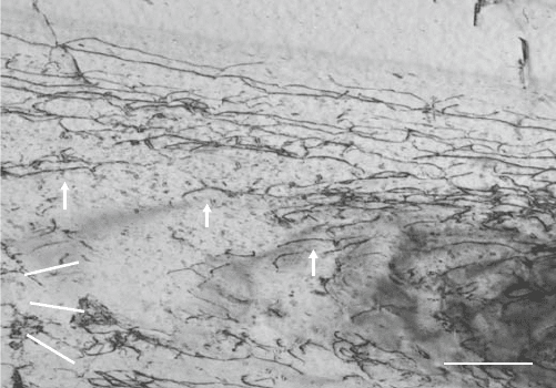
Fig. 9.29. Dislocations in Fe-43Al moving during an in situ straining experiment
at room temperature. g =(10
¯
1) near the [1
¯
21] pole. g is parallel to the trace of the
(101) primary slip plane. b
1
and b
2
are the projections of the [11
¯
1] and [
¯
111] Burgers
vectors. From [8]. Copyright Elsevier Ltd. (2005)
orientation is unstable in the range between about 14
◦
and −14
◦
.Theinsta-
bility of the screw direction and the preferential orientations are obvious from
Fig. 1.4. Apparently, the edge orientation seems to be another preferential
orientation which is not described by the elastic dislocation properties.
In Fig. 4.40, the temperatures at which in situ straining experiments
were performed in the HVEM are indicated by black vertical lines. At
room temperature, dislocation motion was observed in the plastic zone of
a crack. Figure 9.29 shows the dislocation structure during deformation. The
projections of the Burgers vectors are marked. Moving near-screw dislocations
with Burgers vector b
1
are labeled by arrows. In the upper part of the figure,
long dislocations of 30
◦
character have developed. All dislocations bow out
between cusps in the dislocation lines. The distances l between the obstacles
are in the range of 0.1 μm.
The dynamic behavior of the dislocations is demonstrated in the following
video sequences.
Video 9.12. Motion of dislocations with 111 Burgers vectors in Fe-43at%Al at
room temperature: The clip consists of four sequences. Compared to the others, the
first one is taken at a lower magnification. The dislocations move in a jerky way
over distances longer than the segment length between the pinning points. The long
dislocations are of near-screw character.
In situ experiments at 363
◦
C, i.e., when the flow stress begins to increase,
show straight slip traces belonging to glide on {110} planes, with cross slip
events between different such planes. The dislocations with 111 Burgers vec-
tors consist of straight segments of two orientations. One is consistent with
358 9 Intermetallic Alloys
1 µm
b
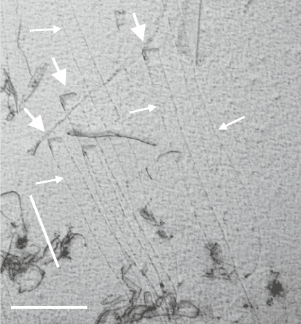
Fig. 9.30. Slip traces and dislocations with 111 Burgers vectors moving during
in situ straining in Fe-43at%Al at 530
◦
C. g =(10
¯
1) near the [1
¯
21] pole. From [8].
Copyright Elsevier Ltd. (2005)
the screw direction, whereas the other one corresponds to a mixed orientation
with a large edge component, which may be 111 on the respective {101}
plane. At 530
◦
C, i.e., in the anomaly range of macroscopic deformation tests,
the slip traces (thin arrows in Fig. 9.30) are curved pointing at the superpo-
sition of climb or cross slip in addition to glide. Nevertheless, the traces are
close to those of the (011) planes. The dislocations (thick arrows) imaged with
the (10
¯
1) reflection belong to the primary [11
¯
1] Burgers vectors. The projec-
tions of the straight segments are again consistent with the screw orientation
and the 60
◦
character on the (011) plane. The next video shows the motion
of such dislocations.
Video 9.13. Motion of dislocations with 111 Burgers vectors in Fe-43at%Al at
530
◦
C: The dislocations of angular shape move very slowly in a viscous way.
In addition, slip bands occur with dislocations that are extinguished at
g =(10
¯
1). These dislocations can be imaged with a (211) g vector at the
[1
¯
31] pole as demonstrated in Fig. 9.31 taken at 447
◦
C. They are also invisible
with g = (200) so that their Burgers vector is [010]. The orientation of the slip
traces suggests again (101) slip planes. These dislocations are straight, with
their projections corresponding to 111 directions, i.e., the angle between the
Burgers vectors and the dislocation lines is 54.7
◦
. Their motion is recorded in
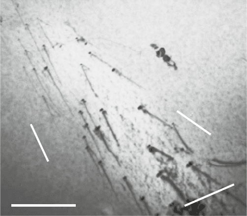
9.5 FeAl 359
1µm
g
p
1
p
2
Fig. 9.31. Dislocations with 100 Burgers vectors moving during in situ deforma-
tion of Fe-43Al at 447
◦
C. g = (112) near the [1
¯
31] pole. Projections p
1
=[71
¯
4] of
[
¯
111] direction and p
2
=[
¯
417] of [11
¯
1] direction. From [8]. Copyright Elsevier Ltd.
(2005)
Video 9.14. They move and multiply in bands separated from the bands with
111 dislocations.
Video 9.14. Motion of dislocations with 100 Burgers vectors in Fe-43at%Al at
447 and 530
◦
C: The dislocations of a straight oriented shape move viscously. Even
at a temperature lower than in Video 9.13, the 100 dislocations move faster than
those with 111 Burgers vectors. After unloading, they relax into a curved shape.
At high temperatures far above the flow stress maximum (near 700
◦
C),
the dislocations show a totally different behavior, which is documented in the
following video.
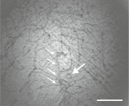
Video 9.15. Dynamic formation and annihilation of dislocations in Fe-43at%Al
at 700
◦
C: Smoothly curved dislocations move viscously in a very irregular way
pointing at a combination of glide with rapid climb. New dislocation length is cre-
ated continuously by certain segments bowing out. On the other hand, dislocation
segments coming across each other frequently annihilate, so that the dislocation den-
sity remains constant on a low level over a long time of observation. At L near the
end of the sequence, a small loop is created by a moving dislocation, which shortly
afterward collapses again. The loop is also shown in Fig. 9.32. When the dislocations
stop moving, they form straight segments, the projections of which are consistent
with the three 100 line directions.
360 9 Intermetallic Alloys
1 µm
Fig. 9.32. Frame from Video 9.15 showing the blurred image of a moving dislocation
marked by small arrows and a dislocation loop indicated by a thick arrow.From[8].
Copyright Elsevier Ltd. (2005)
The irregular nonplanar motion of the dislocations suggests that, at this
high temperature, climb is not only a process of recovery but also a mode of
dislocation motion.
9.5.2 Macroscopic Deformation Parameters
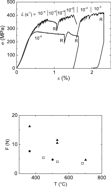
Figure 9.33 shows two stress–strain curves at 550
◦
C with sections taken at
the different strain rates indicated. The curves are either smooth or serrated
depending on the strain rate and, in general, also on the temperature. Smooth
deformation curves occur only at room temperature for strain rates above
10
−6
s
−1
, and above about 550
◦
for strain rates less than 10
−3
s
−1
.Below
550
◦
C, optical microscopy shows single slip on localized bands corresponding
to the (101) primary slip plane. Above that temperature, traces are revealed
belonging to the (011) plane.
As mentioned earlier, the temperature dependence of the yield stress
was presented before in Fig. 4.40. The curve consists of three ranges, a low-
temperature range of a normal temperature dependence, i.e., with a slightly
decreasing flow stress between room temperature and about 350
◦
C, a range of
an anomalous increase between about 350 and 550
◦
C, and a high-temperature
range above 550
◦
C with again a normal decrease of the flow stress. In this
range, very strong yield points occur. Figure 4.40 presents the lower yield
9.5 FeAl 361
Fig. 9.33. Stress–strain curves of Fe-43at%Al deformed at 550
◦
C at different strain
rates ˙ε. R are stress relaxation tests. Data from [8]
Fig. 9.34. Dependence of the load to achieve dislocation velocities suitable for obser-
vation in the HVEM for three in situ experiments including temperature changes.
Each symbol belongs to one experiment. Data from [8]
points. The upper yield point of 342 MPa at 594
◦
C has almost the same value
as the stress maximum at 550
◦
C.
The tensile stage for the in situ straining experiments in the HVEM allowed
the measurement of the force acting on the micro-specimens. During the exper-
iments at higher temperatures, several times a single specimen was deformed
successively at different temperatures. The straining stage was controlled in
such a way that dislocation velocities were achieved in the range that can well
be recorded (about 10–1,000nm s
−1
). In Fig. 9.34, these loads are plotted ver-
sus the temperature for three in situ experiments. Each symbol corresponds
to one specimen deformed at different temperatures. In all experiments, there
is a continuous decrease of the loads with increasing temperature, i.e., the
anomalous increase of the flow stress observed in macroscopic experiments
did not occur during the in situ tests.
The strain rate sensitivity of the flow stress was studied by stress relaxation
tests. The relaxation curves are quite straight or have the usual curvature
