McKinney J.D., Warnick C.C. Microhydropower Handbook Volume 1
Подождите немного. Документ загружается.

hl =
fc x La x Hf
100
(4.5.4)
where
hl =
head loss in feet
fc =
fc friction loss correction factor from Table 4.5-2
La =
adjusted length of penstock in feet
Hf =
head loss factor from Figure 4.5-2 or 4.5-3.
EXAMPLE: From the previous examples:
La
= 1091 feet
Hf
= 0.34 (Figure 4.5-4)
* From Table 4.5-2:
Steel: fc = 1.16
PE: fc
= 0.77
FRP: fc = 0.77
For steel pipe
.
hl
= 1.16 x 1091 x 0.34
100
hl
= 6.2 feet
4.5-18
.
: l
i,.
. .
.
For PE and FRP
h, =
1.77 x 1091 x 0.34
----
100
hl =
2.9 feet
This loss must be subtracted from the site"s available head. Since it
is a friction loss, it will not be available to produce power.
EXAMPLE:
If the pool-to-pool head at the developers site is 42 feet,
the net effective head for the site is 42 - 2.9 = 39.1 feet.
You must recognize that a number of pipe diameter and material combin-
ations exist for transporting the desired flow from intake to turbine. The
optimum pipe diameter tends to be a site-specific decision, and several
alternative configurations should be evaluated.
The following general
suggestions may help with this evaluation.
Ia
Penstock diameter (and cost) can be reduced until the maximum
recommended velocity of 5 fps is reached. *This will increase
friction losses.
0
Penstock friction (energy) loss can be reduced by increasing the
diameter and therefore decreasing velocity. Offsetting costs may
be realized if the reduced velocity reduces the pipe pressure
class.
0
Penstock friction loss can also be reduced by selecting alterna-
tive pipe materials having a lower loss coefficient.
The Category 2 developer may want to compare energy loss and pipe costs
to arrive at an optimum pipe diameter.
NOTE: Higher friction in the pipe reduces the potential of freezing
in the pens&k.
See Subsection 4.5.7.
4.5-19
- -.-. .-. . ..- . ._ _ -.. . _ _ _ -__ __ _
.
j ~.,
-
4.5.5 Valves
During the life of the generating facility, it will periodically be
necessary to stop flow to the turbine for maintenance and repair or to
dewater the penstock for repair.
Also, reaction turbines use valves to
control flow and to prevent overspeed.
For this reason,
suitable valves or
gates at either end of the penstock should be incorporated into the
development plans.
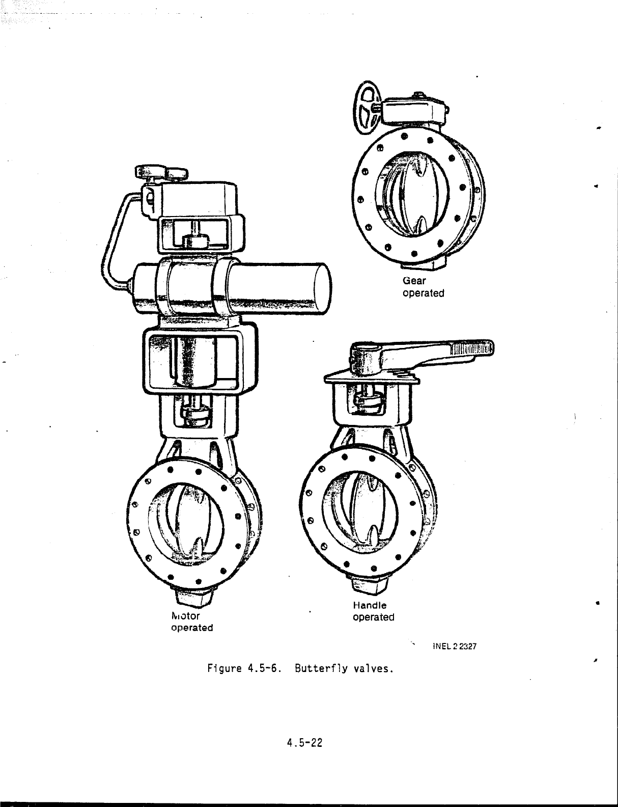
Various types of valves can be used. For gates in canals or on corru-
gated metal pipe,
slide gates are ideal (Figure 4.4-8). Butterfly valves
work well at either end of the penstock. Figure 4.5-5 is a photograph of a
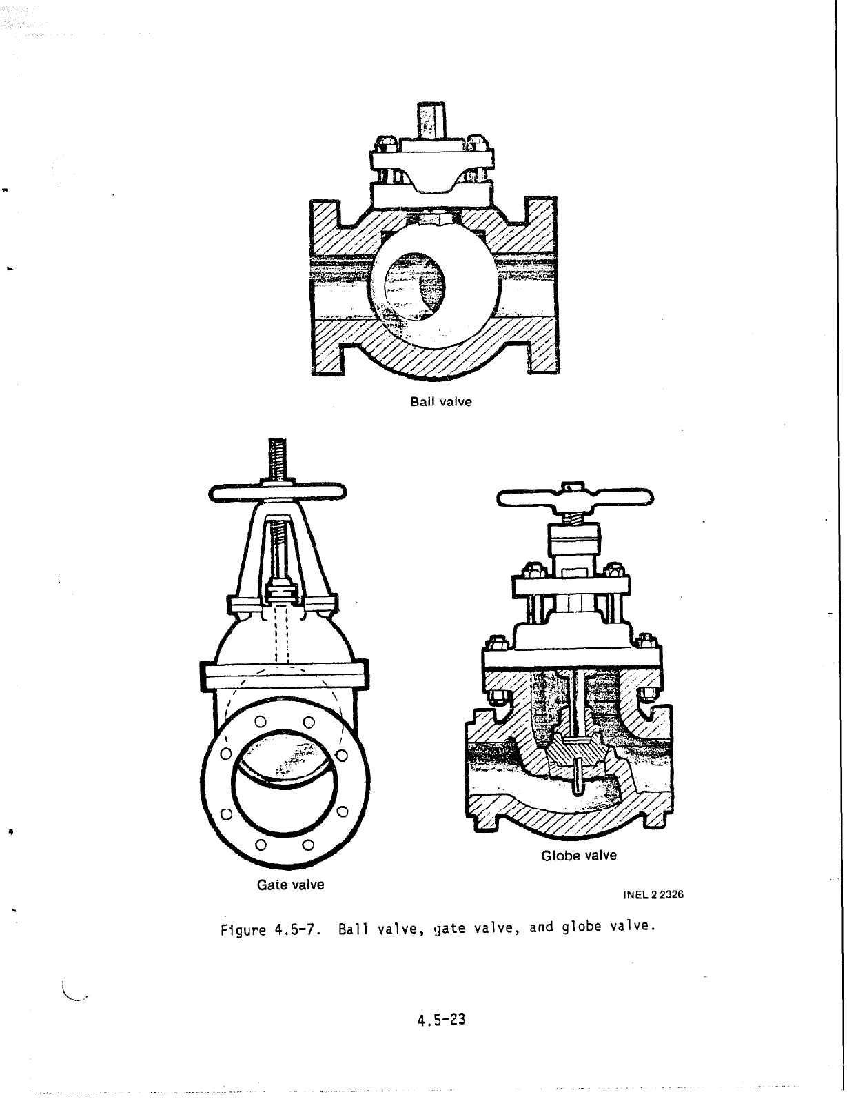
butterfly valve body and disc, and Figures 4.5-6 and 4.5-7 present drawings
of butterfly, gate,
ball, and globe valves.
4.5.5.1 Penstock Intake.. As discussed in the Intake subsection (4.4),
a slide gate or butterfly valve can be incorporated into the structure at
the intake of the penstock. The penstock inlet downstream from the valve
must be open to the atmosphere to prevent the formation of a vacuum during
penstock dewatering.
This can also be a part of the inlet design, or an
air&admission
pipe with the
(Figure 4.4-l
4.5.5.2
high point ex
release valve
valve can be added.
This could consist of an open vent stand-
top elevation higher than the water surface at the.forebay
1.
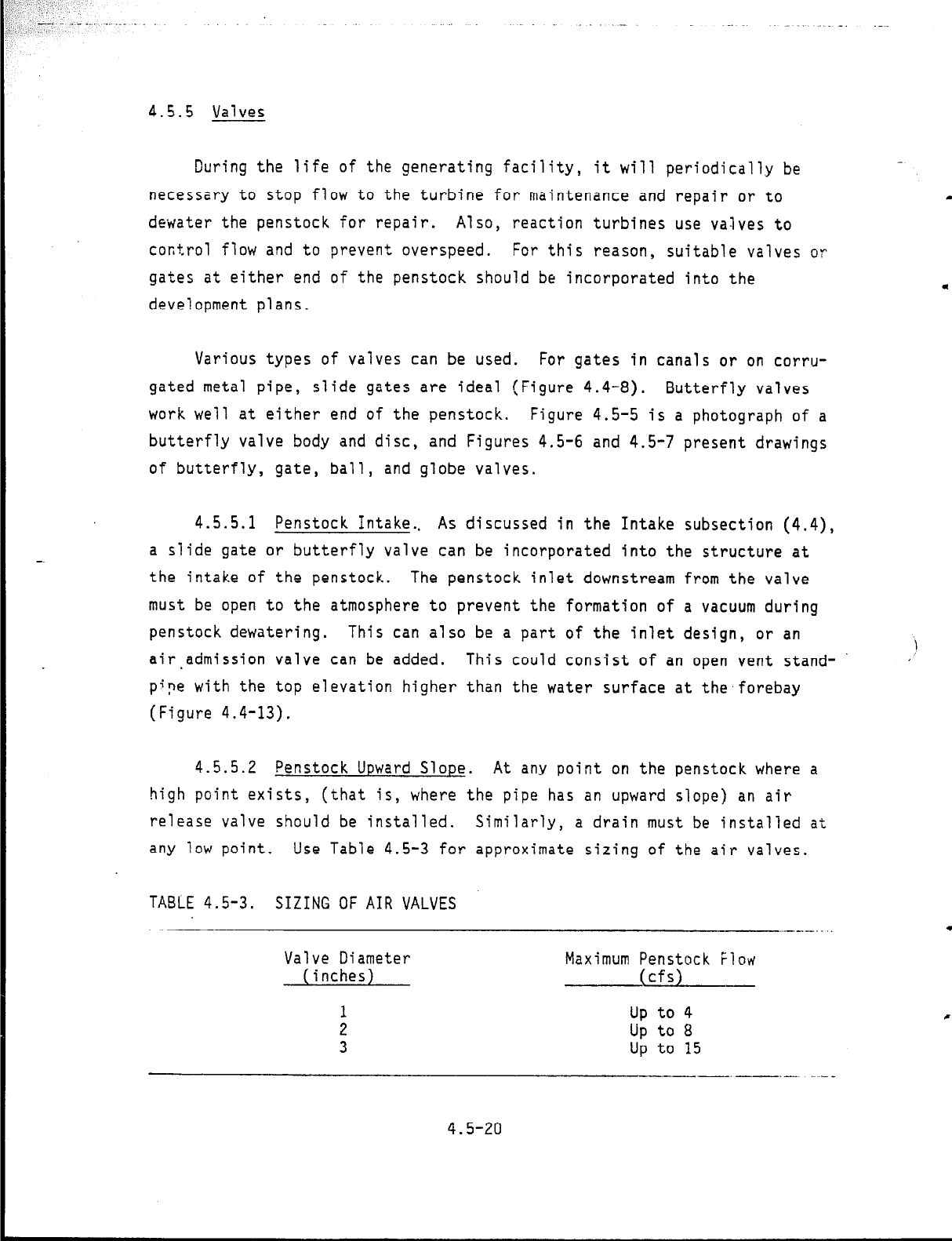
Penstock Upward Slope. At any point on the penstock where a
sts, (that is, where the pipe has an upward slope) an air
should be installed.
Similarly, a drain must be installed at
any low point, Use Table 4.5-3 for approximate sizing of the air valves.
TASLE 4.5-3.
SIZING OF AIR VALVES
Valve Diameter
(inches)
:
3
Maximum Penstock Flow
(cfs)
up to 4
up t0 a
up to 15
--__ -.-- ..~__
4.5-20
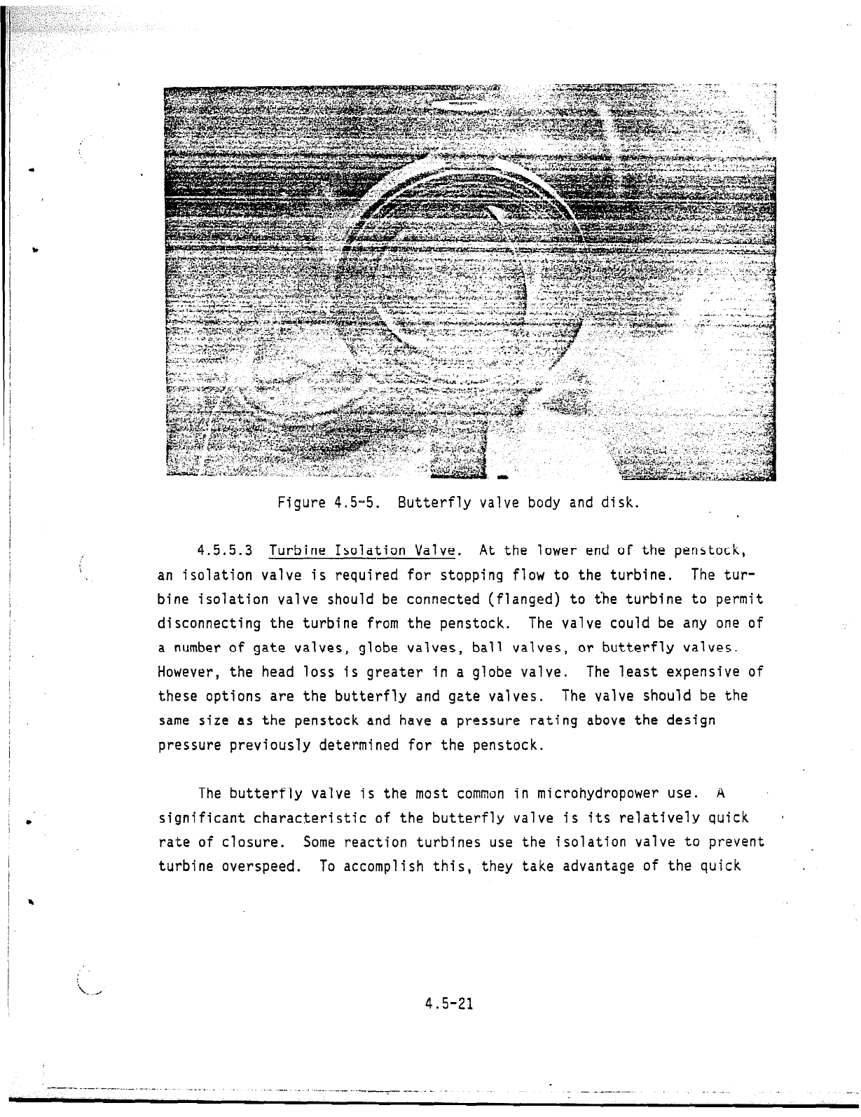
Figure 4.5-5.
Butterfly valve body and disk.
4.5.5.3 Turbine Isolation Valve. At
an isolation valve is required for stopping
bine isolation valve should be connected (f
disconnecting the turbine from the penstock
a number of gate valves, globe valves, ball
i
he lower end of the penstock,
flow to the turbine. The tur-
anged) to the turbine to permit
The valve could be any one of
valves, or butterfly valves.
However, the head loss is greater in a globe valve. The least expensive of
these options are the butterfly and gate valves. The valve should be the
same size as the penstock and have a pressure rating above the design
pressure previously determined for the penstock.
The butterfly valve is the most common in microhydropower use. A
significant characteristic of the butterfly valve is its relatively quick
a
rate of closure.
Some reaction turbines use the isolation valve to prevent
turbine overspeed.
To accomplish this,
they take advantage of the quick
4.5-21
---_._ - .---.. _._-.. - .
._..
_ - . .._-..._ - .._.
-I --‘- - -
- _ --.-- -.
--
r;
_ _
w
kl3tor
operated
‘.
INEL22327
Figure 4.5-6.
Butterfly valves.
Gear
operated
Handle
operated
4.5-22
Ball valve
.
Globe valve
.
Gate valve
INEL 2 2326
Figure 4.5-7.
Ball valve, gate valve, and globe valve.
4.5-23
closing characteristics of the butterfly valve. When this is done, some
other means must be designed into the penstock to eliminate surge pressure
on the penstock.
If no method is provided to eliminate surge, care must be
taken to close the valve slowly.
Providing a geared,
motor-operated valve
with backup power supply and with slow closure rate will reduce the
potential for creating excessive surge pressures.
Surge pressure can create havoc with a penstock. It can cause a pipe
to jump and send a wave of pipe movement up the length of the penstock. If
the pressure is high enough, the penstock will rupture and cause other
damage or even injury.
CAUTION: The water will actually force a butterfly valve closed after
it is halfway closed; therefore, be very careful if you plan to use a handle
type actuator (Figure 4.5-6). The handle has flown out of the hand of more
than one unsuspecting operator. And, of course, a valve that is slammed
shut will create surge pressure.
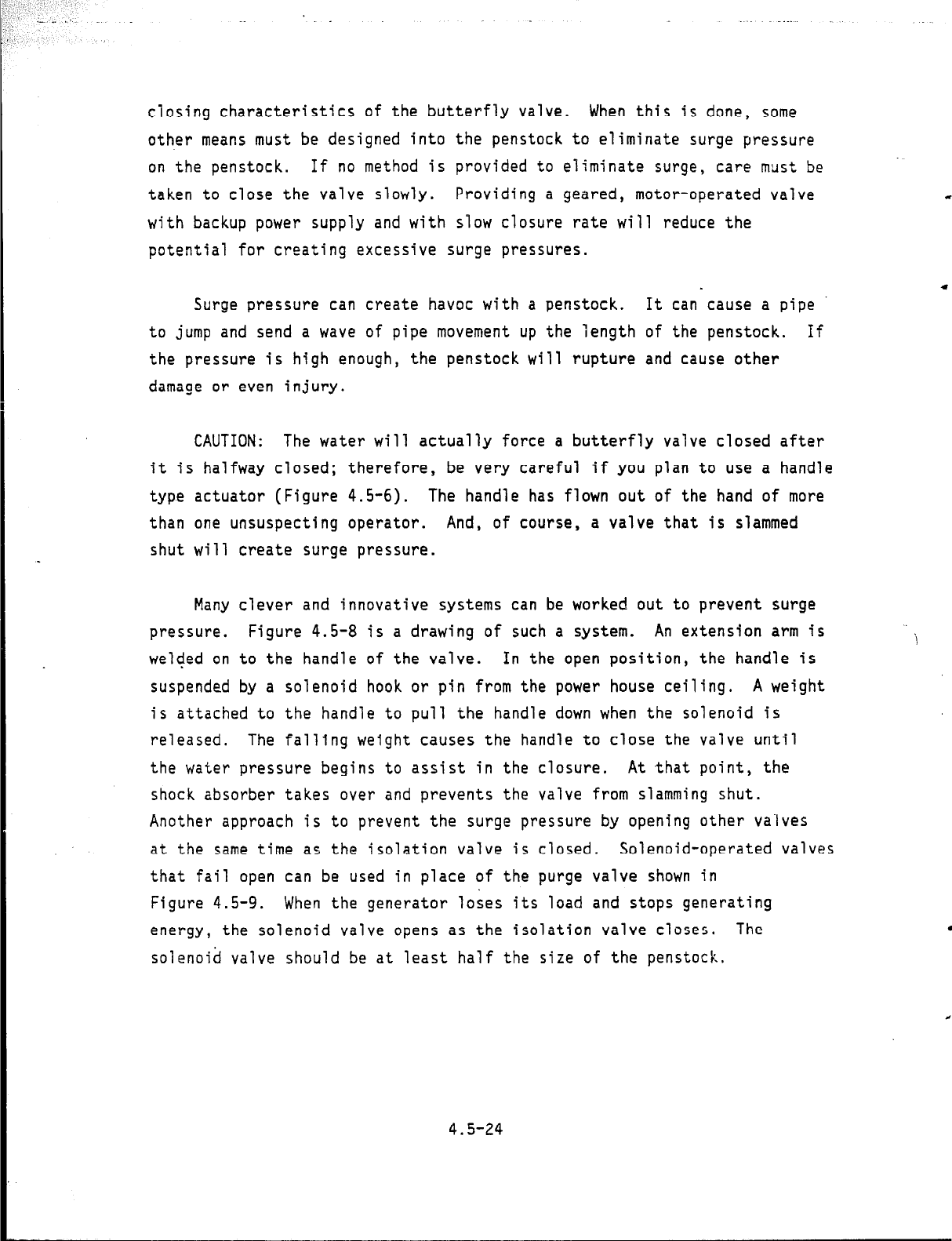
Many clever and innovative systems can be worked out to prevent surge
pressure.
Figure 4.5-8 is a drawing of such a system. An extension arm is
i
welded on to the handle of the valve.
In the open position, the handle is
suspended by a solenoid hook or pin from the power house ceiling.
A weight
is attached to the handle to pull the handle down when the solenoid is
released. The falling weight causes the handle to close the valve unti
the water pressure begins to assist in the closure.
At .that point, the
shock absorber takes over and prevents the valve from slamming shut.
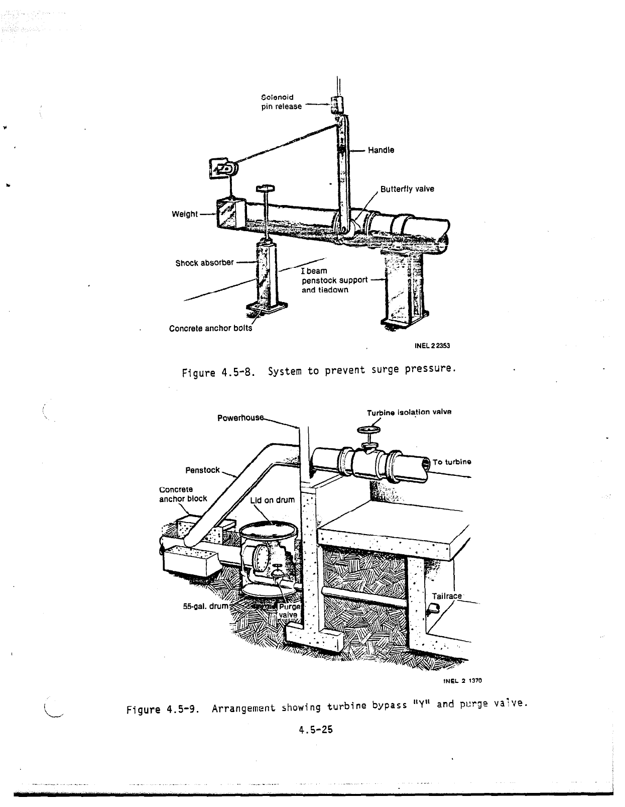
Another approach is to prevent the surge pressure by opening other valves
at the same time as the isolation valve is closed.
Solenoid-operated valves
that fail open can be used in place of the purge valve shown in
Figure 4.5-9. When the generator loses its load and stops generating
energy, the solenoid valve opens as the isolation valve closes. The
solenoid valve should be at least half the size of the penstock.
4.5-24
Soienoid
1
pin release -
Shock absorber
penstock
support
Concrete anchor bolts’
Figure 4.5-8. System
INEL22353
to prevent surge pressure.
Turbine isolaJion valve
55gal. drum,
INEL 2 1370
Figure 4.5-9.
Arrangement showing turbine bypass "Y" and purge valve.
4.5-25
Another possibility with low head is a stwipe at the lower end of
the penstock.
The pipe can either be opened to the atmosphere or sealed
with air in the pipe under pressure.
The air ir the pipe will act as a
shock absorber for the surge pressure. If the @ipe is sealed, provision
should be made to check the water level in the pfpe, since the air pocket
may have to be replaced periodically.
The air till be absorbed into the
water over long periods of time. Also, standpip have a tendency to freeze
in the cold months because the water is stagna&L If a standpipe is used,
heaters and insulation should be added to keep %e water from freezing.
4.5.5.4 Turbine Bypass "Y". Figure 4.5-9 fiows two additional
recommendations for penstocks. To reduce the perribility of getting foreign
material into the turbine, it is advisable to E& a "Y" connection off the
main penstock and have the turbine branch of thepenstock above the bypass.
To keep the turbulance of the "Y" out of the t&&Me, place the "Y" at least
10 pipe diameters above the turbine, e.g., placea 14-inch pipe 140 inches
above the turbine.
The second recommendation for the "Y' is a Qurge valve. This would
consist of a 4- to 6-inch valve on a tee near t& lower end of the bypass.
‘\
In the case of the figure, the purge valve and W blind flange on the pen- '
stock are housed in a partially buried 55-gallon drum cut to fit. The drum
with lid acts as a manhole and can help prevent*eezing of the valve.
This valve is piped tc discharge into the tailwar and serves several
functions. Among these are:
#
A "blowoff" cleanout for silt or sand Wat has been carried down
the penstock.
0
A bypass valve to maintain.flow in the penstock if the turbine is
shut down (for example, to prevent fre&ng).
a
CAUTION:
The water in the penstock is underr pressure. The purge valve
and discharge pipe must be anchored. In additim, the discharge pipe
should be directed into the tailrace.
If a reamon turbine is used,
4.5-26
_’
the discharge should be into the tailrace pool of water below the draft
tube.
The water in the pool will help to dissipate part of the energy.
You can never be too careful when dealing with a pressurized penstock.
*
. Remember, there is more potential energy in a penstock than the electrical
energy that the generator generates,
and both can be very dangerous when
not handled correctly.
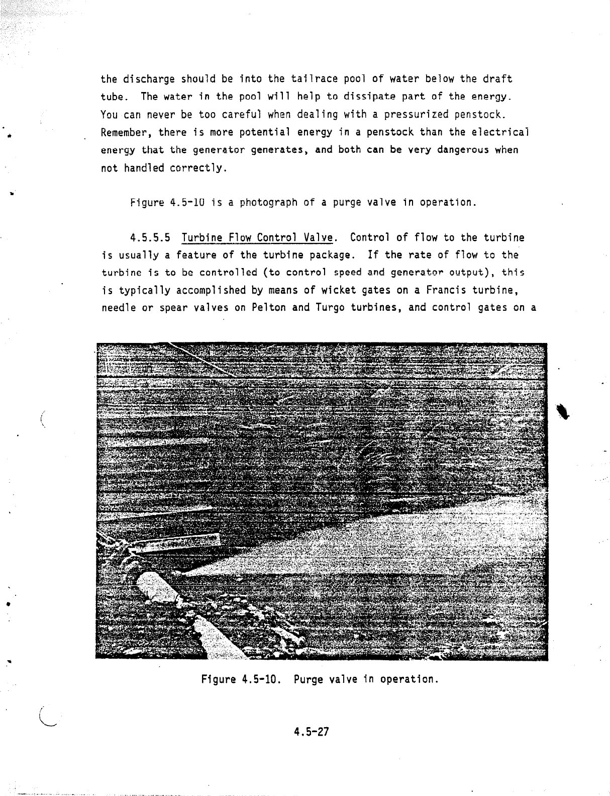
Figure 4.5-10 is a photograph of a purge valve in operation.
4.5.5.5 Turbine Flow Control Valve. Control of flow to the turbine
is usually a feature of the turbine package.
If the rate of flow to the
turbine is to be controlled (to control speed and generator output), this
is typically accomplished by means of wicket gates on a Francis turbine,
needle or spear valves on Pelton and Turgo turbines, and control gates on a
.
Figure 4.5-10. Purge valve in operation.
4.5-27
--. _.. .- _
.._.
._
_-
__.._
_