Massoud M. Engineering Thermofluids: Thermodynamics, Fluid Mechanics, and Heat Transfer
Подождите немного. Документ загружается.

752 VIc. Applications: Fundamentals of Turbomachines
Total dynamic discharge head is the static discharge head plus the velocity
head plus the discharge friction head.
2
hh
2
ee
dePdf
PV
ZZ
gg
ρ
§·
=++−+
¨¸
©¹
Total dynamic head is the difference between total dynamic discharge and to-
tal dynamic suction head:
22
Hhh
22
ee ii
eifs
PV PV
ZZ
gg gg
ρρ
§·§·
=++−+++=
¨¸¨¸
©¹©¹
where hhh
fdfsf
=+
Vapor pressure of a liquid is the absolute pressure at which liquid vaporizes
and is in equilibrium with its vapor phase. If the liquid pressure drops below the
vapor pressure, the liquid boils. If liquid pressure is greater than the vapor pres-
sure, then the liquid vaporizes at the interface between the two phases. The vapor
pressure of water at 80 F (27 C), for example, is P
V
= 0.50683 psia (3.5 kPa).
Similar definition is given in Section IIa.1.4. If pressure at the eye of the pump
drops below the vapor pressure then the pump begins to cavitate.
Cavitation is the major cause of damage to pumps and valves where liquid ex-
periences a large and sudden pressure drop. Cavitation is defined as formation,
via vaporization, and subsequent collapse, via condensation, of vapor bubbles in a
liquid. A pressure drop to or below the liquid vapor pressure coupled with exist-
ing nuclei (tiny voids containing vapor or gas) results in liquid vaporization.
These voids appear as tiny bubbles that will grow if the surrounding pressure re-
mains at or below the vapor pressure of the liquid or they will collapse at higher
pressures. Pressure drop occurs at such locations as tip of a propeller, edges of a
thin-plate orifice, or seats of a valve. These unrecoverable pressure losses in these
places are associated with dissipation of energy, which constitutes the loss coeffi-
cient of valves and fittings. Collapse of bubbles in higher-pressure regions is as-
sociated with rapid pressure fluctuations that will eventually result in erosion and
pitting of the hydraulic structure.
There are various means of preventing cavitation, primarily depending on the
type of the hydraulic system. Prevention of cavitation in a pump is discussed in
Section 3. In some hydraulics systems, it may be possible to introduce a gradual
pressure drop to the flow. Cavitation control valves may use a tortuous flow path,
cascaded orifices, or a combination of both to cause high velocity hence, large lo-
cal frictional losses. Another means of preventing material erosion due to cavita-
tion is to use erosion resistant materials at locations prone to cavitation, such as
the use of stainless steel for a turbine blade, valve seat, or pump impeller. As
shown in Figure VIc.2.2, during operation we must ensure that P
eye
> P
vapor
.
Best efficiency point (BEP) is an operation mode at which the pump efficiency
is a maximum. While pumps should be operated at their BEP, it is especially im-
2. Centrifugal Pumps 753
portant for pumps that operate with liquids with abrasive contents. At the BEP,
the angle at which the impeller and the liquid meet is optimized, helping to reduce
impingement and minimize erosion. In this chapter, the pump parameters at BEP
are shown with subscript “o”.
Net positive suction head as required by the pump is usually given for the best
efficiency point by the pump manufacturer. The available net positive suction
head (NPSH
A
) defined as
()
2
/2
PP v
P
VP+−is obrained from:
()
h
iv
APifs
PP
NPSH Z Z
gg
ρρ
=−−−−
VIc.2.1
where point i is on the surface of the source reservoir and point P is at the pump
inlet. However, for large pumps, point P should be taken at the top of the impel-
ler. Pressure at the source reservoir is P
i
. If the reservoir is open to atmosphere
then P
i
= P
atm
. In Equation VIc.2.1, P
v
shows the vapor pressure of the liquid at
operating temperature. For example, water vapor pressure at P = 14.7 psia and T
= 80 F is about P
v
= 0.5 psia. Finally, h
fs
represents frictional head loss in the suc-
tion piping and is found from Equation IIIb.3.12 with L = s +
δ as depicted in
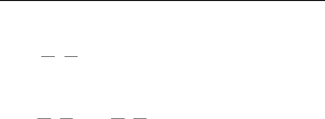
Figure VIc.1.1 where h
fi
is friction head loss between the suction-side reservoir
and pump inlet and P
v
is the working liquid saturation pressure at operating tem-
perature.
i
s
(a) Arrangement Helps NPSH
A
Z
i
Z
P
δ
P
i
δ
(b) Arrangement Hurts NPSH
A
P
Z
i
Z
P
s
Figure VIc.1.1. Two arrangements for pump suction (P
i
is maintained throughout the
pumping process)
Shutoff head is the maximum head a pump develops corresponding to the
minimum flow rate.
Runaway speed is the speed a centrifugal pump would reach when the pump
impeller runs in the reverse direction. This occurs upon failure of the discharge
valve to close when a running pump is stopped under a high static head.
Design pressure is the maximum pressure the pump casing can be exposed to
before being structurally damaged.
Rated conditions are the values of pump head and pump flow rate correspond-
ing to maximum pump efficiency. For all practical purposes, pumps should be
operated at the BEP. However, we recognize that deviations will occur from

754 VIc. Applications: Fundamentals of Turbomachines
pump conditions during operations primarily variations in demand for flow rate.
The more the operating conditions deviate from the BEP, the more a pump would
be subject to degradation in performance and long-term deterioration of its com-
ponents.
Hydraulic horsepower is the power transferred to the fluid to deliver a flow
rate of
V
at a total dynamic head of H. To calculate the pumping power, we use
HYD
W
= FV = (∆PA)( V
/A) = HVg
ρ
= m
gH.
Brake horsepower is the power delivered by the prime mover to drive the
pump (
ȦT=
BHP
W
), where ω is the shaft angular velocity (radian/s) and T is the
shaft torque delivered by the prime mover.
Pump efficiency is the ratio of hydraulic horsepower to brake horsepower,
mhv
HYD
W
ηηηη
==
ȦT
.
Substituting values, efficiency can be found from
()
T2/Vh Ng
πρη
=
where head
is in ft, flow rate in GPM, torque in ft·lbf, and impeller speed in rpm.
Volumetric efficiency, as a component of pump efficiency, is defined as
)VV/(V
Lv
+=
η
where
L
V
is the leakage flow rate to the casing from the im-
peller-casing clearance.
Hydraulic efficiency is defined by three types of losses occurring in the pump.
The first type is the shock loss at the impeller inlet (eye) due to imperfect match
between inlet flow and the impeller entrance. The second type is due to frictional
losses in the impeller. The third type is the circulation loss caused by the imper-
fect match between the exit flow and the impeller outlet. Hence, we find
)h/h(1
sfh
−=
η
.
Mechanical efficiency is defined by the losses in pump bearings, packing-
glands, or mechanical seals and other contact points. If
f
W
is the power wasted
in all the contact points,
)/(1
BHPfm
WW
−=
η
. Improvement of the pump seal
and the bearing material may increase pump efficiency by as much as 2%.
Priming refers to the inability of rotodynamic pumps to operate if non-
condensable gases have leaked into the pump. In positive displacement pumps,
the moving element, whether piston, gear, screw, or sliding vane, readily evacu-
ates gases from the pump. For this reason, positive displacement pumps are con-
sidered to be self-priming.

3. Dimensionless Centrifugal Pump Performance 755
3. Dimensionless Centrifugal Pump Performance
Earlier in this section we identified three groups containing pertinent pump
parameters, (
V
, ∆P), (D, ω,
ε
), and (
ρ
,
µ
) . To obtain a relation for
(
)
εµρρ
,,,,,VH DNfgP
pump
==∆
with H being total dynamic head, we note
that there are a total of seven variables. Choosing
ρ
, D, and ω to represent the
three primary dimensions mass, length, and time, we can identify four dimen-
sionless ratios. Two obvious ones are
ε
/D for roughness ratio and
ρ
ND
2
/
µ
for the
Reynolds number. The non-dimensional flow rate and head rise become
3
/V ND
and gH/N
2
D
2
, respectively. Hence, we can write:
),,
V
(
H
2
3
1
22
D
ND
ND
f
DN
g
ε
µ
ρ
=
Similar analysis can be performed for break horsepower and pump efficiency with
dimensionless ratios of
53
/ DNW
BHP
ρ
and
η
, respectively. The dimensionless
ratios for flow, head, and break horsepower are referred to as capacity coefficient
(
V
C =
3
/V ND
), head coefficient (C
H
= gH/N
2
D
2
), and power coefficient (
W
C
=
53
/ DNW
BHP
ρ
), respectively. Similar to the power coefficient, we may also de-
fine a torque coefficient (C
T
= T/
ρ
N
2
D
5
). If we assume that head and power coef-
ficients are weak functions of Reynolds number and surface roughness, for all
practical purposes we can then write:
)(
V
HH
CCC ≅ )(
V
CCC
WW
≅
η
=
η
(
V
C ) VIc.3.1
Hence for two pumps to be homologous, we must have
1V
C =
2V
C , C
H1
= C
H2
,
21 WW
CC
= , and
η
1
= η
2.
These conditions are known as the similarity rules.
Using the similarity rules, not only can we predict the performance of other ho-
mologous units of pumps but we can also predict the performance of the same
pump at various speeds.
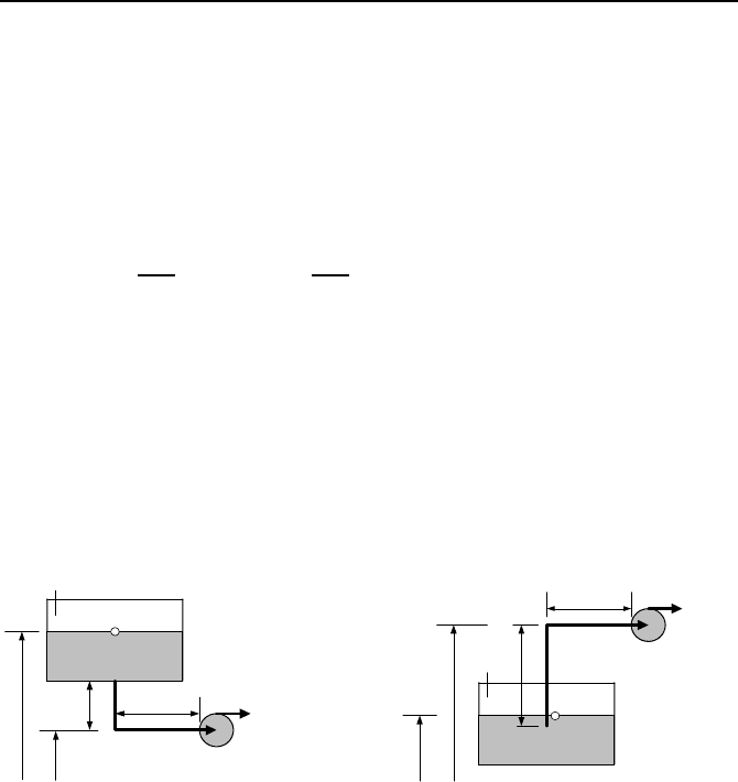
Example VIc.3.1. A performance curve of a typical centrifugal pump having an
impeller diameter of 41.5 inches at 710 rpm (pump A) is shown in the figure.
Find the performance curve of the homologous pump (pump B) having a head and
flow rate of 325 ft and 3000 GPM at the point of best efficiency.
756 VIc. Applications: Fundamentals of Turbomachines
200
220
240
260
280
300
320
340
0 5000 10000 15000 20000 25000 30000
Flow rate (GPM )
Head (feet)
D
= 41.5"
N
= 710 rp
m
60
65
70
75
80
85
90
0 5000 10000 15000 20000 25000 30000
Flow Rate (GPM)
Pump efficiency (%)
Solution: We use the conditions for dynamic similarity given by three relations in
Equation VIc.3.1. Since head and flow rate of pump B are specified at the point
of best efficiency, to satisfy the third condition, we also use the head and flow rate
of pump A in the first and the second relations at the point of best efficiency.
Flow rate and head for pump A at the point of best efficiency (i.e. at
η
≅ 88%)
are about
o
V
= 22000 GPM and H
o
= 270 ft, respectively. Hence, from
3
AA
A
3
BB
B
VV
DNDN
=
and
2
A
2
A
A
2
B
2
B
B
HH
DN
g
DN
g
=
we solve for D
B
and N
B
, to find
()
()
A
2/1
AB
4/1
BAB
V/VH/H DD
=
and
()
A
4/3
ABBAB
/HHV/V NN
=
.
Substituting for flow rates, heads, and D
A
, we get D
B
= 14.63 inches and N
B
=
2209 rpm. Having, D
B
and N
B,
other points of the pump B characteristic curve at
other efficiencies can be obtained by using similar points of pump A.
In the next example, we compare pump A of Example VIc.3.1 with another
pump, which belongs to the same homologous series of pumps (say pump C). Our
intention is to verify if the homologous pumps can be represented only with the
non-dimensional groups.
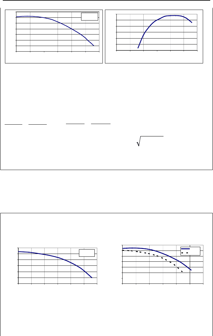
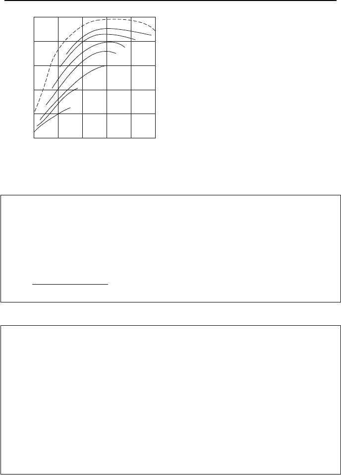
Example VIc.3.2. A performance curve of Pump C, which is homologous to
pump A of Example VIc.3.1, is shown below in the left-hand side plot. Find the
head versus the flow coefficient for these pumps.
400
450
500
550
600
650
700
0 5000 10000 15000 20000 25000 30000
Flow rate (GPM)
Head (ft)
D = 36.75"
N
= 1170 rpm
3.00
3.50
4.00
4.50
5.00
5.50
6.00
6.50
0 0.025 0.05 0.075 0.1 0.125 0.15
C
Q
C
H
Pump A
Pump C
Solution: Having N and D for each pump, as well as the characteristic curves (H
versus
V
) for both pumps A and C, we find the head and flow coefficients as
plotted in the right graph in the above figure. This figure shows that for geometri-
cally similar pumps, the head coefficient is almost a unique function of the capac-
ity coefficient. The reason for the slight difference is due to the assumptions we
3. Dimensionless Centrifugal Pump Performance 757
made namely, ignoring the viscosity effects and the surface roughness. Similar
comparison can be made for the brake horsepower coefficient and efficiency of
pumps A and C.
Even with ignoring the effects of viscosity and surface roughness to find the
two independent variables H and
BHP
W
, we need to know the values of three in-
dependent variables:
V
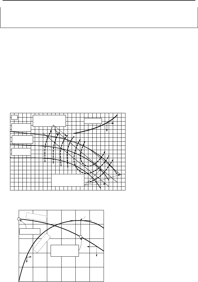
, N, and D. Shown in Figure VIc.3.1(a) are head and
brake horsepower (also efficiency and NPSH) versus flow rate for a specified di-
ameter and a specified impeller speed. These data, referred to as the pump charac-
teristic curves, are produced empirically by the pump manufacturer. Due to the
complexity of dealing with a multi-variable system, it is essential, especially for
computer analysis, to use single graphs to represent the pump characteristic
curves. Example VIc.3.1 showed that dimensionless homologous curves allow us
to make such single graph representations, as shown in Figure VIc.3.1(b).
NPSH
Lines of Constant
Efficiency
Lines of Constant
Brake Horsepower
D
3
> D
2
D
1
D
2
> D
1
H
N
V
.
(a)
C
V
.
C
H
η
Normal or Design
Flow Rate
Shutoff Head
H
e
a
d
E
f
f
i
c
i
e
n
c
y
BEP
(b)
Figure VIc.3.1. Representation of (a) pump characteristic curves by (b) homologous
curves
758 VIc. Applications: Fundamentals of Turbomachines
Example VIc.3.3. Use the similarity rules and compare the performance of a se-
ries of homologous pumps for various impeller diameters and impeller speeds.
Solution: The similarity rules require that;
,
V
V
3
1
2
1
2
1
2
¸
¸
¹
·
¨
¨
©
§
=
D
D
N
N
,
H
H
2
1
2
2
1
2
1
2
¸
¸
¹
·
¨
¨
©
§
¸
¸
¹
·
¨
¨
©
§
=
D
D
N
N
and
5
1
2
3
1
2
1
2
1
2
¸
¸
¹
·
¨
¨
©
§
¸
¸
¹
·
¨
¨
©
§
=
D
D
N
N
W
W
ρ
ρ
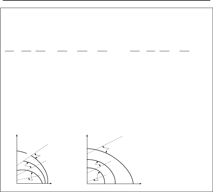
These relations indicate that brake horsepower varies significantly with impeller
size, as it depends on the diameter to the power of 5. The impeller size also af-
fects flow rate since for the same total dynamic head, we get higher flow rate with
higher diameter. Pump performance curves for various diameters and speed are
plotted on the comparative diagrams where D
1
< D
2
< D
3
and N
1
< N
2
< N
3
. Note
that the similarity rules require that we also have
η
1
=
η
2
. In reality however, lar-
ger pumps generally have higher efficiency than smaller pumps due to the
smoother surfaces and tighter clearances.
N = N
2
= Constant
D
1
D
2
D
3
H
V
W
BHP
.
.
D = D
2
= Constant
C
o
n
s
t
a
n
t
B
r
a
k
e
H
o
r
s
e
p
o
w
e
r
N
3
N
2
N
1
H
W
BHP
.
V
.
3.1. Specific Speed
In Example VIc.3.1, we eliminated the impeller diameter and obtained
B
N =
()
()
1/ 2
3/4
AB BA A
V/V H/H
N
. If we now assume that for pump B, 1V
B
=
GPM
and H
B
= 1 ft, then N
B
is known as specific speed of the pump (N
s
) given by:
3/4
o
1/2
o
H/V
NN
s
= VIc.3.2
Therefore, for a homologous series of pumps, the specific speed is the pump speed
that delivers a unit discharge at unit head at the BEP since N
s
is generally calcu-
lated at the point of peak efficiency (shown by subscript o). Specific speed ex-
pressed in the U.S. customary units is calculated assuming speed in RPM, flow
rate in GPM and head in feet. The advantage of specific speed is that it is associ-
ated with a particular range of values for each class of pumps. For example, high-
head and low-flow pumps have a specific speed in the range of about 500 in U.S.
customary units. As flow rate increases and dynamic head drops, the specific
speed increases. Wislicenus showed (Figure VIc.3.2) that pump peak efficiency
increases with increasing flow rate and specific speed.
3. Dimensionless Centrifugal Pump Performance 759
5 GPM
30
100
1000
10,000
10
∞
100 1000
300
3000 10,000
30,000
0
0.2
0.4
0.6
0.8
1.0
N
s
η
max
300
Figure VIc.3.2. Pump peak efficiency versus specific speed
Example VIc.3.4. Use the pump performance data of Example VIc.3.1 to find
specific speed.
Solution: Specific speed is found at the point of peak efficiency. Therefore,
given an impeller speed of 710 RPM, a flow rate of 22,000 GPM (8248 lit/s), and
head of 270 ft (82.3 m), we find:
1581
)270(
)000,22(710
75.0
5.0
=
×
=
s
N
Example VIc.3.5. Find the specific speed of a pump with flow rate of 50,000
GPM and head of 23 ft. For this pump the capacity coefficient and the head coef-
ficient at the BEP are 0.1 and 5.0, respectively.
Solution: Flow rate in ft
3
/s is 50,000 GPM × (1 ft
3
/7.481 gallon) × (1 min/60) =
111.4 ft
3
/s.
V
C =
3
/V ND
, therefore, ND
3
= V
/
V
C = 111.4/0.1 = 1114
C
H
= gH/N
2
D
2
, therefore, N
2
D
2
= gH/C
H
= 32.2 × 23/5 = 148.12
Solving for N and D, we find D = 9.6 ft and N = 1.3 revolution/s = 76 RPM. Since
high flow rate is pumped at a low head, the impeller diameter becomes too large
and the impeller speed too slow. The specific speed is found as N
s
=
76(50,000)
1/2
/(23)
3/4
= 1619.
The disadvantages associated with large diameter impeller and slow speed
pumps include size accommodation and cost associated with parts (bearings, shaft,
impeller, mechanical seals, and casing) in manufacturing and operation. As seen
from the above example, the centrifugal pumps are well suited for low flow and
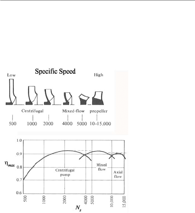
760 VIc. Applications: Fundamentals of Turbomachines
high head applications. Delivering high flow rates at lower head is better accom-
plished with pumps that reduce the radial component and increase the axial flow
component. Figure VIc.3.3 shows that the large diameter radial flow impeller
should be used for low specific speed. As specific speed increases, the shape of
the impeller changes to reduce the centrifugal component in favor of the axial
flow component. At very high specific speeds, pumps equipped with propeller
should be used.
Figure VIc.3.3. Depiction of type and efficiency versus specific speed (White)
3.2. Prevention of Pump Cavitation
The required NPSH to avoid cavitation (NPSH
R
) is specified by the pump manu-
facturer. As shown in Figure VIc.3.4, NPSH is a function of flow rate and impel-
ler speed. Installation of the pump must ensure that the available NPSH remains
always greater than the required NPSH. Therefore, to avoid cavitation, we must
ensure that NPSH
A
> NPSH
R
holds during pump operation. In fact, to enhance the
margin to the onset of cavitation, it is recommended (Kreith) to increase the
NPSH
R
by an additional 2 to 3 m (6.5 to 10 ft).
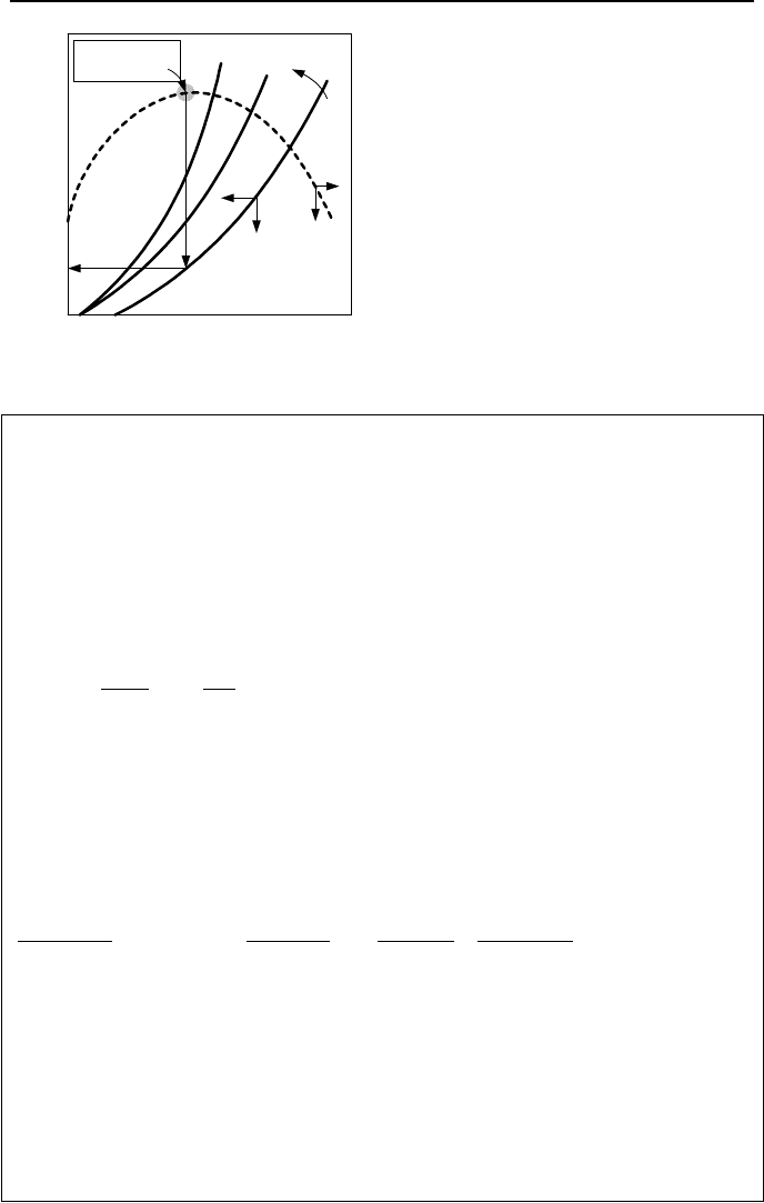
3. Dimensionless Centrifugal Pump Performance 761
N
1
N
2
N
3
η
NPSH
Point of Best
Efficiency
V
.
Figure VIc.3.4. Effect of flow rate and speed on the required NPSH
Example VIc.3.6. A centrifugal pump is used to deliver water at a rate of 250
GPM. The pump manufacturer has specified a minimum NPSH of 17 ft. The
source reservoir is open to the atmosphere. The suction piping has a diameter of
3.5 in. with a total loss coefficient of K = 8. Find the maximum height that the
pump can be placed above the reservoir to prevent cavitation. Water in the reser-
voir is at 14.7 psia and 75 F. The horizontal suction pipe run is 18 ft.
Solution: We use Equation VIc.2.1. Water is at P
i
= 14.7 psia, and 75 F. The
vapor pressure is about P
v
= 0.43 psia. Total head loss in the suction piping is:
g
V
D
s
f
fs
2
K
į
h
2
¸
¹
·
¨
©
§
+
+
=
where s is the height we are looking for and δ = 18 ft is the specified horizontal
pipe run to pump intake. To find velocity, we use V
= 250/(7.481 × 60) = 0.557
ft
3
/s and A = πD
2
/4 = 3.14 × (3.5/12)
2
/4 = 0.0668 ft
2
. Hence, V = 0.557/0.0668 =
8.34 ft/s and Re =
ρ
VD/
µ
= 62.4 × 8.34 × (3.5/12)/6.25E-4 = 0.243E6. Assuming
a smooth pipe, f = 0.184/Re
0.2
= 0.0154. Using Equation VIc.2.1:
17
4.62
14443.0
2.322
34.8
8
)12/5.3(
18
0154.0
4.62
1447.14
2
=≥
×
−
×
¸
¸
¹
·
¨
¨
©
§
+
+
−−
×
R
NPSH
s
s
From here s= Z
p
– Z
i
= 6 ft. Hence, Z
P
= Z
i
+ 6 ft. This is the maximum eleva-
tion for the pump to avoid cavitation. Note that in this example head loss due to
skin friction (h
1
= 1.4 ft) is by far smaller than losses due to valves, filters, and fit-
tings (h
2
= 8.64 ft) on the suction line. In general, the suction line must be located
as close to the source reservoir as possible with as few valves and fittings on the
suction line as absolutely necessary. Head loss due to skin friction can become
noticeable in cases where pumps cannot be located near the source reservoir with
only few fittings on the suction line.