Massoud M. Engineering Thermofluids: Thermodynamics, Fluid Mechanics, and Heat Transfer
Подождите немного. Документ загружается.

6. Power Producing Systems, Nuclear Power Plants 11
cussed in Chapter IIb, due to the high temperatures produced in the combustion
chamber, gas turbines operate at higher thermal efficiency, defined as the ratio of
power produced to the rate of energy consumed, compared with the efficiency of
reciprocal engines or steam power plants.
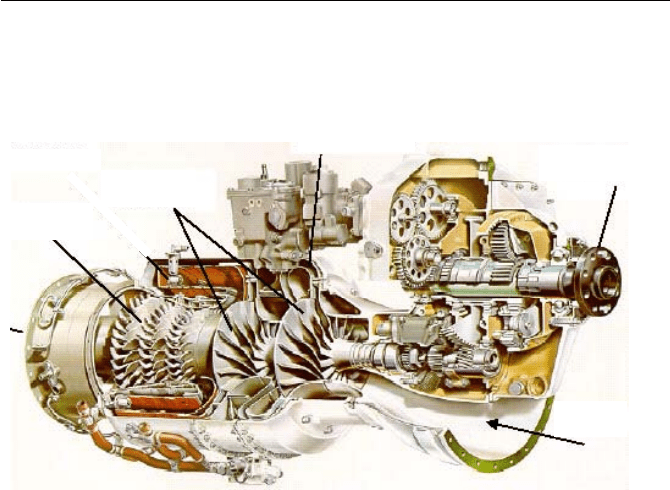
Radial
Compressors
Axial
Turbine
Intake
Drive Shaft
Figure I.5.6. A turboshaft engine using radial compressors and axial turbine
6. Power Producing Systems, Nuclear Power Plants
Nuclear power supplies about 17% of world’s electricity. In France, about 80% of
electricity is supplied by nuclear energy. In the United States, nuclear energy is
the second largest source of electricity, providing power for 65 million homes.
Unlike fossil fuels, nuclear energy does not produce any emissions to contribute to
the greenhouse effect and global warming. Indeed if nuclear plants were to be re-
placed by fossil plants, the CO
2
emission worldwide would increase by 21%
(Mayo). Schematics of two types of classic U.S. designed light water reactors are
shown in Figure I.6.1.
Traditionally, nuclear reactors are classified based on neutron energy and the
type of coolant/moderator. As mentioned in Section 3 and discussed in Chap-
ter VIe, high-energy neutrons are referred to as fast and low energy neutrons are
referred to as thermal neutrons. Reactors using high-energy neutrons for fission
are referred to as fast reactors. Most commercial reactors are of the thermal type.
Thermal reactors in addition to the coolant, as working fluid, also require modera-
tor to thermalize neutrons. In most cases however, the coolant also plays the role
of the moderator. There are generally three types of coolants used worldwide in
power producing nuclear reactors: water, liquid metal, and gases such as helium.
Water-cooled reactors are subdivided into light water (H
2
O) and heavy water
(D
2
O) reactors, which use deuterium, an isotope of hydrogen.

12 I. Introduction
All U.S. nuclear plants for power production are of the light water type being
either a PWR or a BWR. In BWRs water boils inside the reactor vessel at a pres-
sure of about 1050 psia (7.2 MPa), while in PWRs pressure is raised to about 2250
psia (15.5 MPa) to prevent water from boiling in the reactor. In PWRs, boiling
takes place in the secondary side of the steam generator.
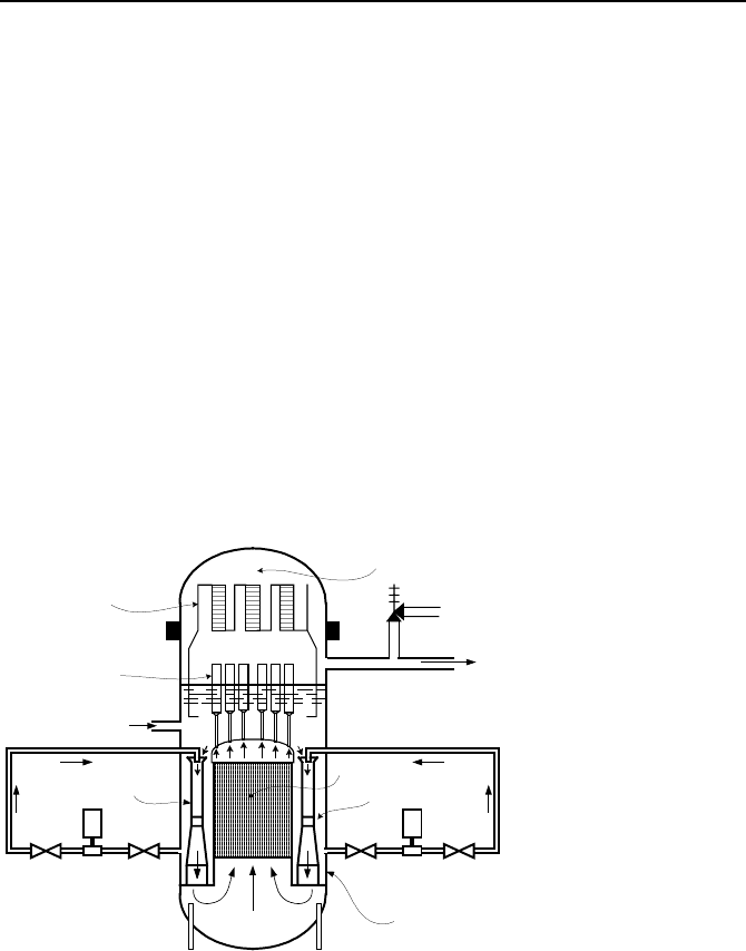
Reactor Pressure Vessel
Separator/Dryer
Core
Turbine
Condenser
Feedwater
Dry Steam
Containment
Condensate Pump
Heater
Extraction
Steam
Feedwater
Pump
Downcomer
Reactor Pressure Vessel
Core
Turbine
Condenser
Feedwater
Pump
Feedwater
Dry Steam
Heater
RCP
Pressurizer
Separator/ Dryer
Steam Generator
Containment
Surge Line
Steam
Extraction
Condensate Pump
Downcomer
Figure I.6.1. Schematics of a BWR (above) and a PWR (below) plant
Gas cooled reactors (GCR) and advanced gas cooled reactors (AGR) use he-
lium as the working fluid to reach high temperatures. GCRs are mostly used in
England. For these types of reactors large compressors are required to circulate
the coolant. Finally, a liquid metal fast breeder reactor (LMFBR) uses sodium as
coolant.
6. Power Producing Systems, Nuclear Power Plants 13
6.1. Boiling Water Reactor
Since water boils in the core of a BWR, these types of reactors are known as di-
rect-cycle power plants. The mixture of water and steam leaves the reactor core
and enters the separator-dryer assembly to separate moisture from steam. As dis-
cussed in Chapter IIb, it is essential to deliver dry steam to the turbine. While dry
steam enters the steam line and flows towards the turbine, the separated water at a
temperature of about 550 F (288 C) flows downward towards the downcomer re-
gion of the reactor pressure vessel (RPV). The downcomer is an annulus between
the RPV wall and the core barrel. The feedwater flow, delivered to the RPV by
the main feedwater pumps also enters the downcomer but at about 375 F (190 C).
These streams must mix well prior to entering the core. This task in the traditional
BWR (designed by General Electric) is accomplished by two recirculation loops,
each consisting of a recirculation pump, piping, and valves as shown in Fig-
ure I.6.2. The recirculation pumps withdraw water from the lower portion of the
downcomer region and deliver to the inlet of up to 20 jet pumps. Jet pumps are
made of stainless steel and consist of a suction inlet, throat (mixing section), and a
diffuser. For plants operating at 1000 psia (7.2 MPa), the recirculation flow at a
temperature of 545 F (285 C) then enters the lower plenum region of the RPV.
Main Steam Line
Safety Relie
f
Valves
Main Feedwater
Recirculation
Pump
Core
Jet Pump
Steam Separators
SteamDryers
Steam Dome
Lower Plenum
Reactor
Pressure Vessel
Downcomer
Figure I.6.2. A BWR reactor vessel
In the advanced BWR plants (ABWR, designed by Toshiba), the recirculation
loops are eliminated. The recirculation in these plants takes place inside the RPV.
Thus, the recirculation pumps and the jet pumps are combined and replaced by up
to 10 internal pumps equipped with a motor (placed outside the RPV) and an im-
peller for forced mixing (placed in the downcomer). The recirculation pumps in
BWRs and the reactor internal pumps in ABWRs play an important role in con-
trolling the reactor power.

14 I. Introduction
The well-mixed coolant entering the lower plenum flows upward into the core
to remove heat from nuclear fission taking place in the fuel rods. The fuel rods
are placed in square arrays of 8 × 8, 9 × 9, or 10 × 10 in a rectangular parallelepi-
ped metal container referred to as fuel assembly or fuel bundle. The number of
fuel bundles depends on the reactor power and may range from about 550 (for
800 MWe plants) to 870 (for 1350 MWe plants). Coolant, which at the core exit
is a mixture of steam and water, leaves the fuel bundles and enters the upper ple-
num. From the upper plenum, coolant enters standpipes and is directed into the
steam separator and steam dryer, as discussed earlier. The steam line leading to
the turbine is equipped with safety and relief valves (SRV) as well as a main
steam isolation valve (MSIV).
6.2. Pressurized Water Reactor
Unlike BWRs, no bulk boiling occurs in the core of a PWR; rather, boiling takes
place in the secondary side of the steam generator (SG). Due to the presence of
steam generators, PWRs are not direct-cycle power plants as they consist of a pri-
mary side and a secondary side. There is no mixing between the fluids flowing in
each side, heat is transferred through the steam generator tube wall from the pri-
mary- to the secondary side. To prevent coolant from boiling in the primary side,
pressure in a PWR vessel is more than twice that of a BWR (about 2250 psia, 15.5
MPa). Also, unlike BWRs, PWRs have an open core where flow can also move
laterally between the fuel assemblies. There are generally over 200 fuel assem-
blies in the core of a PWR, each consisting of a square array of 15 × 15 fuel rods.
The operating PWRs in the U.S. are of three designs: W (Westinghouse), CE
(Combustion Engineering), and B&W (Babcock & Wilcox)
3
. The major differ-
ences are in the number and the type of the steam generators, as shown in Fig-
ure I.6.3.
The piping connecting the reactor vessel to the steam generator is referred to as
legs. Pipes carrying water from the SG to the reactor vessel and from the reactor
vessel to the SG are known as Cold Leg and Hot Leg, respectively. A pressure
and inventory control tank, known as the Pressurizer, is connected to the hot leg
through a surge line. The reactor coolant pumps (RCP) in the primary side of a
PWR plant are located on the cold leg.
Shown in Figure I.6.4 is a two-loop PWR power plant. As seen in this figure,
the outlet plenum of the steam generators is located on the suction of the reactor
coolant pumps, delivering water through the cold leg to the downcomer region of
the reactor vessel. Water then enters the lower plenum and flows to the core. De-
tails of the reactor vessel are shown in Figure I.6.5(a). A small fraction of the
coolant bypasses the core to cool the control rods. Water entering the core is at a
temperature of about 550 F (288 C) and water leaving the core is about 600 F
(316 C). The region on top of the core is referred to as the core outlet plenum.
Water entering the outlet plenum from the core then flows towards the upper in-
3
CE is now owned by BNFL (Westinghouse) and B&W by Framatome ANP.
6. Power Producing Systems, Nuclear Power Plants 15
ternals of the upper guide structure (UGS) and leaves the vessel through the hot
leg to the inlet plenum of the steam generator. In the steam generator primary
side, water from the inlet plenum moves upward toward the tubesheet and into the
U-tubes. Hot water exchanges heat with the colder water in the secondary side,
through the steam generator tube wall, and enters the outlet plenum of the steam
generator to be pumped back to the reactor vessel.
Details of the secondary side of a U-tube steam generator are shown in Fig-
ure I.6.5(b). In the secondary side, the main feedwater pump delivers water to the
downcomer at a relatively cold temperature of about 430 F (221 C). The colder
feedwater is then mixed with the warmer water, which is at a temperature on the
order of 530 F (277 C) and flowing downward from the separator-dryer assembly
of the steam generator. The mixed stream flows downward toward the tubesheet
and then upward when entering the tube bundle. The heat of the water transferred
through the tube causes this mixed stream to boil. The two-phase mixture eventu-
ally leaves the top of the U-tubes and wet steam enters the separator assembly.
Swirling vanes are installed in these assemblies to separate the entrained water
droplets by centrifugal force. Steam then enters the dryer assembly to further re-
duce the moisture content. The dry steam then leaves the dryer assembly and en-
ters the steam line to flow to the high-pressure stage of a steam turbine.
Similar to the BWR plants, the main steam lines in the PWR plants, connecting
the steam generator to the turbine, are equipped with a series of valves including
SRV, a steam dump valve, and a MSIV.
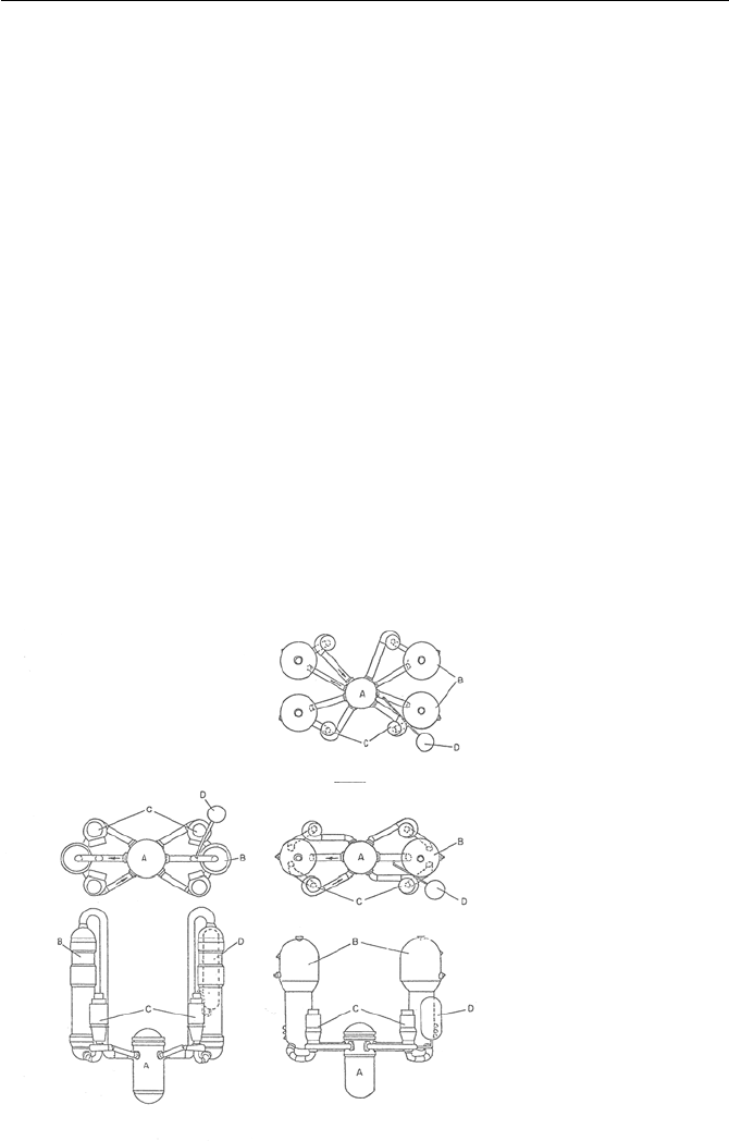
Plan of a 4-Loop Reactor
with U-tube SG (W)
A: Reactor Vessel
B: Steam Generator (SG)
C: Primary Coolant Pump
D: Pressurizer
Plan & Elevation of a 2-Loop
Reactor with U-tube SG (CE)
Plan & Elevation of a 2-Loop Reactor
with Once-Through SG (B&W)
Figure I.6.3. Various classic U.S. designs of the operating PWRs (Todreas)
16 I. Introduction
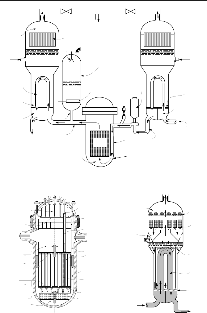
Reactor
Core
Pressurizer
Steam Generator
(SG)
Reactor Coolamt
Pump (RCP)
From Hot leg
Cold Leg
Hot Leg
To Cold Leg
U-Tubes
(Primary Side)
SG Outlet
Plenum
SG Inlet
Plenum
Tube Bundle
(Secondary-Side)
SG Steam
Dome
SG Separator &
Dryer Assembly
Steam Generator
(SG)
Main Steam Line
Main
Feedwater
Upper
Head
Reactor Pressure Vessel
(RPV)
Downcomer
Upper
ECCS
Lower Plenum
Plenum
Tubesheet
Heater
Spray
Safety & Relief Valve
To High-Pressure Turbine
Isolation Valve
Flow Restrictor
Surge
Line
Figure I.6.4. Schematic of the RCS of a pressurized water reactor, using U-tube steam
generators
Upper Guide
Structure
Core Barrel
Fuel Assembly
Core Support
Assembly
Flow Skirt
Downcomer
Core
Length
From
Cold Leg
To Hot Leg
Lower Plenum
Upper Plenum
Upper Head
Control
Assembly
Reactor Pressure
Vessel
In-Core
Instrumentation
Assembly
Fuel Rod
Fuel
Alignment
Plate
Core
Support
Plate
Control Rod
Drive Mechanism
Steam Dome
Steam
Separator
Wet Steam
Dry Steam
Feedwater
Recirculation
Downcomer
From Hot Leg
Tubesheet
Active tubes
Steam Dryer
To Cold Leg
(a) (b)
Figure I.6.5. Details of a PWR vessel (a) a PWR U-tube steam generator (b)
7. Power Producing Systems, Greenpower Plants 17
Fuel rods are thin hollow cylinders that are filled with uranium dioxide (UO
2
)
pellets. The hollow cylinder is referred to as cladding. The cladding material de-
pends on the type of the nuclear reactor. In a LMFBR, the cladding is made of
stainless steel while in LWRs, the cladding is generally made of an alloy of zirco-
nium, known as zircaloy. The small gap between the fuel pellets and the inside of
the cladding is filled with helium. During operation the fission gases that are re-
leased from the pellet also enter the gap region.
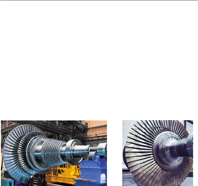
Steam turbines are the power producing machines of systems using a thermo-
dynamic cycle. The shaft of a steam turbine turns the rotor of the electric genera-
tor. Steam turbines are also used as prime movers to power pumps. The station-
ary blades in the casing of steam turbine act as diffuser in directing the incoming
steam to the blades of the rotor. As hot, energetic steam transfers its energy to the
rotor, the diameter of the rotor increases to maintain the rate of momentum trans-
fer. Figure I.6.6 shows the combined medium and low-pressure rotor and the dou-
ble-flow low pressure rotor of a steam turbine
Figure I.6.6. Steam turbine rotor (courtesy Siemens AG)
7. Power Producing Systems, Greenpower Plants
The so-called greenpower or renewable energy sources consist of a wide range of
sources including hydro, solar, geothermal, wind, and tidal. These sources of en-
ergy are briefly discussed next.
7.1. Hydropower Plants
After wood, falling water is the oldest source of energy. Romans used water
wheels, to harness power. The first U.S. hydropower plant, built on the Fox River
near Appleton, Wisconsin, generated electricity in 1882.
Figure I.7.1 shows the schematic of a hydropower plant including the turbine
generator. The lake water, referred to as the head water, flows through a conduit
known as the penstock towards the turbine. After turning the turbine runner, wa-
ter flows in the draft tube to become the tail water to flow in the river, downstream
of the turbine. As described in Chapter VIc, the turbine runner may be of Kaplan,

18 I. Introduction
Francis, or Pelton type, which then turns the shaft of the electric generator.
Shown in Table I.7.1 are the top 16 hydroelectric plants with respect to power
production. By the late 20
th
century, hydroelectric produced about 25% of the
global electricity and 5% of the total world energy, about 2,044 billion kilowatt-
hours. The disadvantage of hydropower plants includes a large initial investment
and a need for large bodies of water, with adverse effect on the river’s ecological
system and susceptibility to unfavorable weather conditions such as drought. Hy-
dropower plants can be classified in terms of water flow rate and the difference
between the elevations of water surface and the turbine. As discussed in Chap-
ter III, this height is referred to as Head.
Gener at or
Penstock
Draft Tube
(Tail Water)
Dam
H
Lake
(Head Water)
Turbine
Figure I.7.1. Schematic of a hydropower plant to convert potential energy to electric power
Table I.7.1. Power output (MWe) of the world’s largest hydropower plants
Name of Dam Location Present Ultimate Year operational
Itaipu Brazil/Paraguay 12,600 14,000 1983
Guri Venezuela 10,000 10,000 1941
Grand Coulee U.S.A. 6,494 6,494 1967
Sayano-Shushensk Russia 6,400 6,400 1989
Krasnoyarsk Russia 6,000 6,096 1968
Churchill Falls Canada 5,428 5,428 1971
La Grande 2 Canada 5,328 5,328 1979
Bratsk Russia 4,500 4,600 1961
Moxoto Brazil 4,328 4,328 1974
Ust-Ilim Russia 4,320 4,320 1977
Volga Russia 2,543 2,560 1958
Niagara U.S.A. 2,190 2,400 1961
Volga Russia 2,100 2,300 1955
Aswan Egypt 1,750 2,100 1967
Chief Joseph U.S.A. 1,024 1,950 1961
St. Lawrence Canada – U.S.A. 1,880 1,880 1958
The Three Gorges Dam in China, 60 stories high and 2.3 kilometer long, will be the world
largest dam. Upon completion in 2009, its 26 turbines will generate 18,200 MW electricity.

7. Power Producing Systems, Greenpower Plants 19
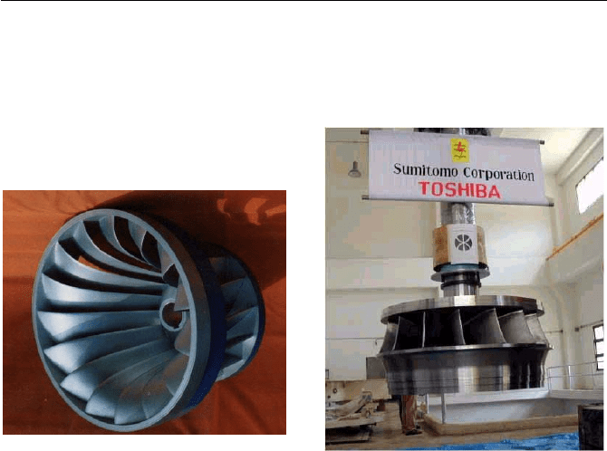
Low head and high flow rate are characteristics of rivers. For such condition,
water is directed towards the turbine rotors known as the axial-flow turbines or
Kaplan rotor. In this type, water flows between the vanes of the propeller and
imparts its momentum to the rotor, which in turn is connected to the electric gen-
erator shaft. Figure I.7.2 shows an axial flow rotor.
Figure I.7.2. Rotors of axial flow, Kaplan turbine (courtesy Toshiba Corporation)
High head and low flow are characteristics of water reservoirs on a mountain-
top. The turbine used to harness the water power in such cases is generally of the
impulse type using the Pelton wheel named after Lester Allen Pelton, who pat-
ented his wheel in 1889. As shown in Figure I.7.3, the Pelton wheel consists of
buckets attached to the perimeter of a rotating wheel. Depending on the site, the
wheel may be attached to a horizontal shaft or may be rotating horizontally con-
nected to a vertical shaft. In this type of turbine, water is directed into injectors so
that a jet of water strikes the bucket at high speed to turn the wheel. There may be
one or as many as six injectors directing water towards the buckets of the wheel.
The speed of the jet of water may reach values as high as 560 ft/s (171 m/s). A
needle valve throttles the flow in the injectors. The wheel is placed in a casing for
safety and to prevent water splashing. The principles of impulse turbines using
the Pelton wheel are discussed in Chapter VIc.
Figure I.7.3. Pelton wheels of impulse turbines
20 I. Introduction
Medium head, turbines are also of reaction type. Such turbines use the Francis
runner, as shown in Figure I.7.4. Water enters from the side, flows between the
vanes of the runner, and exits through the center.
Figure I.7.4. Runners of radial flow turbines, Francis turbine (courtesy Toshiba Corpora-
tion.)
7.2. Solar Power Plants
Solar energy, in the form of electromagnetic radiation that reaches the earth, by far
surpasses all other sources of energy in magnitude. However, large scale power
production by direct conversion of solar radiation to electricity by photovoltaic is
still in the research and development stage. Solar collectors are now used as a
residential heat source and for commercial applications such as space heating, and
to a lesser extent for the generation of electricity. Large-scale power production
by the use of solar collectors presently requires acres of land covered by special
reflectors to divert the sun’s ray to a central receiver, acting as a heat source.
Shown in Figure I.7.5 is the schematic of a thermal system for space heating
using solar energy. Water is circulated in a closed flow loop. The heat source for
this loop is the solar collector, heating water through the tube wall, which carries
the circulating water. The heat sink is a water storage tank, which is also heated
by an auxiliary heat source in cloudy weather and at night. The heat sink for the
solar loop acts as a heat source for the space being heated, as the tank water is cir-
culated in a heating coil over which the colder air flows.