Martin P.M. Handbook of Deposition Technologies for Films and Coatings, Third Edition: Science, Applications and Technology
Подождите немного. Документ загружается.

Characterization of Thin Films and Coatings 821
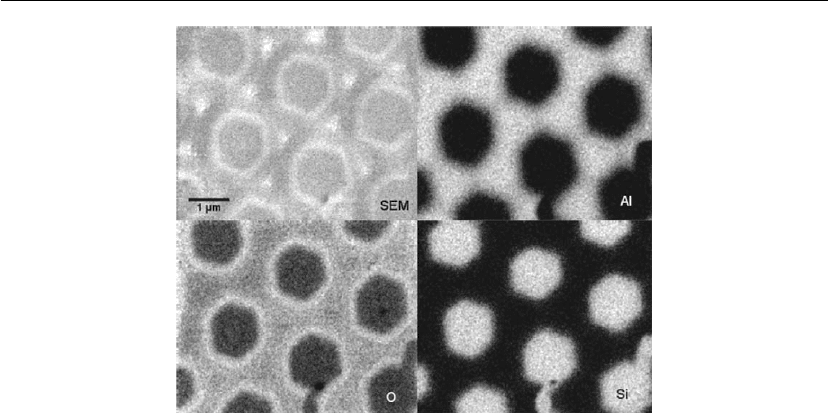
Figure 16.46: AES elemental map of Al patterned onto a Si substrate. This figure highlights the
distribution and relative intensities of the elements one can obtain using this technique.
where I
i
is the transition-specific peak-to-peak intensity of element i in the derivative
spectrum, and RSF
i
is the transition-specific relative sensitivity factor for element i. The
relative sensitivity factors are either obtained from published data [129, 130] or experimentally
determined by the operator using a well-defined set of standards. Equation (16.7) is a relatively
simple version of a more complex equation that does not take into consideration the instrument
transmission function (sensitivity dependence of the analyzer on the kinetic energy of the
electron being detected). It provides an estimate of the actual concentration of the species in
the sample. The reader is referred to previous work [131] that describes the methods needed to
determine the instrument transmission function required for accurate quantification.
Similar to XPS, the sensitivity of AES is element specific; however, in general, AES has lower
sensitivity than XPS. This lower sensitivity is due to the large background upon which the
Auger peaks reside. In order to remove the background and provide quantitative information,
the spectra are smoothed and differentiated, but this decreases the signal-to-noise ratio. The
sensitivity one can obtain using AES ranges from about 0.1 to 5 at.% depending on element,
data acquisition time, and the presence of interfering peaks.
Newer generation AES equipment has the capability to produce 2D maps of elemental
distribution on the sample surface. By moving the tightly focused electron beam in a raster
pattern across the surface and obtaining peak and background intensities for each element of
interest, a high-resolution, location-specific distribution of the elements can be generated and
correlated to an SEM image of the same location. Figure 16.46 shows one such elemental map
for Al patterned onto a Si substrate. This capability is extremely valuable for identifying

822 Chapter 16
regions of enrichment or depletion or for samples with an inhomogeneous distribution of
elements.
Instruments equipped with ion guns have the capacity to acquire depth-specific concentration
profiles. To generate these depth profiles, high-energy ions (typically Ar or O
2
) impinging on
the sample remove material from the sample surface, producing a sputter crater. By alternating
this ion sputtering with Auger electron analysis at the center of the sputter crater, one can
obtain depth-specific information about the presence of elements and their abundance. It is
necessary, however, to calibrate the rate of material removal in the sputtering process to get
accurate depth calibration. This is typically done using standards of known thickness (such as
thermally oxidized SiO
2
on a silicon wafer), although it should be pointed out that different
materials have different, though not too dissimilar, sputter rates.
While AES provides quantitative information about the concentration and distribution of
elements on the surface of the sample with high resolution and is useful for analysis of
nanoscale materials with little sample preparation, there are some limitations to the technique
that should be mentioned here. Foremost, since this technique utilizes highly energetic
electrons as the primary beam and generates backscattered primary, secondary, and Auger
electrons, any sample that is not conducting (or at least semi-conducting) is subject to charge
accumulation. This accumulation of charge at or near the sample surface may either shift the
characteristic energy of electrons leaving the surface (either slightly or dramatically) and/or
change the energy and position of the incident electron beam, which in many cases does not
allow one to obtain valuable Auger spectra [132]. Small insulating particles or films generally
can be analyzed, but bulk, insulating materials with high resistivity can be problematic. There
are procedures in place to lessen this charging effect (such as sample masking, sample tilting,
changing primary beam energy, using low-energy ions) [133], but in some cases even these
methods are inadequate and utilization of other surface analysis techniques is advised. In
addition, electrons have a short IMFP and readily impart some of their energy to neighboring
atoms as they propagate through the sample. This can result in damage to the sample,
particularly for organic materials, through a number of mechanisms including bond scission,
desorption, and sample heating [25]. This can become problematic if the sample changes its
composition on the time-scale that is necessary to perform the analysis or if subsequent
analyses using a different technique are to be performed.
Strengths:
Highest spatial resolution surface analysis instrument.
Quantitative elemental concentrations.
All elements other than H and He can be detected.
Surface sensitive.
Characterization of Thin Films and Coatings 823
Elemental mapping.
Depth profiles.
Limitations:
Charging of bulk insulating materials can prevent EDS and EBSD analysis.
Limited ability to obtain chemical information.
Electron beam can damage sensitive materials.
High background due to inelastic electron scattering.
16.5.2 Scanning Electron Microscopy
B.W. Arey
A scanning electron microscope images the topography and structure of a sample by collecting
secondary or backscattered electrons created by scanning the sample with a focused electron
beam, the energy ranges from 100 eV to 30 keV. The resulting images can be collected at very
high magnification to provide a great deal of information about surface topography. The
incident beam also excites characteristic X-rays which can be used to collect elemental
information about the sample using energy or wavelength dispersive X-ray detectors.
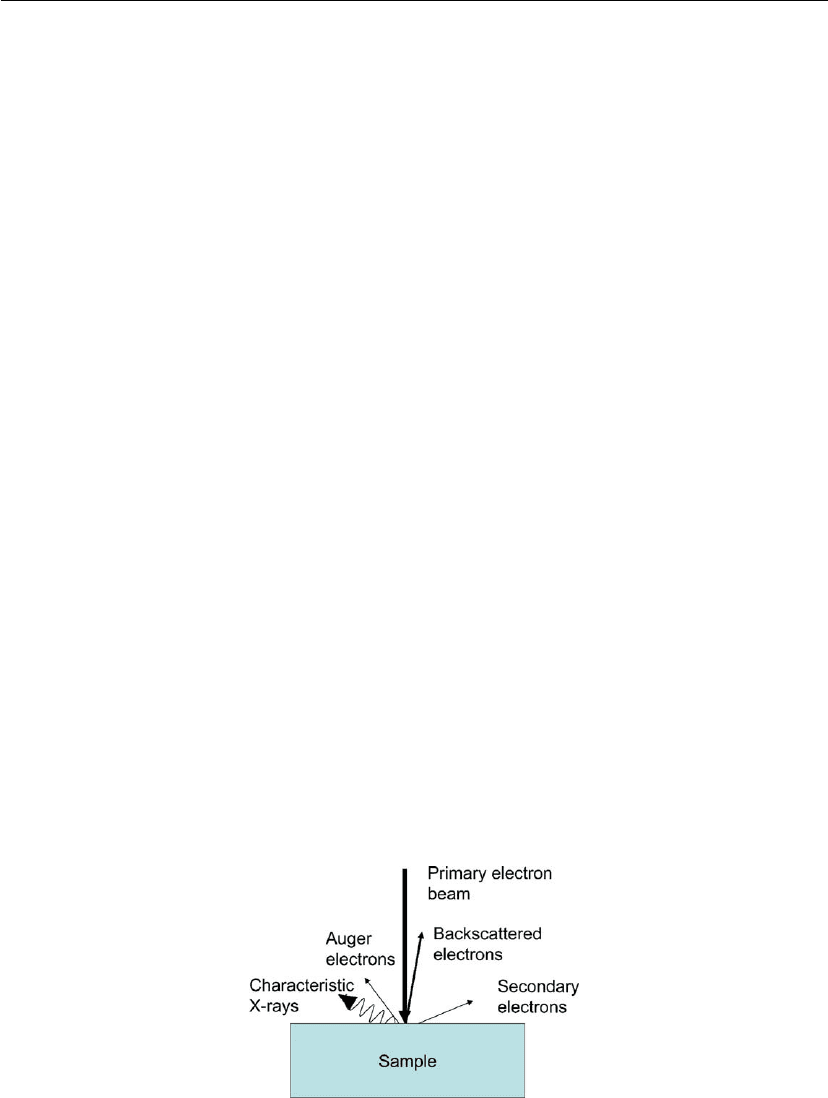
When an electron strikes the surface some electrons are backscattered (and have energies
similar to the incident beam), some lower energy secondary electrons are excited (< 50 eV), a
few Auger electrons are produced (Section 16.5.1), and characteristic X-rays are excited
(Figure 16.47). Using different types of detectors each of these types of electrons or photons
can be used to create images or determine other information about samples. A simplified
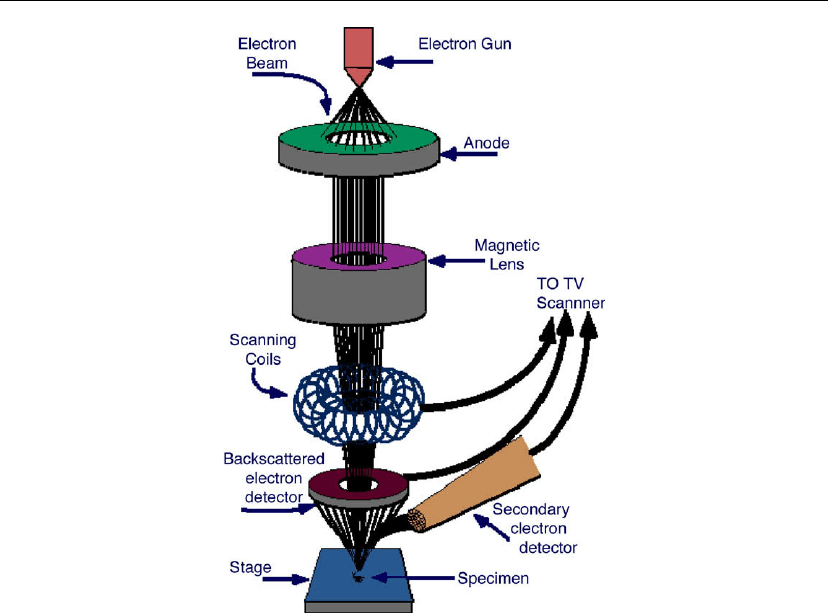
drawing showing components of a scanning electron microscope is shown in Figure 16.48.
Secondary electron imaging shows the topography of surface features a few nm across. Films
and stains as thin as 2 nm produce images with adequate contrast. Materials are viewed at
Figure 16.47: Schematic drawing showing types of electrons and photons produced when an
electron beam interacts with a solid sample.
824 Chapter 16
Figure 16.48: Schematic of SEM components. Note that there are detectors for secondary
electrons (< 50 eV) and for elastically backscattered electrons which have energies approximately
equal to the incident electrons. Other detectors can be added for X-rays or Auger electrons. (With
permission from Prof. S. Chumbley, http://mse.iastate.edu\microscopy\path2.html.)
useful magnifications up to 800,000× without the need for extensive sample preparation and
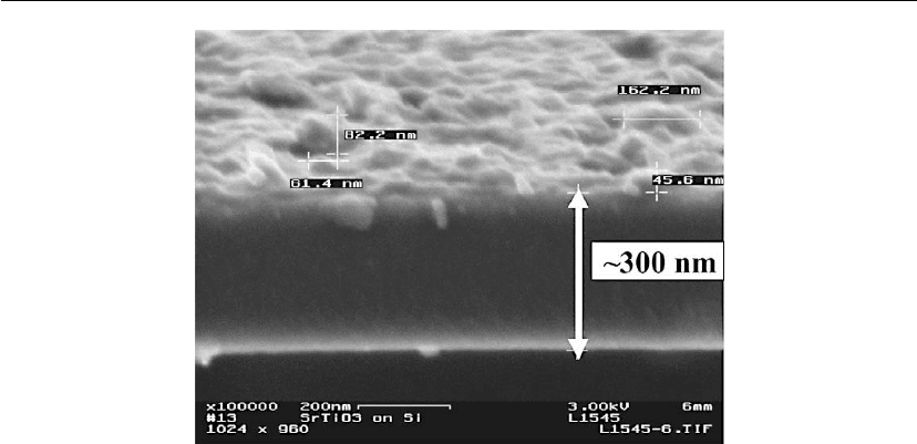
without damaging the sample. Thickness of thin films can be determined using SEM
micrographs. As an example, we used SEM to determine the thickness of an ion beam sliced
SrTiO
3
film. In this work we used 40 keV H
+
ions followed by subsequent annealing [134].
The SEM micrograph of this film is shown in Figure 16.49.
Backscattered electron imaging highlights the spatial distribution of elements or
compounds with different atomic number within the top micrometer of the sample. Features
as small as 10 nm are resolved and composition variations of as little as 0.2% can be
measured.
EDXS can be used to identify the elemental composition of materials imaged in a scanning
electron microscope for all elements with an atomic number greater than boron. Most elements
are detected at concentrations on the order of 0.1%. As the electron beam of the SEM is
scanned across the sample surface, it generates X-ray fluorescence from the atoms in its path.
Characterization of Thin Films and Coatings 825
Figure 16.49: SEM micrograph of H
+
irradiated and 570 K annealed SrTiO
3
[134].
The energy of each X-ray photon is characteristic of the element that produced it. The EDXS
microanalysis system collects the X-rays, sorts and plots them by energy, and automatically
identifies and labels the elements responsible for the peaks in this energy distribution. The
drawback of using EDXS on thin films is the interaction volume, the amount of material
excited by the incident electrons, which extends from all of the volume of the film material and
well into the substrate. Although the electron beam size may be as small as several nm, the
diameter of material excited is proportional to the depth of the material excited, which can be a
micrometer or so, depending on the energy. To reduce this, one can reduce the accelerating
voltage or tilt the sample. There will be some interaction with bulk material but the effect can
be minimized.
EBSD is a technique which allows crystallographic information to be obtained from samples
in the scanning electron microscope. In EBSD a stationary electron beam strikes a tilted
crystalline sample and the diffracted electrons form a pattern on a fluorescent screen. This
pattern is characteristic of the crystal structure and orientation of the sample region from
which it was generated. The diffraction pattern can be used to measure the crystal orientation,
measure grain boundary misorientations, discriminate between different materials, and provide
information about local crystalline perfection. When the beam is scanned in a grid across a
polycrystalline sample and the crystal orientation measured at each point, the resulting map
will reveal the constituent grain morphology, orientations, and boundaries. These data can also
be used to show the preferred crystal orientations (texture) present in the material. A complete
and quantitative representation of the sample microstructure can be established with EBSD. In
the past 10 years EBSD has become a well-established technique for the scanning electron

826 Chapter 16
microscope, and obtaining crystallographic information from samples is now both routine and
easy.
Strengths:
Electron imaging of microstructures.
Elemental analysis and mapping.
Electron backscattering for heavy element analysis.
Limitations:
Requires vacuum.
Bulk sensitive.
Electron beam can damage the sample.
High background due to Bremsstrahlung irradiation.
EDXS analysis is semi-quantitative.
16.5.3 Methods Related to Transmission Electron Microscopy
(TEM, AEM, HRTEM, STEM, EELS)
C.M. Wang
Although TEM can be viewed as a high-resolution imaging tool that uses electrons as an
illumination source [135–141], electron microscopes are multitechnique instruments that can
provide a wide variety of information about thin films and many other types of specimens. The
information may include sample morphology, structure, grain size, chemical composition, and
composition distribution. Based on diffraction limit, the imaging resolution, as a rule of
thumb, equals approximately half of the wavelength of the illumination light. Electron beam
accelerated by 200 kV potential corresponds to a wavelength of ∼0.0025 nm. Consequently,
TEM will provide much higher imaging resolution than an optical microscope. It should be
noted that image resolution is not at the theoretical limit because of lens aberrations, as
illustrated below.
In a very simple terms, a transmission electron microscope is structured much like an optical
microscope, consisting of four essential parts: (1) an electron gun, which generates and
accelerates the electron beam (light source); (2) a condenser lens, which manipulates the
electron beam from the electron gun; (3) an objective lens, which is the first lens to take over
the information following the interaction of the electron beam with the thin section of the
specimen; and (4) an image recording system, such as an image plate and CCD. Since the
invention or demonstration of the first functioning transmission electron microscope by Ernst
von Ruska and his colleagues in Berlin around 1934 [142], TEM has gone through a
Characterization of Thin Films and Coatings 827
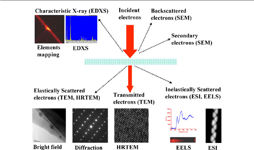
Figure 16.50: Schematic drawing showing the interaction of electrons with a thin section of
specimen and the signals that are used either for formation of image or spectroscopy.
tremendous evolution in both the instrumentation and imaging modes based on the physics of
the interaction of electrons with the specimen. At least in part, the different development paths
account for the many terminologies that are applied to different aspects of TEM. For example,
if the chemical composition analysis capability is emphasized, the technique is termed
analytical electron microscopy (AEM). If the diffraction contrast and low magnification
imaging capability are emphasized, it is normally termed conventional transmission electron
microscopy (CTEM). If the phase contrast and lattice structural image are emphasized, it is
normally termed high-resolution transmission electron microscopy (HRTEM). If a focused
beam is scanned over the specimen, this is known as scanning transmission electron
microscopy (STEM). If the signals related to inelastic electron scattering process are collected,
this leads to the techniques of energy-dispersive X-ray spectroscopy (EDXS) and electron
energy-loss spectroscopy (EELS). Generally speaking, the terminology is associated with how
the electron source/beam is generated, how the electron beam is manipulated, and/or what kind
of signal is collected following the interaction of the electron beam with the specimen. The
interactions of the electron beam and the signals that relate to each of these terminologies are
summarized in Figure 16.50.
Electron sources can be generally divided into three types: (1) the thermionic gun, which relies
on heating up of a filament to reddish-hot to obtain electrons; therefore the electrons have a
typical energy spread of ∼1.5 eV; (2) the cold field emission gun, which is based on applying
a strong electric field to a filament tip to extract electrons; this kind of source typically yields

828 Chapter 16
electrons with an energy spread of ∼0.3 eV; and (3) the Schottky field emission gun, which is
a thermally assisted field emission gun and yields electrons with energy spread of typically
∼0.8 eV. Among these three types of electron guns, the Schottky field emission gun normally
has the highest brightness and is widely used in modern TEM as well as SEM. The electrons
from the electron gun are accelerated with a potential typically in the range of 80–300 kV (for
some special microscopes it has an acceleration voltage of 400 kV and 1200 kV) in the lens
columns.
The condenser lens in a microscope is normally composed of several electromagnetic lenses
and the essential role of the condenser lenses is to allow the operator to control electron beam
characteristics such as beam diameter/size, convergence angle of the beam, and current density
of the electron beam. One of the important and challenging aspects associated with TEM is the
specimen, which must be thin enough to allow the transmission of the electron beam with an
acceleration voltage ranging from 80 to 400 kV. A typical thickness of a TEM specimen can
range from several nanometers to ∼1000 nm. Methods to make such thin material sections for
TEM are a field of art, science, and technology which will be briefly described in the
subsequent paragraphs.
With a stationary ray of electron beam impacting a thin section of specimen, a significant
portion of the electron beam will transmit through the thin section of the specimen. When an
objective lens focuses the electrons emerging from the bottom surface of the sample, the
images can be magnified. This occurs for TEM, CTEM, and HRTEM imaging and is
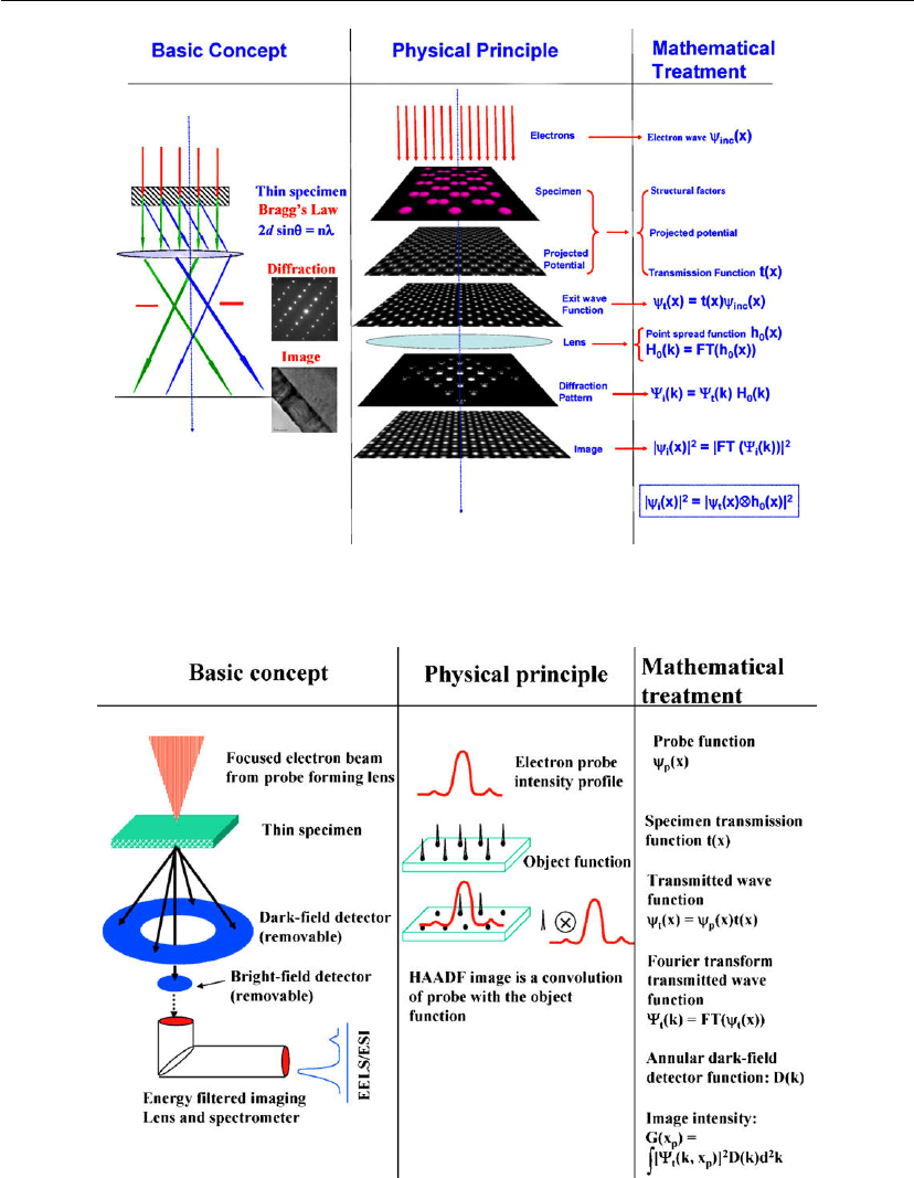
schematically illustrated in Figure 16.51. The figure illustrates the basic concepts, the physics,
and the mathematical treatment on the formation of the image in HRTEM. As with any kind of
imaging tool some type of contrast is needed to generate an image. In this imaging
configuration there are three types of contrast mechanisms: (1) mass thickness contrast
originates from the differences in the scattering of electrons by the nuclei of the elements. This
contrast mechanism leads to a high Z element appear darker than a low Z element in the bright
field (BF) image if they have the same sample thickness; (2) diffraction contrast is controlled
by the crystal structure and orientation of the crystal with respect to the electron beam. This
mechanism is conveniently controlled by the use of objective aperture at the back focal plane
of the objective lens. If the transmitted beam is used to form the image, this is called the BF
image. If only a diffraction beam is selected to form the image, it is called the dark field (DF)
image; (3) phase contrast arises whenever more than two beams are used to form the image.
An HRTEM image is a typical phase-contrast image.
During STEM imaging, a focused electron beam is scanned point by point over a thin section
of the specimen and electrons transmitted through the specimen are collected. The basic
concepts, physical principles, and mathematical treatments of the STEM imaging are shown in
Figure 16.52. If the directly transmitted beam is collected, it is called a STEM-BF image. If
electrons scattered to higher angles are collected, it is called a STEM-HAADF image (where
Characterization of Thin Films and Coatings 829
Figure 16.51: Schematic drawing showing the basic concept, physical principle, and the
mathematical treatment of the formation of an HRTEM image. FT: Fourier transform.
Figure 16.52: Schematic drawing showing the basic concept, physical principle, and the
mathematical treatment for the formation of an STEM image. FT: Fourier transform.
830 Chapter 16
HAADF means high-angle annular dark field) image. In STEM-HAADF imaging, the image
intensity is approximately proportional to the square of the atomic number (termed Z-contrast
imaging). Z-contrast imaging allows heavy atomic species to be visualized directly from the
image contrast features [143].
High-energy electrons transmitted through a thin TEM specimen will be both elastically and
inelastically scattered by the atoms in the material. Acquiring the chemical composition of the
specimen based on the analysis of the signals related to the inelastic scattering of the electrons
by the specimen is normally referred to as AEM (such as EDXS and EELS). Chemical
composition analysis based on the measurement of characteristic X-rays from each element is
called EDXS and is frequently used to detect the chemical composition of the specimen for
elements heavier than boron.
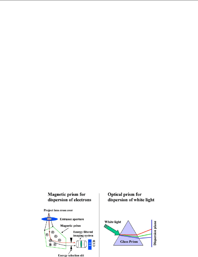
Analyzing the energy lost by some of the electrons after the interaction with the specimen is
known as EELS, as schematically illustrated in Figure 16.53. EELS is not only a tool for
chemical composition analysis, but can yield chemical bonding information. In principle, one
of the inelastic scattering processes is the excitation of the core electron to the unoccupied
energy level, which is a process governed by the quantum dipole selection rule, l = ±1, with
l being the angular momentum quantum number. Similarly to the X-ray absorption process,
which can be divided into X-ray absorption near-edge structure (XANES) and extended X-ray
absorption fine structure (EXAFS), EELS can also be divided into two sections: energy loss
near-edge structure (ELNES) and extended electron energy loss fine structure (EXELFS).
Therefore, the information obtainable with XANES can be similarly obtained using ELNES,
and at the same time, ELNES has the advantage of high spatial resolution such as analysis of
chemical composition from one atomic column to the next. The ELNES feature in essence
maps out the unoccupied density of states with a specific angular momentum quantum number.
For example, if a K-edge EELS spectrum is recorded, that will give the density of states
Figure 16.53: Schematic drawing showing the operating principle for the acquisition of electron
energy-loss spectra with the spectrometer post-column attached to a TEM (left panel), which is
analogized by the dispersion of a ray of white light by an optical prism (right panel).
