Martin P.M. Handbook of Deposition Technologies for Films and Coatings, Third Edition: Science, Applications and Technology
Подождите немного. Документ загружается.

Characterization of Thin Films and Coatings 791
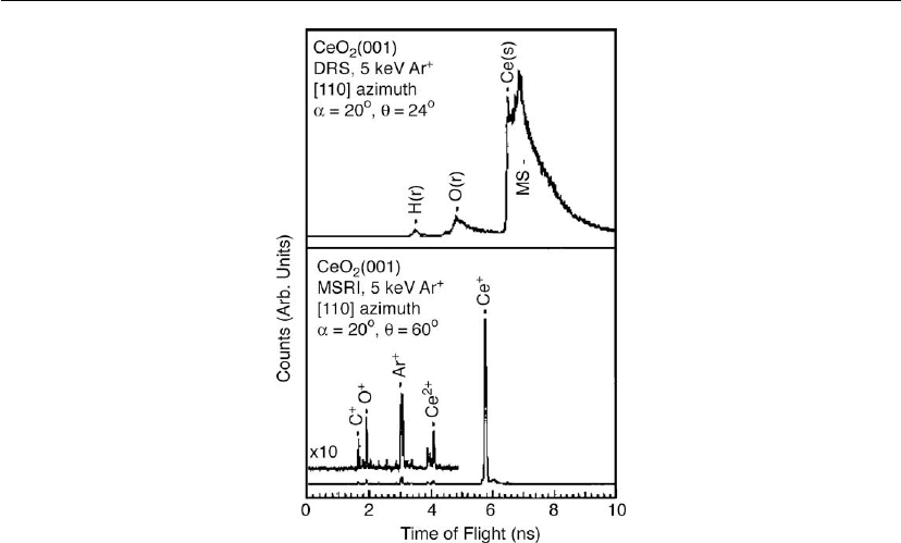
Figure 16.24: Direct recoil spectroscopy (upper panel) and mass spectroscopy of recoiled ions
(lower panel) results from the CeO
2
(001) surface after annealing to 925 K in an oxygen
background of 1 ×10
−7
torr, and cooling to 295 K before evacuating the oxygen [90].
these methods provided much more information about surface structure [87–89]. In MSRI
capability, TOF methods and time-focusing electrostatic analyzers are used to separate the
isotropically resolved mass spectrum. The high-mass resolution and the inherent surface
sensitivity available with the MSRI technique provide a powerful capability for structure
measurements.
As an example, Herman [90] used angle-resolved MSRI (AR-MSRI) to examine the surface
structure of the CeO
2
(100) surface. These measurements were made in a custom-built
ultrahigh vacuum (UHV) chamber at the Environmental Molecular Sciences Laboratory
(EMSL). A 5 keV pulsed Ar
+
ion beam was used at an incident angle of 20
◦
with the sample
surface. The AR-MSRI measurements were made in an electrostatic analyzer which was
positioned at a 30
◦
scattering angle (60
◦
between the incident ions and the recoiling ions).
Typical DRS and MSRI data from this surface are presented in Figure 16.24.
In DRS, the main signals obtained were hydrogen and oxygen recoils, argon single scattering
from cerium, and multiple scattering events. In the MSRI spectrum the signal from Ce
+
dominates and the area under this peak can be collected as a function of azimuthal angle to
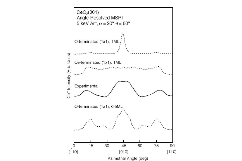
obtain the structural information. Figure 16.25 shows the experimental AR-MSRI data for Ce
along with the calculated values for three different models such as oxygen-terminated full
one-layer (1 ×1) surface, cerium-terminated full one-layer (1 ×1) surface, and
oxygen-terminated half-monolayer surface.
792 Chapter 16
Figure 16.25: Angle-resolved mass spectroscopy of recoiled ions intensities for cerium with
respect to azimuthal angle. The experimental data are shown as a solid line and calculated data
are shown as dashed lines for the models discussed in the text [90].
As clearly seen in the figure, the best fit for the experimental data is obtained for an oxygen
terminated surface that has 0.5 ML of oxygen removed. As discussed in this example, the
MSRI technique has much higher mass resolution than either LEIS or DRS, and AR-MSRI
can effectively determine the surface structure by comparing the experimental data with
simulations.
Strengths:
Determination of surface structure and terminations of single crystal surfaces.
Surface composition with high sensitivity.
Non-destructive analysis.
Limitations:
Limited analysis depth (few monolayers).
Neutralization issues with inert gas ions.

Characterization of Thin Films and Coatings 793
16.4.1.2 Medium-Energy Ion Scattering
Since MEIS typically utilizes 100 keV ions as incident particles and electrostatic analyzers to
detect the scattered ions, it is a refinement of the more common technique of RBS, but with
enhanced depth and angle resolution. In general, collimated light ions such as H
+
and He
+
are
used in MEIS experiments. The incident ions are generally aligned with a particular known
direction and the energy and angle of the scattered ions are analyzed simultaneously to
measure atomic mass, depth, and surface structure. As explained in the subsections at the
beginning of this ion scattering section, mass and depth are determined. MEIS can achieve a
depth resolution of one atomic layer in many cases. To calculate the surface structure the
scattered intensity measurements are performed as a function of azimuthal and polar angles
when the incident ion beam is aligned with a crystallographic axis. When the ion beam is
aligned with a crystallographic axis the surface atoms shadow deeper atoms from the ion
beam. For a particular crystal, this alignment along certain incident directions can allow the
ion beam to illuminate only the top one, two, or three layers, according to choice. Ions
scattered from the second layer will have their outward paths blocked at certain angles by first
layer atoms. The angular variation of scattered ions can be related to the geometrical
arrangement of surface atoms. The experimental data should be compared with computer
simulations to determine the complete surface structure.
Goncharova et al. [91] analyzed high-quality single crystal SrTiO
3
(STO) films grown by
molecular beam epitaxy on Si substrates using MEIS. The investigators used a 98–130 keV H
+
beam aligned along one of the low index directions of the Si substrate and an electrostatic
analyzer to collect the backscattered ions. In this type of experimental set-up, it is possible to
obtain subnanometer depth resolution, which is significantly higher in MEIS experiments than
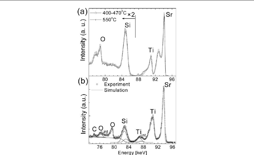
in normal RBS using high-energy ion scattering. Figure 16.26 shows the energy distribution of
the backscattered protons collected in this experiment.
The data shown in Figure 16.26(a, b) were collected from 3.5 nm and 7.8 nm thick STO films,
respectively. The signals from Sr, Ti, and O sublattices in the films and Si from the substrate
are well separated and the features grown at the STO/Si interface due to annealing are clearly
visible.
Depth profiles of elements were obtained by performing computer simulations of the
backscattered ion energy distributions [92, 93]. However, the depth resolution differs for
different species and varies for deeper layers. Near the surface region, quantitative depth
profiles for different species can be extracted with a resolution as high as 0.3 nm. Because of
energy straggling, the depth resolution deteriorates in deeper layers. In general, the calculated
resolution depends on the film material. For ZrO
2
thin films, the depth resolution at a depth of
3 nm is approximately 0.8 nm.
794 Chapter 16
Figure 16.26: MEIS energy distributions for (a) 3.5 nm thick STO films on Si(001) recrystallized
at 450 and 550
C, and (b) a 7.8 nm thick STO film recrystallized at 550
C. Interface peak
deconvolution is demonstrated for 7.8 nm film [91].
Strengths:
Absolute quantifications of film thickness and stoichiometry of heavy element films on
light element substrates.
Very high depth resolution.
Crystalline quality measurements and lattice site locations of dopant in single crystals.
Determination of surface structures.
Limitations:
Limited analysis depth (∼100 nm).
Difficult for light element films on heavy element substrates.
16.4.1.3 High-Energy Ion Scattering Methods
RBS and channeling
Incident ions with energies ranging from 0.5 to 4 MeV are used in HEIS investigations.
High-energy ion scattering (especially RBS and channeling techniques) have been extensively
Characterization of Thin Films and Coatings 795
used to study the stoichiometry, structure, and thickness of thin films. In these experiments, a
He
+
ion beam is incident on the sample (film on a substrate) with an energy that is typically
between 0.5 and 2.0 MeV. In this regime, the Coulomb scattering can be treated classically
(Rutherford scattering) and as a result, reasonably accurate numerical simulations of the ion
scattering yield can be performed. As explained earlier, this technique is element specific since
the recoil energy of the backscattered He
+
ion is mass dependent. Since the ion loses energy as
it travels through the target material, an energy spectrum of the backscattered ions also yields
information about the depth of the backscattering event. On the other hand, if the ion beam is
well aligned with a major axial direction of a single crystal target, the ions channel into the
crystal along the relatively open areas between the rows of atoms. Ions which backscatter from
the first (surface) atom in each row give rise to the surface peak observed in the backscattered
ion energy distribution curve, while the small-angle forward scattered ions form a shadow cone
which extends into the solid. Subsequent atoms along the row and within the shadow cone do
not lead to backscattering events, for a static model of an ideally terminated bulk lattice. By
rotating the sample by a few degrees with respect to the angle of incidence away from the low
index direction, the channeling mode becomes a random mode. In this mode, virtually all the
atoms in the sample are exposed to the ion beam and as a result the highest backscattered ion
yield can be obtained. The variation of integrated yield over a small region near the surface
peak as a function of tilt or polar angle produces an angular yield curve or rocking curve.
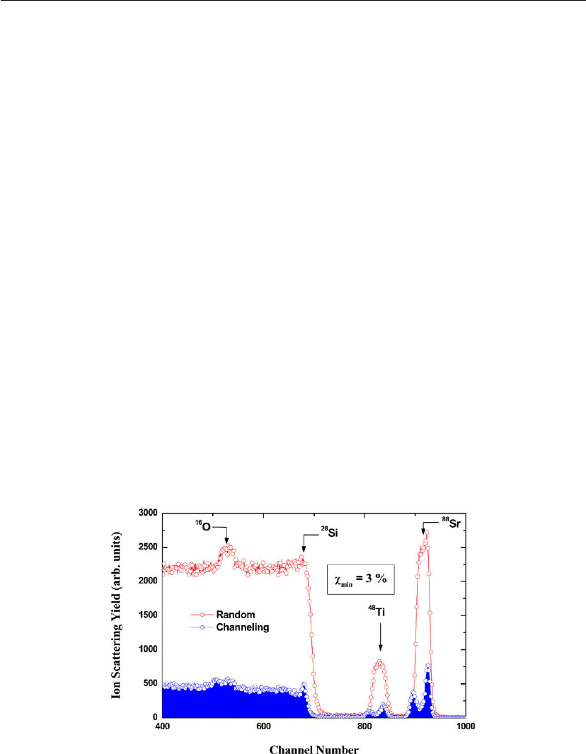
As an example, RBS and channeling measurements performed along the <100> direction of
40 nm thick SrTiO
3
films that were grown on Si substrate is shown in Figure 16.27 [94]. Since
Sr and Ti in the films are much heavier than the Si in the substrate, the backscattered He
signals from Sr and Ti appear without any interference from the backscattered He signals from
Figure 16.27: RBS spectra measured along channeling (blue) and random (red) direction of 400
´
˚
A
thick SrTiO
3
on Si [94].
796 Chapter 16
Figure 16.28: Channeling spectrum from 400
´
˚
A thick SrTiO
3
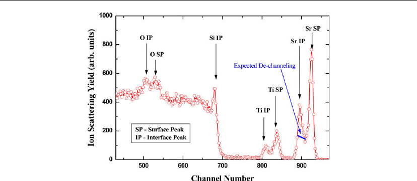
film on Si substrate. Individual peaks
not apparent in the random direction appear, providing additional information about the film
structure. Sr surface peak (SP), Sr interface peak (IP), Ti SP, Ti IP, Si IP, O SP and O IP are
identified in the spectrum.
Si in the RBS spectrum. The stoichiometry of the film was determined to be Sr:Ti:O = 1:1:3
using SIMNRA simulations. The film thickness (39.6 nm) was also measured using the width
of the Sr and Ti peaks assuming the bulk density of the SrTiO
3
. The minimum yields (the
ratios of the aligned yield to the random yield just below the surface peaks) for both Sr and Ti
are approximately 3%; thus, the film appears to be well ordered and compares to high-quality
bulk SrTiO
3
single crystals.
When the channeling spectra were carefully examined, seven distinct peaks were visible, as
presented in Figure 16.28. The first peak on the high-energy side is the surface peak from Sr
atoms at the top of the film (Sr-SP). The second peak is attributed to some Sr atoms visible to
the ion beam at the SrTiO
3
/Si interface (Sr-IP). Similarly, the next two peaks are surface
(Ti-SP) and interface (Ti-IP) peaks related to Ti atoms. Some Si atoms at the interface are also
visible to the ion beam and this is evident from the fifth peak in the spectrum (Si-IP). The sixth
peak is related to the backscattered ion contribution due to the surface oxygen atoms (O-SP)
from the film, and the last peak is due to the visibility of oxygen atoms to the ion beam at the
interface (O-IP). Sr, Ti, and O interface peaks are composed of the normal dechanneling yield
in these three sublattices plus the dechanneling from disordered atoms, which are not aligned
with the ion beam in the interface region. Normal dechanneling yield in the film is expected to
be significantly lower compared to the interface peak areas and, as such, these peaks are
generated mostly due to backscattering yield from disordered atoms in the interface region.
IP/SP ratios calculated using the atomic areal densities are approximately 0.65 for Sr and Ti,
and 1.04 for O. The difference in IP/SP ratios between Sr, Ti, and O indicates that the degree

Characterization of Thin Films and Coatings 797
of disordering associated with interfacial Sr and Ti is approximately the same, but significantly
less than that of O. Additional interfacial oxygen disordering can be attributed to the oxygen
atoms in the reported amorphous silica and silicate-like layers. However, the contribution from
the silicate-like template layer cannot be separated from the amorphous silica layer by RBS
owing to the lack of depth resolution (∼20 nm). Nevertheless, such a silicate-like layer can be
identified and separated from the amorphous silica in XPS spectra. The visibility of Si atoms
in the interface region can be due to the Si atoms in the amorphous silica and silicate-like
layers, and those not completely shadowed by the SrTiO
3
film.
Strengths:
Absolute quantifications of film thickness and stoichiometry of heavy element films on
light element substrates without the use of standards.
Buried interface analysis up to 1000 nm.
Crystalline quality measurements and lattice site locations of dopant in single crystals.
Limitations:
Poor depth resolution.
Difficult for light element films on heavy element substrates.
Nuclear reaction analysis
As mentioned earlier, RBS is ideal technique for depositing thin film of high Z materials on
low Z substrates. For the other cases, such as low Z thin films on high Z matrix, quantification
of light elements is difficult using RBS. However, other ion beam based techniques such as
NRA and TOF heavy ion ERDA are available for light element detection. In NRA, an
incoming energetic particle (usually a proton or deuteron) interacts quantum mechanically
with light element atoms and produces some other particles (e.g. neutrons, protons, and alpha
particles) and gamma rays. Most of the light elements and their isotopes can be detected and
quantified using NRA. Some of the commonly used nuclear reactions are H(
19
F, γ)
16
O,
D(d, p)T,
16
O(d, p)
17
O,
18
O(p, ␣)
15
N,
12
C(d, p)
13
C, and
14
N(d, p)
15
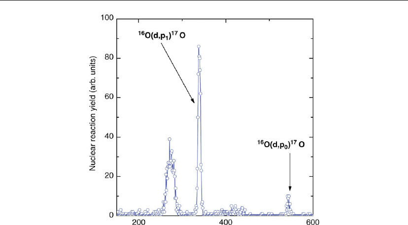
N. As an example, a NRA
spectrum obtained from the SrTiO
3
deposited on Si is shown in Figure 16.29. Since the nuclear
reaction cross-sections can be measured experimentally, we can quantitatively measure the
total amount of oxygen in the film by measuring the area under the proton peak. By combining
RBS and NRA one can easily study the film stability under various annealing environments.
Strengths:
Absolute quantifications of light elements and their isotopes.
Quantitative hydrogen depth profiling.
798 Chapter 16
Figure 16.29:
16
O(d,p
1
)
17
O nuclear reaction spectrum from 400
´
˚
A thick SrTiO
3
on Si.
Buried interface analysis.
Lattice site locations of anion dopant(s) in epitaxial oxide films.
Limitations:
Poor depth resolution.
Large data collection time.
More cross-section data needed.
Advanced elastic recoil detection analysis
When the incident particles hit the target at an off-normal angle with energy in the range
0.05–5 MeV per nucleon, target nuclei recoil elastically from the target surface. Detecting
recoiling target nuclei to acquire information on the target composition is termed elastic recoil
detection analysis (ERDA). Since the mid-1980s, ERDA has undergone rapid development by
a number of groups.
ERDA is similar to RBS but has a number of important differences. For MeV helium ions,
commonly used in RBS because of the elastic nature of the scattering process, the primary ions
backscattered from the heaviest elements have the highest energy. Since these high-energy
particles can be detected without background and the scattering cross-section increases with
Characterization of Thin Films and Coatings 799
increasing target Z, this method of backscattering results in good sensitivity for the heavier
elements in the sample surface region. The ratio of the cross-sections can be approximated by
dσ
light
/dσ
heavy
≈ (Z
light
/Z
heavy
)
2
for M
1
M
2
. This implies that it is very difficult to measure
low-Z elements when the matrix consists of heavy elements since the signal will be very
difficult to observe in the presence of the large signal from the heavy elements.
In a single collision, momentum considerations prevent scattering of projectile ions in
backward directions when M
1
> M
2
. Therefore RBS is completely insensitive to target
elements that are lighter than the projectile ions. However, by using a detector in a forward
scattering geometry, one can detect forward-scattered heavy projectiles and recoiling atoms
from a single collision. The detection of elastically scattered recoils is the basis of ERDA. For
the case of ERDA with heavy ions (M
1
M
2
), the cross-section for recoils is approximately
proportional to Z
2
/M
2
and therefore almost constant. This implies that the recoil cross-section
does not decrease dramatically for light elements, which is the case for RBS, as discussed
above. Furthermore, the use of a heavy-ion beam in ERDA makes it possible to reduce the
scattering of the primary beam into the detector by placing the detector at an angle φ > θ
max
,
thereby enhancing the sensitivity. θ
max
= sin
−1
(M
2
/M
1
) and is typically 20–40
◦
for heavy
projectiles such as
81
Br. The ability of ERDA to detect light and heavy elements makes it
unique in its ability to quantitatively characterize surface film structures on a nanometer
scale.
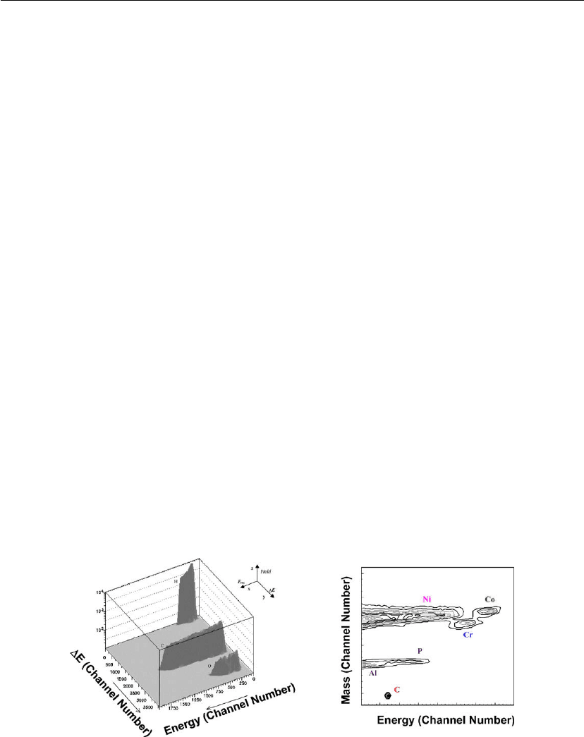
As one of the most promising ion beam analysis techniques, ERDA combined with a
multidispersive detector telescope, such as a time-of-flight (TOF-E) detector telescope
or thin Si detector (E-E), provides simultaneous detection and absolute quantification of
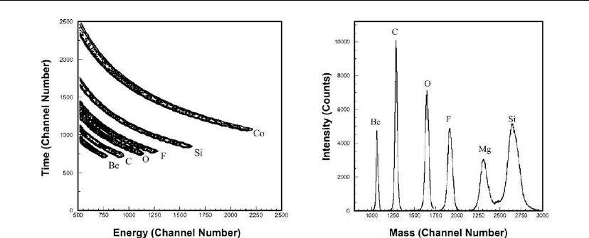
elemental depth profiles in complex matrices. Two powerful ERDA techniques are shown in
Figure 16.30 and TOF-E ERDA is shown in Figure 16.31.
Figure 16.30: Two experiments of ERDA spectra. Left: 3D representation of a E-E ERDA
histogram of a sample containing H, C and O. Right: complex C/Co/Cr/Ni-P/Al multilayer
structure with elements of close atomic mass obtained from TOF-E ERDA.
800 Chapter 16
Figure 16.31: Two examples of TOF-E ERDA spectra. Left: simultaneous detection of elements:
Be, C, O, F, Si, and Co using TOF-E ERDA. Right: good mass separation using TOF-E ERDA.
ERDA provides characterization of multielemental stoichiometry in multilayer thin films or
complex matrices (Figures 16.30 and 16.31) from the surface to depths of about 1 m with
nanometer depth resolution. Since this is a powerful method to investigate elemental
concentrations in the surface regions, this capability can be effectively applied in many
different areas including characterization of oxide thin films for optical, magnetic and
catalytic applications and characterization of environmental and biological samples. Both
E-E and TOF-E ERDA techniques can be applied to study hydrogen absorption,
desorption, and diffusion, which are important in hydrogen storage, separations, and
catalysis.
Strengths:
Quantitative depth profiles of light elements including their isotopes.
Good depth resolution.
Good mass resolution for lighter atoms.
Limitations:
Destructive analysis.
Limited analysis depth (up to 1000 nm).
Poor mass resolution for heavier atoms.
