Martin P.M. Handbook of Deposition Technologies for Films and Coatings, Third Edition: Science, Applications and Technology
Подождите немного. Документ загружается.

Sputter Deposition Processes 281
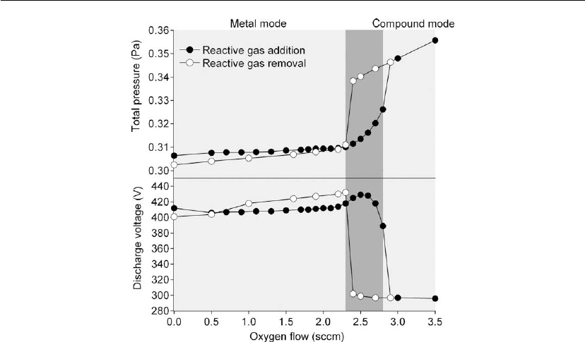
Figure 5.16: Discharge voltage and total pressure behavior during reactive magnetron sputtering
of Al in an Ar/O
2
mixture. The argon pressure and the total current were kept constant at 0.3 Pa
and 0.3 A.
briefly reviewed in this chapter. A user-friendly, shareware code, entitled RSD2009 [43],is
available.
The model is based on balance equations, an approach followed by many authors, and
originally proposed by Berg et al. The first balance equation is related to the flow:
q
0
= q
P
+ q
R
+ q
S
(5.21)
and states that the reactive gas flow introduced into the vacuum system (q
o
) must equal the
sum of the reactive gas flows to the pump (q
p
), and the number of reactive gas molecules
consumed per unit time in reactions at the target (q
T
), and at the substrate (q
S
). The reactive
gas flow toward the pump depends solely on the partial pressure of the reactive gas P and the
pumping speed S, and can be expressed as
q
P
= PS (5.22)
The reaction on the substrate between the reactive gas molecules and the deposited target
material is described as by Berg et al. as a chemisorption process. Hence, the flow toward the
substrate will depend on the reactive gas coverage at the substrate, θ
s
. It will also depend on
the sticking coefficient of the reactive gas α
s
and the substrate area A
s
. The latter expresses the

282 Chapter 5
area of all surfaces on which deposition occurs. Hence, the term ‘substrate’ refers to the entire
system except the target. Summarizing,
q
S
= α
s
F
(
1 −θ
s
)
A
s
(5.23)
with F the flux of reactive gas molecules toward the substrate. This latter term is defined as
F =
P
√
2πmkT
(5.24)
with m the mass of the reactive gas molecule, k the Boltzmann constant, and T the gas
temperature.
The reaction at the target cannot be described solely by reactive gas chemisorption. One must
include other reaction paths. In the model proposed by Depla et al., two mechanisms are
included, i.e. direct reactive ion implantation and knock-on of chemisorbed atoms into the
target. Including these extra reaction paths makes the model more complex but strongly
enhances the understanding of reactive magnetron sputtering. In the model, one distinguishes
between the surface layer and the subsurface region. Using this description of the target, the
steady-state flow toward the target can be written as
q
t
=
Fαθ
sm
−
Iβθ
sc
2
+
z
2
Y
s
θ
rb
A
t
(5.25)
with A
t
the target surface area and z defined by the stoichiometry of the compound MR
z
with
M the metal and R the reactive gas. Equation (5.25) takes into account chemisorption of the
reactive gas on the metal fraction of the target, θ
sm
. Knock-on of chemisorbed atoms into the
target will depend on the ion current density I, the knock-on yield β, and the fraction of the
target covered with chemisorbed oxygen atoms θ
sc
. Finally, direct reactive ion implantation is
also included. In this mechanism, the compound is formed in the subsurface region of the
target and, owing to target erosion, it reaches the surface. The fraction of the compound in the
subsurface region, i.e. just beneath the surface layer, is expressed as θ
rb
. The target erosion is
defined by the ion current density and the total sputter yield of the target Y
s
, which depends on
the surface composition:
Y
s
= θ
sm
Y
m
+ θ
sc
Y
c
+ θ
sr
Y
r
(5.26)
with θ
sr
the compound surface fraction and Y
r
, the compound yield. Clearly,
θ
sm
+ θ
sc
+ θ
sr
= 1 (5.27)
The next step in the model is to calculate the different surface and bulk fractions of compound
and unreacted target material. We need also to calculate the reactive gas substrate coverage, θ
s
.

Sputter Deposition Processes 283
This latter term is perhaps the easiest to start with. Essentially three processes occur at the
substrate:
chemisorption of reactive gas on the metal fraction of the substrate
sputter deposition of compound onto the substrate
sputter deposition of metal onto the substrate.
These three processes lead to the following steady-state equation:
2F
z
α
c
(
1 −θ
s
)
+
(
Y
c
θ
sc
+ Y
r
θ
sr
)
IA
t
A
c
(
1 −θ
s
)
−
Y
sm
θ
sm
IA
t
A
c
θ
s
= 0 (5.28)
For simplicity, compound sputtering is described as molecular, but in reality the compound
will leave the target primarily as atoms.
Implicitly, this equation assumes a uniform deposition profile, which is of course too simple.
By subdividing the substrate in different areal cells, with areas A
c,i
and calculating the metal
and compound flux arriving at each substrate cell using a transport code (see next section), one
can describe the condition of the substrate locally by solving Eq. (5.22) for θ
s,i
, the condition
of each substrate cell. This gives a much better description of the substrate composition as a
function of the oxygen flow.
Similarly, we describe the surface and bulk condition of the target. At the surface, three
processes are described by the model: chemisorption, knock-on, and sputtering, which leads to
the following relations:
2F
z
αθ
ms
= Y
c
θ
cs
I +
I
z
βθ
cs
I
z
βθ
cs
+ IY
c
θ
mb
= Y
m
θ
ms
I +
2F
z
αθ
ms
v
s
(t)θ
rb
n
o
= Iθ
rs
Y
r
(5.29)
The first equation describes the balance between chemisorption (left side) and sputtering of the
chemisorbed atoms and knock-on events (right side). The second equation describes the metal
surface balance. Knock-on processes of chemisorbed atoms result in an increase in the metal
surface fraction. We must also take into account that metal from the bulk is transported toward
the surface owing to target erosion. At the right side, two mechanisms leading to a decrease of
the metal fraction are described, i.e. sputter removal and chemisorption. The third equation
describes the balance between sputter removal of compound material and the transport of
compound from the subsurface region to the surface region, defined by the target erosion
speed v
s
.

284 Chapter 5
To include the reaction of the implanted and knock-on implanted reactive gas atoms with the
target material, one needs to account for target erosion, implantation, and chemical reaction.
This leads to the following equations:
∂n
r
(x, t)
∂t
= 2 fIp(x) − kzn
r
(x, t)n
m
(x, t) + Iθ
cs
βp
c
(x) − v
s
(t)
∂n
r
(x, t)
∂x
∂n
m
(x, t)
∂t
=−kn
r
(x, t)n
m
(x, t) − v
s
(t)
∂n
m
(x, t)
∂x
(5.30)
The first describes the time evolution of the concentration n
r
of non-reacted implanted reactive
gas atoms, while the second does the same for the concentration n
m
of non-reacted target
atoms. The amount of reactive gas atoms which becomes implanted depends on the mole
fraction f of reactive gas molecules in the discharge. The directly implanted reactive atoms are
distributed over the subsurface region according to the implantation profile p(x). A similar
approach can be used to describe the distribution of knock-on implanted atoms, i.e. p
c
(x). As a
result of target erosion, there is material transport toward the target surface (last term in both
equations). The chemical reaction between both the reactive gas atoms and the target atoms is
defined by their concentrations and the reaction rate constant k. In steady state, these equations
simplify to
v
s
∂n
r
(x, t)
∂x
= 2 fIp(x) − kzn
r
(x)n
m
(x) + Iθ
cs
βp
c
(x)
v
s
∂n
m
(x, t)
∂x
=−kn
r
(x)n
m
(x)
(5.31)
The cascade of equations in the model can be solved quite easily by iteration. One assumes a
given target subsurface reaction, i.e. θ
rb
. For a given partial pressure of reactive gas, one can
calculate, using Eqs (5.29), the target surface condition and the erosion rate. This enables the
solution of Eqs (5.31), which describe the target subsurface condition. At steady state, the
calculated reaction state should equal the initial value. If the value obtained is too high,
the partial pressure (or the mole fraction), is altered, and the calculation is repeated. With the
calculated surface and subsurface conditions, it is possible then to calculate the flow toward
target, substrate, and pump. By summing these three flows, the target condition, the substrate
condition, and the partial pressure as a function of the reactive gas flow can be calculated. Or
stated differently, a hysteresis experiment can be simulated. To facilitate the use of this model,
a downloadable program was written, which predicts the influence of different parameters on
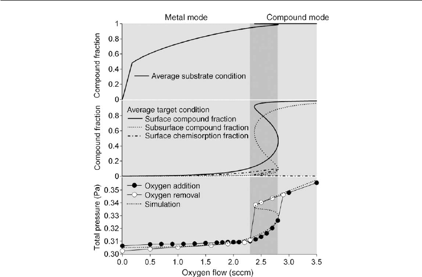
the hysteresis curves [43]. Essentially the program provides an output as shown in Figure 5.17.
Comparing simulation with experimental results (see Figure 5.16) enables the understanding
of the origin of the hysteresis effect. At low reactive gas flow, the partial pressure of the
reactive gas, oxygen in this example, is negligible because most of it is consumed by the metal
deposited on the substrate. Indeed, as Figure 5.17 shows, the target composition remains
Sputter Deposition Processes 285
Figure 5.17: Simulation of the reactive sputter deposition process using RSD2009 [43]. The
experimental results are shown in Figure 5.16.
almost unaffected (middle panel), especially in the subsurface region. Preferential sputtering
enriches the surface region with the compound and, together with the chemisorption of
oxygen, results in substantial surface oxidation. The difference between unaffected subsurface
and oxidized surface regions can explain the small initial increase in discharge voltage noticed
in the experiment during oxygen addition in the metal mode (see Figure 5.16). The oxidation
of the surface region results in a decrease in the total sputter yield, as the compound material
sputters less efficiently than the metal owing to a higher surface binding energy. Hence, less
metal is deposited, and more reactive gas becomes available for target oxidation. An avalanche
situation develops which results in complete and rapid oxidation of the substrate and the target.
This also causes an abrupt change in the partial pressure and other deposition parameters such
as discharge voltage. The simulation shows that within the hysteresis region (dark shaded
area), the slope of the partial pressure vs flow curve is negative. Hence, this region is not stable
under flow control. To return to metal mode from the compound mode, one needs to lower
the oxygen flow to a value smaller than the critical flow measured during the flow increase.
This behavior is due to the large difference in sputter yield between the metal and the
compound.
286 Chapter 5
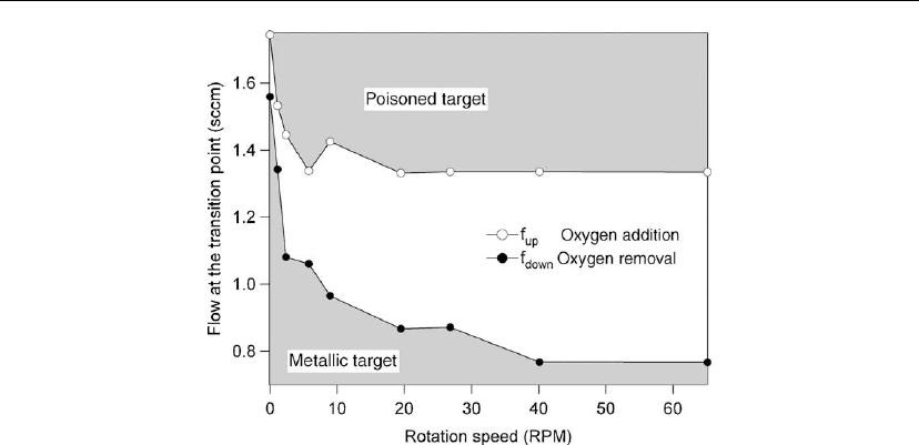
Figure 5.18: Flow at the transition points as a function of the rotation speed.
For rotating cylindrical magnetron, the hysteresis is also a function of the rotation speed.
Figure 5.18 shows the behavior of the critical point as function of the rotation speed for the
laboratory scale rotating magnetron depicted in Figure 5.11.
Understanding this behavior requires a time-dependent, rather than a steady-state, description
of the reactive sputter process, because, owing to target rotation, processes which occur
outside the racetrack influence the process as that region rotates into the discharge. Moreover,
an additional process must be taken into account, i.e. redeposition of sputtered material onto
the cathode [44].
5.5.3 Circumventing the Hysteresis Problem
Hysteresis behavior hinders the application of reactive magnetron sputter deposition. Indeed,
when controlling the process by regulating the flow, one notices that the smallest change in the
reactive gas flow and/or other deposition conditions can result in a runaway situation from
metal mode to compound mode. Optimal use of reactive magnetron sputter deposition appears
to require using a reactive gas flow close to the edge of the metal mode region, as this
combines nearly stoichiometric compound layers with a high deposition rate. The problem
with this is that minor perturbations in the discharge, which always occur, are amplified and
move the system beyond its metastable operation point. However, several solutions are
available. A first solution, as described by Berg et al. [40], requires a dramatic increase in
pumping speed. In this situation, hysteresis will be avoided, as the reactive gas partial pressure
in the vacuum chamber is to a large extent controlled by the pump, and not by the deposition

Sputter Deposition Processes 287
process. However, this is not a cost-effective solution. An alternative approach was proposed
by Sproul et al. [38]. The reactive gas flow is controlled by a feedback system which measures
the partial pressure of the reactive gas, the optical emission spectrum of the metal, or the
discharge voltage. So, one switches from flow control to partial pressure control. Indeed, as
simulation results show (see Figure 5.17), if one interchanges pressure and flow axes, full
control is possible and one can combine complete compound formation with a relatively high
deposition rate. The disadvantage of this approach is the complexity and the cost of the
equipment. Another solution is using conductive substoichiometric targets (e.g. TiO
2-x
with x
of the order of 0.2 [45]), for which only a low reactive gas flow is required, and generally the
deposition process does not show a hysteresis behavior. However, substoichiometric target
processing is more expensive and complicated as these targets are mostly ceramics. In
conclusion, circumventing the hysteresis problem is possible, but it always comes with an
additional cost and/or increased system complexity.
5.6 Moving Toward the Substrate
5.6.1 Sputtered Particles
All sputtered particles leaving the target can collide with the gas atoms present in the vacuum
chamber during transit to the substrate. The same is true for ions which are neutralized and
reflected at the target, and for negative ions formed at the target [46]. Collisions will alter
particle energy, direction, and momentum, and therefore also the morphology and
microstructure of the growing film (see next section). The most important parameter
influencing gas phase transport is pressure.
Several models have been proposed [47] to simulate the transport of sputtered particles.
Recently, Van Aeken et al. [48] have developed a user-friendly shareware model, SiMTRA
(Simulation of Metal TRAnsport). This flexible model enables calculation of the energy,
direction, and flux of sputtered particles incident on every defined surface in the vacuum
chamber. The output is not only the deposition profile, but also the energy of the arriving
particles on the substrate. The output of the code can be combined with the reactive sputter
deposition model RSD2008, described in the previous chapter, enabling a more detailed
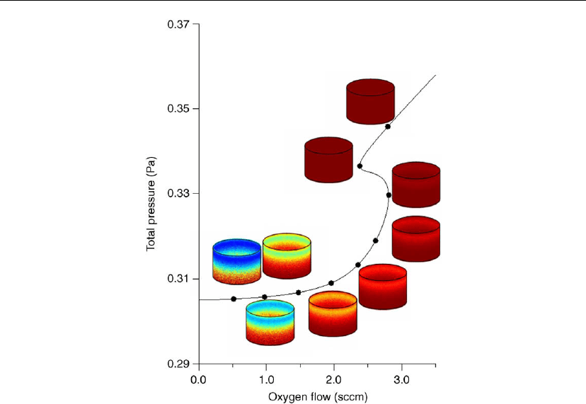
description of the reactive sputtering process. Figure 5.19 shows the result of such a
calculation. Oxidation of the substrate, here a tube with the magnetron source located at the
top center of the tube, is tracked as a function of the oxygen flow. At low oxygen flows, only
the material deposited at the bottom of the tube is fully oxidized (black). As the oxygen flow
increases, all deposited material becomes oxidized. The transition from metal mode to
compound mode occurs when the deposited material is nearly fully oxidized.
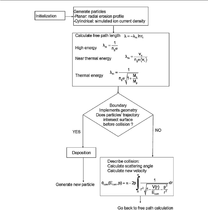
The SiMTRA model provides insight into the mechanisms controlling the transport of
sputtered particles toward the substrate (Figure 5.20). The ejection positions of the sputtered
288 Chapter 5
Figure 5.19: By placing a 5 cm diameter magnetron source in the upper part of a tube, the surface
on which material is deposited is well defined, and the influence of the area of this surface and the
deposition profile on the hysteresis behavior during reactive magnetron sputtering can be studied.
The illustrations shows the result of a simulation in which the deposition profile is included. The
oxidation of the deposited target material is shown on the cylinder. Black represents a fully
oxidized surface, while white represents a pure metal surface. Experimental conditions: constant
argon pressure 0.3 Pa, constant discharge current 0.43 A, pumping speed, 100 l/s. The tube had a
diameter of 26 cm and a height of 53 cm. The oxygen was introduced at the bottom of the tube.
The target material was Al.
particles are based on the (simulated) racetrack of the magnetron. One can use the Thompson
equation (see Eq. 5.5) to describe the energy distribution of the sputtered particles, and the
nascent angular distribution can be calculated using SRIM or can be based on experimental
input. The model assumes that the sputtered particles are neutral atoms in the ground state, and
these atoms only undergo elastic collisions with neutral gas atoms. For DC magnetron
sputtering, this is a reasonable approach for two reasons. First, the ionization degree is
generally very low. Most authors report an ionization degree of the order 0.1% and lower (e.g.
[33, 49, 50]). Second, the sputtered particle density is much less than the gas density. The ratio
between the sputtered particle density and the gas density depends on the pressure and the
Sputter Deposition Processes 289
Figure 5.20: Flowchart for SiMTRA describing all steps during the transport of a sputtered
particle toward the substrate. n
g
: sputter gas density; σ: collision cross-section; v: velocity
(subscripts s: sputtered atom; g: gas atom; r: relative); θ
com
and E
com
: polar scattering angle and
kinetic energy in the center-of-mass system; p: impact par ameter; V(r): interaction potential; R:
distance of closest approach.
power, but is of the order of 10
−4
(e.g. [50, 51]). Based on these assumptions, the path of the
sputtered atom can be described as a sequence of straight trajectories each terminated by a
binary elastic collision with a gas atom, until deposition on a surface occurs. Classical
scattering theory follows [27]. The free path length λ until the next collision is derived from a

290 Chapter 5
mean free path length λ
m
as
λ =−λ
m
lnr
1
(5.32)
with r
1
a random number uniformly chosen over the range ]0,1]. The description of the mean
free path length depends on the velocity of the sputtered particles v
s
compared to the velocity
of the gas atoms v
p
. At high velocity (v
s
>5v
p
), the gas atoms are considered stationary. When
v
s
drops below 5v
p
the thermal motion of the gas atoms is taken into account. Finally, when the
energy of the sputtered particles falls below 3/2 kT the sputtered particle is considered
thermalized.
5.6.2 Other Particles Arriving at the Substrate
Besides the arrival of sputtered particles (see Section 5.6.1), the flux of other particles arriving
at the substrate is important as these particles determine the total energy and momentum flux
toward the substrate and hence they play a crucial role in the thin film growth (see Section
5.7). The total energy flux per incoming metallic particle E
tot
can be described as a linear
summation of different contributions [52–56]:
E
tot
= E
cond
+ E
pl
+ E
t
+ E
sp
+ E
refl
+ E
gas
+ E
el
+ E
ion
(5.33)
as summarized in Table 5.2.
Based on a combination of modeling, and measurements with a Langmuir probe, retarding
field analyzer, quartz microbalance, and energy-resolved mass spectrometer, Mahieu et al.
quantified the total energy flux and showed the relationship with the crystallographic
orientation and microstructure of deposited TiN films [59, 60]. This connects the energy (and
momentum) flux to properties of the films (such as hardness), and to deposition conditions. In
the next section, we focus on the relationship between deposition conditions and
microstructure.
5.7 Sputter-Deposited Thin Films: Morphology and Microstructure
Several authors have attempted to summarize the influence of deposition parameters on film
morphology and microstructure in a single diagram. These diagrams are known as structure
zone models (SZMs). The SZM best known in the sputter deposition community is the one
published by Thornton [61], which shows microstructure and morphology as a function of
deposition pressure and substrate temperature. This historically important model forms the
basis of several studies (e.g. [62]). Recently, Mahieu et al. [63] published an extended structure
zone model (ESZM) which has the advantage that it not only summarizes the influence of
deposition parameters on film microstructure, but also provides insight into sputter-deposited
thin film growth. Hence, film structure (microstructure and crystallographic orientation) is
