Martin P.M. Handbook of Deposition Technologies for Films and Coatings, Third Edition: Science, Applications and Technology
Подождите немного. Документ загружается.

Sputter Deposition Processes 271
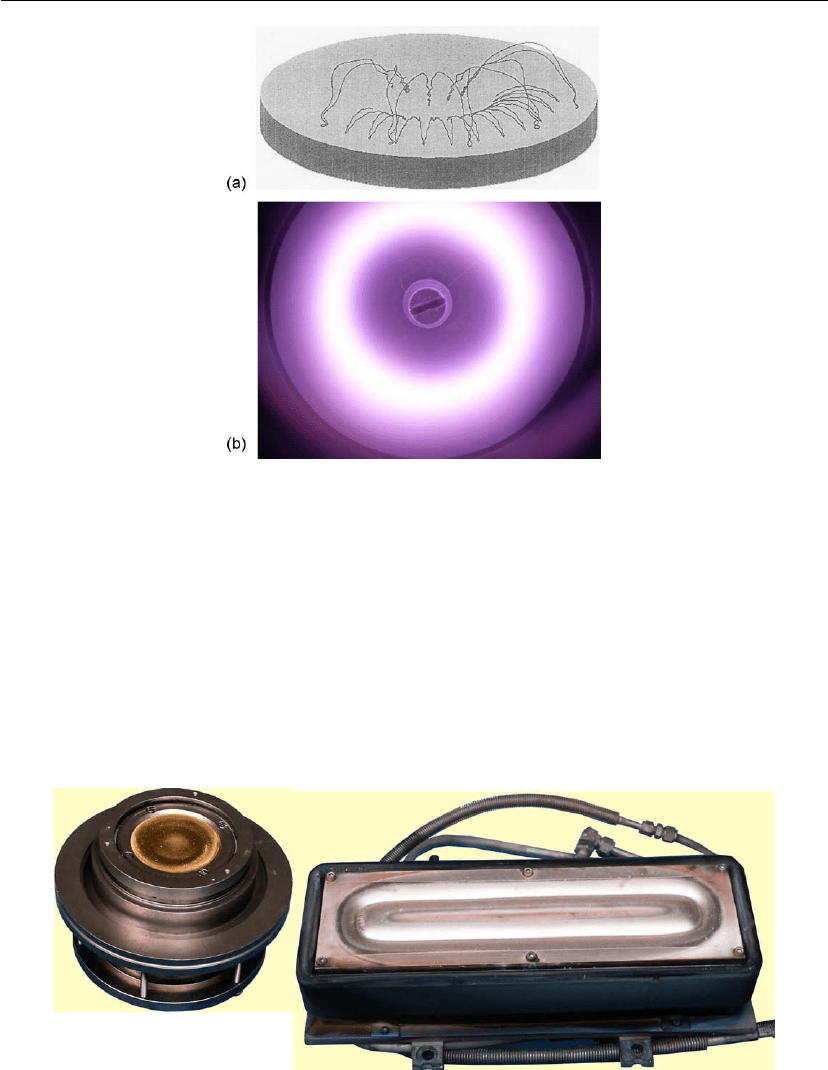
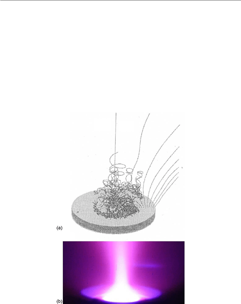
Figure 5.9: Simulated part of a trajectory of an electron on a circular planar magnetron (a) and
the resulting torus-shaped argon plasma (b).
results in a continuously stronger magnetic field strength above the surface because the target
surface recedes toward the magnets as material is sputtered. Hence, the erosion rate increases
(and the voltage usually decreases) as a function of sputtering time. Several companies offer
solutions to increase the target utilization. Optimization of the magnetic field design is a
common solution, but even with an optimized magnet design target utilization remains less
than 50% for stationary magnets. By moving the magnets in a complex geometry under the
target, higher target utilization can be achieved.
Figure 5.10: Two types of planar magnetrons: (left) a circular 5 cm diameter magnetron; (right) a
rectangular magnetron (notice the clear erosion groove or racetrack in both cases).
272 Chapter 5
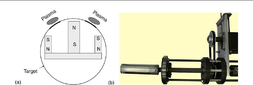
Figure 5.11: Magnet configuration for a rotating cylindrical magnetron (left) and a
laboratory-scale magnetron of this type.
5.4.3 Rotating Cylindrical Magnetrons
To improve target utilization, rotating cylindrical magnetrons have been developed. Their
magnetic field design is quite similar to that of planar magnetrons. However, the target is a
cylindrical tube and is rotated around a stationary magnet configuration (Figure 5.11). The
disadvantage of these magnetrons is the same as for post magnetrons, i.e. a complex target
design and fabrication. For some metals, a tube can be used, but for many materials the target
material must be flame or plasma sprayed onto a cylinder or backing tube, which is water
cooled and holds the magnet configuration. The bearing design is crucial with this magnetron
type as the water flow is inside the vacuum system. The much higher target utilization, up to
85%, is the main advantage. A major problem with planar targets is the build-up of compound
material on the target during reactive magnetron sputtering. The compound layer on
non-sputtered target parts forms the origin of arcing in insulating reactive systems such as
Al/O
2
. With a rotating cylindrical magnetron, this compound layer is sputtered again after
each target rotation, resulting in better process stability during reactive magnetron sputter
deposition.
5.4.4 Some General Features of Magnetrons and Magnetron Discharges
5.4.4.1 The Discharge Voltage
The discharge voltage is an easily measurable quantity and Eq. (5.18) helps to explain its
behavior as a function of experimental parameters. We discuss the most important of these,
and refer to [31] for more details.
When using a planar magnetron, the discharge voltage will decrease as a function of time. This
behavior can be readily explained by the increase in magnetic field strength adjacent to the
target (see Section 5.4.2) due to the erosion groove formation. As such, electrons will move
Sputter Deposition Processes 273
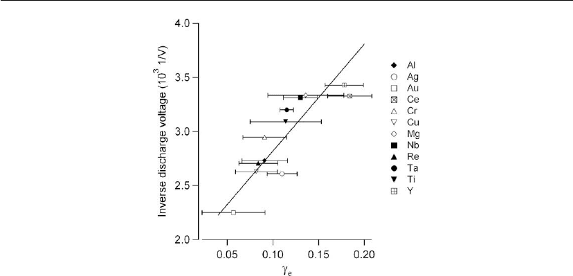
Figure 5.12: The inverse of the discharge voltage measured in pure argon discharges as a function
of the ion-induced secondary electron yield. Measurements are performed with a conventional
5 cm diameter circular magnetron (argon pressure 0.3 Pa, discharge current 0.3 A).
closer to the target, and more sheath ionization will occur, and according to Eq. (5.18) the
discharge voltage should decrease as m becomes larger.
The discharge voltage also depends strongly on the target material and the condition of the
target (see Section 5.5). The material dependence of the discharge voltage can be related to the
value of the ion-induced electron emission yield γ
e
. Changing the target material and/or the
target condition will result in a change in γ
e
, and consequently the discharge voltage will
change. As can be understood from Eq. (5.18), the discharge voltage is, to a first
approximation, inversely proportional to the electron yield, as shown in Figure 5.12.
5.4.4.2 I–V Characteristics
One typical measurement when studying magnetron discharges is the I–V characteristic. The
behavior of the discharge voltage as a function of experimental parameters has been
investigated in detail [32]. Another important parameter is the discharge current, as it is
combined with the discharge voltage to provide power delivered to the target. At constant
pressure, the discharge current increases rapidly with discharge voltage. To express this
relationship, or the I–V characteristics, several empirical scaling laws have been proposed. The
one used most often is
I = kV
n
(5.19)
The exponent n is a measure of the magnetron efficiency, and can have values of the order of
10 or higher. The behavior of the I–V characteristics as a function of the operating pressure is
274 Chapter 5
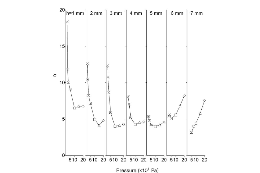
Figure 5.13: The exponent n (see Eq. 5.19)forI–V char acteristics measured under different
conditions of target thickness and pressure. A conventional 5 cm diameter circular magnetron was
used with a copper target. At low magnetic field or for thick targets (see h = 7 mm) the slope
increases with pressure. However, the opposite behavior is observed for a high magnetic field or
thin targets (see h =1orh = 2 mm).
not fully understood. At low magnetic field strengths, the value of n increases with increasing
pressure, but the reverse behavior is apparent at high magnetic field strengths [32], as shown in
Figure 5.13.
The origin of this steep behavior is a current topic of discussion and research as it is related to
the diffusion of electrons perpendicular to magnetic field lines. Based on the description given
above, one could conclude that electrons can only escape from the magnetic trap by losing
nearly all their energy in collisions. This is not completely true; as a result of frequent
collisions with Ar atoms, electrons can be scattered and ‘hop’ between field lines. This
description is the classical diffusion of electrons based on collisions between electrons and gas
atoms. However, experimental work shows that diffusion perpendicular to the magnetic field is
greater than expected from the classical diffusion model [33]. Although several authors have
proposed mechanisms to explain this enhanced diffusion, there are still doubts and unanswered
questions.
Sputter Deposition Processes 275
5.4.4.3 Magnet Balance
The magnet configuration in planar and rotating cylindrical magnetrons is used to trap
electrons, thereby producing a high ion density near the target for a given pressure. With an
optimum design of system geometry and operating pressure, the electrons are lost from the
target area when their energy becomes less than the ionization threshold. Therefore, one can
expect that only low-energy electrons are present in the bulk plasma region and in the vicinity
of the substrate. This can be a distinct advantage to the glow discharge process, but in some
cases (see further) it can also be advantageous to deliver more energy to the substrate. A
possible solution is ‘unbalancing’ the magnetron configuration, or changing the magnetic field
strength of the inner versus outer magnets. In this way, the configuration of the magnetic trap
is changed (Figure 5.14) to allow electrons to escape the magnetic trap follow the magnetic
Figure 5.14: Some simulated electron trajectories for an unbalanced magnetron (a) together with
the cone-shaped argon plasma (b). Note that unbalancing the magnetic circuit opens a ‘leak’ in
the plasma trap and allows independent control of substrate ion bombardment.
276 Chapter 5
field lines toward the substrate. This results in a strong electron flux in the region of the
substrate. By modifying the magnetic field strength balance between the outer and inner
magnets, one can tune the electron flux, and hence the ion flux, incident at the substrate. One
way to characterize the magnet balance is the ratio K between the magnetic flux through the
outer and the inner magnets:
K =
out
in
=
S
out
B
⊥out
dS
out
S
in
B
⊥in
dS
in
(5.20)
where B
⊥
represents the magnetic field strength perpendicular to the magnet, and S is the area
of the magnet [34].
One way of changing the magnet balance is shifting the position of the inner and outer
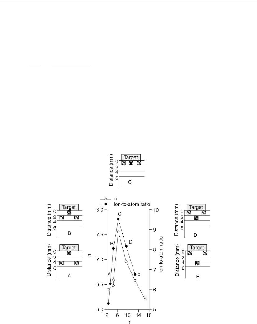
magnets relative to the target surface (Figure 5.15). This results in a different n value for the
I–V characteristic (see Eq. 5.19). Shifting the magnets also changes the discharge voltage,
which modifies the sputter rate of the target at constant current. The combination of both
Figure 5.15: Influence of the magnet balance on the n value (see Eq. 5.19) and the ion-to-atom
ratio. The magnet balance, expressed by the value K (see Eq. 5.20), is changed by shifting the
inner or the outer magnet relative to target surf ace. Several situations are depicted schematically.

Sputter Deposition Processes 277
changes enables one to modify the ion-to-atom ratio at the substrate. The ion-to-atom ratio is a
significant parameter during thin film growth (see Section 5.7).
A more straightforward and completely tunable approach to unbalance the magnetic circuitry
of the magnetron is to incorporate a Helmholtz coil external to the permanent magnets in order
to increase the field strength of the outer magnet [35]. This opens a leak in the plasma trap and
dramatically increases the incident ion/atom ratio at the substrate from typically 0.1–0.5
(depending on the gas, substrate bias, and system geometry) to > 50 with no significant change
in film deposition rates. Moreover, these high ion/atom ratios can be achieved using very low
ion energies (< 10–20 eV) which, in most cases, are below the film damage threshold. Just as
significantly, the ion energy and ion flux incident at the substrate are now controlled
independently by the substrate bias and the external magnetic field, respectively. That is, the
advantages of an ion beam deposition system are now obtainable using high-rate magnetron
sputtering.
5.4.5 Powering the Magnetron
Magnetrons can be powered by a variety of methods. One can choose among radio frequency
(RF), direct current (DC), pulsed DC and, recently, high-power impulse magnetron sputtering
(HIPIMS).
5.4.5.1 Radio-Frequency Magnetron Sputtering
When using thick electrically non-conducting targets, RF power is the only option to sputter
deposit thin films. An important point must be emphasized. The discussion of the magnetron
sustaining mechanisms in Sections 5.4.1 and 5.4.2 is not completely valid for RF powered
magnetrons. Indeed, owing to the rapidly changing electric field, the entire electron distribution
shifts up in energy through ‘in-phase’ collisions, allowing either increased ionization (and,
hence, discharge current) at constant pressure or operation at decreased pressure. The term
‘in-phase’ collisions refers to the fact that there is a fraction of the electron population in the
discharge that, while being accelerated by the instantaneous electric field, will make a collision
before the field direction switches and will then have a velocity component in the direction of
the switched field. Through this mechanism, the overall distribution of electrons increases in
energy and, therefore, the concentration of electrons that have energies above the gas
ionization potential increases, thus decreasing the overall discharge impedance.
When applying a high-frequency (typically 13.56 MHz) power source between two electrodes,
the light (low-mass) electrons respond instantaneously to the rapidly varying field, while the
heavier ions are inertially confined. That is, the ion transit time to either electrode is very much
less than the RF period, forcing both electrodes to charge negatively. In order to maintain
charge neutrality per cycle, the entire RF waveform must then shift down in voltage such that
each electrode is positive (attracting electrons) for less than 1% of an RF period and the ions,

278 Chapter 5
to first order, respond to an average applied voltage which is approximately one-half the RF
peak-to-peak potential. As in DC sputtering discussed above (Section 5.4), the average ion
impact energy is only a small fraction of the applied field owing primarily to charge exchange
collisions. In order to define the target and substrate in RF powered systems, one electrode (the
substrate table) is made to be very much larger than the other electrode (the target) by
electrically connecting the substrate table to the entire system. The electrodes now act as a
leaky capacitively coupled voltage divider for which the applied voltage is distributed as
V
t
/V
s
=(A
s
/A
t
)
m
, where the subscripts t and s refer to target and substrate, A is the electrode
area, and m = 4 in the ideal case, but is typically 1.5–2 for real systems.
An important lesson here is that when using RF power, one is always doing bias sputtering. It
is intrinsic in the nature of how these systems function that there is an average negative voltage
(and, hence ion bombardment) at the substrate. V
s
depends on the pressure, the gas, and
system geometry (i.e. a smaller system confines the plasma and increases V
s
). The substrate
voltage can range from 15–20 V negative to a few hundred volts negative. It is also important
to remember that since RF power supplies are designed to look into circuits with a purely
resistive 50 load, a tunable matching network is required to damp out the complex reactance
(both capacitance and inductance) of the discharge.
The primary disadvantage of the use of RF power supplies, in addition to expense and
reliability, for magnetron sputtering is the inherently low deposition rate. That is, n decreases
significantly in the power-law I–V relationship of Eq. (5.18). This is because magnetron
sputtering, which relies on a closed electromagnetic trap at the target, is fundamentally a DC
concept. The RF field alternately opens and closes the trap, allowing electrons to escape when
the trap is open and forcing electrons to cross magnetic field lines, and hence drop power in the
discharge, which decreases the available power at the target, when it is closed. The deposition
rate for a given applied target power decreases with both increasing frequency [36] and
increasing magnetic field [37].
5.4.5.2 Direct Current Magnetron Sputtering
The simplest and least expensive way to operate the magnetron is using a DC power supply.
Today, special power supplies for sputter deposition have been developed which include an arc
suppression unit. Arcs often occur during reactive sputter deposition of, for example,
non-conductive oxides from a metal target in pure O
2
or mixed Ar/O
2
discharges, due to a
build-up of oxide on the edges of the erosion groove where the sputter rate is low. Arcs (see
Figure 5.5) can be characterized as a low voltage and high current discharge. When the electric
circuit ‘detects’ a strong decrease in the discharge voltage and/or a strong increase in the
discharge current, it switches the power off for a small period (typically a few microseconds)
to draw electrons, decrease charging, and prevent the arc from fully developing. Arcing can
seriously damage a target by local melting, but it also degrades quality of the deposited film
owing to the presence of particulates and/or pinholes while eventually destroying the power
supply.

Sputter Deposition Processes 279
5.4.5.3 Pulsed DC Magnetron Sputtering
An effective way to prevent arcing during reactive magnetron sputtering (discussed below) is
pulsing the applied voltage. In contrast to RF magnetron sputtering, the frequency is much
lower and, is typically 50–250 kHz depending on the application [38]. The discharge voltage
generally cycles between a high negative voltage and a low positive voltage. The negative
voltage part of the cycle is used to perform the sputtering, as the ions bombard the cathode.
The low positive voltage part of the cycle is used to attract electrons to prevent charge
build-up. Because of the higher mobility of the electrons, this part of the cycle can be
relatively short compared to the total cycle time.
An alternative approach is the use of two magnetron sources, i.e. dual magnetron sputtering,
and switching the negative and positive voltage between both targets. In this way, each
magnetron alternately has the function of a sputtering target and an anode. Thus, both targets
can be neutralized during each cycle. This not only prevents charge build-up but also solves
problems related with anodes being covered with insulating thin films (the ‘disappearing
anode’). The disadvantages here are the higher cost and the fact that power to each target
must be turned off before igniting the other target when using mid-frequency AC power
supplies. Thus, transients are more severe in this approach. For pulsed DC dual magnetron
sputtering, plasma ignition may be required after each half-cycle depending on operation
conditions. Dual magnetron power supplies also require electromagnetic and RF interference
shielding.
5.4.5.4 High-Power Impulse Magnetron Sputtering
HIPIMS uses a large energy impulse supplied to the cathode over a very short period, typically
∼100 s. This requires a very different type of power supply, the heart of which is a large
bank of capacitors. The HIPIMS process delivers a large low-energy flux of ions to the
substrate. Peak powers up to several MW/pulse with pulse widths between 100 and 150 s
must be generated by the power supply. Average powers are ∼20 kW with frequencies up to
500 Hz. In addition to supplying pulsed power, arc suppression is necessary. This process takes
advantage of enhanced ionization resulting from the high-energy pulse. Power densities
applied to the target are in the neighborhood of 1–3 kW/cm
2
, compared to traditional
magnetron sputtering with power densities ∼1–10 W/cm
2
.
The high-power pulse is the core of this process. Typical operating conditions are as follows.
The voltage pulse is between 1.3 and 1.5 kV and total pulse duration is ∼120 s. The target
current increases and peaks at ∼200 A as the voltage pulse decays. The power density at that
point is ∼600 W/cm
2
. This method of powering the target results in a high-density plasma
with a high ionization degree of the sputtered target material. During each sputtering pulse, the
discharge begins as gas supported, but owing to the huge powers quickly becomes metal
supported (self-sputtering) due to gas rarefaction. HIPIMS has recently been reviewed in detail
[39].

280 Chapter 5
5.5 Reactive Magnetron Sputter Deposition
Using an electrically conducting, and generally, a metallic target makes powering the
magnetron much easier as several alternatives are now possible. However, it limits the choice
in the materials that can be deposited with this technique. To mitigate this problem, a reactive
gas can be added to the discharge. The reactive gas, e.g. nitrogen, oxygen, or hydrogen sulfide,
can react with the sputtered material to form a compound on the substrate. However, the
addition of the reactive gas to the discharge influences the deposition process in several ways
while increasing the complexity of the overall process. Some aspects of the reactive sputter
deposition processes are discussed in this section.
5.5.1 Hysteresis of Reactive Gas Pressure and Discharge Voltage
To add or remove a reactive gas from the discharge, one generally uses a flow controller. A
typical experiment is to stepwise increase the reactive gas flow over a given interval, and wait
between the steps until the process is stable, at which time the process parameters (pressure,
voltage, current, deposition rate) are recorded. After reaching a maximum flow, the reactive
gas flow is stepwise decreased, and again one gives the system sufficient time to stabilize after
each step. At sufficiently low pumping speed and high discharge current one notices that at a
given reactive gas flow, for many reactive gas/target material combinations, there is an abrupt
change in the total pressure and discharge voltage, as shown in Figure 5.16. One also notices
that the reactive gas flow must be decreased to a much lower value than the critical value
detected during reactive gas addition. Or stated differently, there is a hysteresis in both reactive
gas pressure and discharge voltage. The low oxygen flow region is defined as ‘metal mode’,
and is characterized by a low reactive gas partial pressure and a high deposition rate. The
deposited layer is not a pure compound, but rather a doped metal. The high oxygen flow region
is defined as the ‘compound mode’ or ‘poisoned mode’, with a high partial pressure and a low
deposition rate. The film is essentially a pure compound.
5.5.2 Understanding the Hysteresis Behavior: Modeling the Reactive Sputter Process
To understand the hysteresis behavior, several authors have modeled the process. The most
well known, the ‘Berg’ model, is named after S. Berg from Uppsala University [40]. The
model has value because of its simplicity and the fact that it captures much of the physics of
the process. As stated by Berg et al., the results should be considered as a first order
approximation. Nevertheless, some authors state that the model fits their experimental results.
This statement is dangerous, because the fitted parameters are often not experimentally
verified, or have no physical meaning. Some experimental results can be better explained by
changing the description of the processes occurring at the target, i.e. by including reactive ion
implantation. This was first proposed by Depla et al. [41, 42], and the combined model will be
