Mahle GmbH (Ed.) Cylinder Components: Properties, applications, materials
Подождите немного. Документ загружается.

4.3 Requirements 73
4.3 Requirements
4.3.1 Mass of the connecting rod
As a general principle, moving masses should be kept as small as possible, in order to help
minimize fuel consumption and to reduce vibrational excitation. One such component, the
connecting rod, affects the mass of the components with which it is linked–a lighter con-
necting rod would allow for less piston, balancer, bearing and crankshaft mass. Further
weight can also be saved by reducing the connecting rod length which allows for a lower
deck height. The changes to the lateral forces on the piston skirt, however, must be taken
into consideration.
In order to maintain quiet operation and low vibration levels, the rotating and oscillating
masses should match as closely as possible. The oscillating mass portion is located on the
piston side and the rotating portion is on the crankshaft side. There exist several potential
ways to attain this goal.
The sintering method allows tolerances in raw part weight within a tolerance range of less
than 1%. MAHLE has also comprehensively developed industrial engineering technology for
steel forged connecting rods and significantly reduced the weight variation. The controlled,
fully automated forging process thus allows a tolerance range of less than 1% in the raw
part weight.
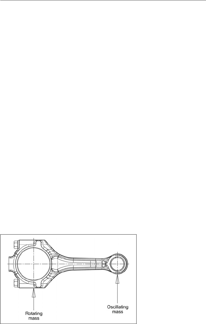
Another option to reduce weight variation is weight grading. The oscillating and rotat-
ing masses of the finished connecting rods are determined and the connecting rods are
divided into different weight classes. For this purpose, the connecting rod is weighed hori-
zontally with two scales, each at the center point of the small end and crank end. The value
at the small end bore corresponds to the oscillating mass, and that of the crank end to the
rotating mass (Figure 4.5).
Figure 4.5:
Distribution of moving masses
of a connecting rod
74 4 Connecting rod
When machining to a target weight, a balance pad is added on the big end boss (if required
on the small end as well), which is machined to adjust to the desired weight.
Only one connecting rod weight grade is installed in a given engine. Because different diam-
eter classes are required for the piston, depending on the finished cylinder diameter, the
assembly unit consisting of piston, piston rings, piston pin, circlips, and connecting rod can
only be assembled together as one predetermined unit right at the engine manufacturing
line for installation.
4.4 Crank end
The diameter of the crank end bore is determined from the crank journal diameter of the
crankshaft and the bearing shell wall thickness. The critical stress acting on the big end is
the inertia force. The oscillating mass loads the crank end bore in tension, and the bore is
ovalized in the axial direction. This results in bending stresses and lateral forces at the parting
surface. It is important that the joint remains closed under all operating points.
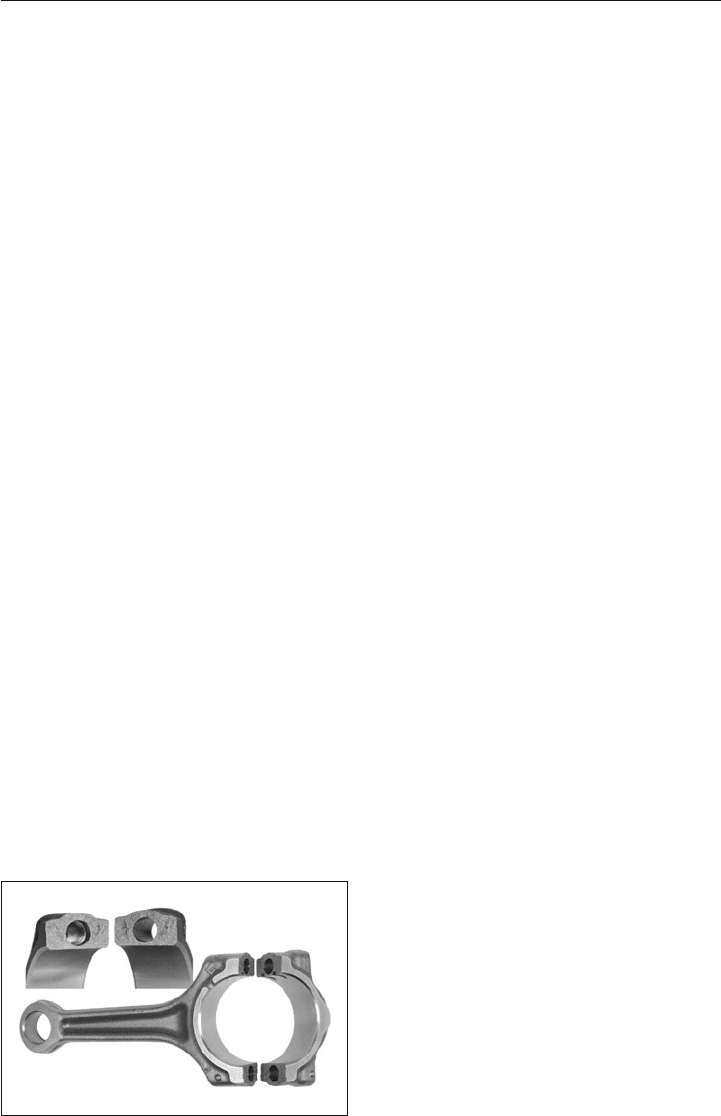
4.4.1 Cracking (fracture splitting)
Cracking, or fracture splitting, of connecting rods has become common practice in recent
years. Nearly all new designs in series production today employ this method to create the
parting in the crank end. The big end is notched inside the bore with a laser or reamer. For
sintered parts, the notch could be pressed in during the manufacture of the blank. Using a
cracking mandrel, the halves are then broken apart (cracked) hydraulically at room tempera-
ture; see Figure 4.6. The resulting parting line (fracture surface) is not machined, and dowel
Figure 4.6:
Fracture surfaces of the crank end, manufactu-
red by cracking
4.4 Crank end 75
sleeves or dowel screws are not needed. The fit is provided solely by the engagement of the
uneven surfaces. The fracture surfaces experience only minimal settling. For optimal fracture
splitting, preventing plastic deformation of the connecting rod material during the process is
critical. Special steel grades with a yield-tensile strength ratio of greater than 75% are used.
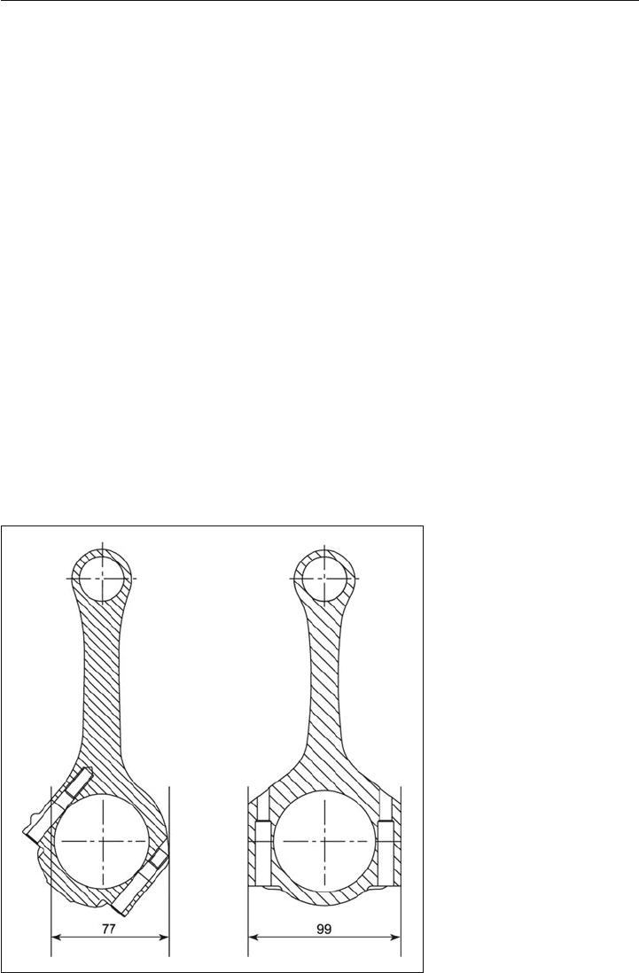
4.4.2 Angle split of the crank end
If the crankshaft has a large crank journal diameter, the crank end must be split at an angle
in order to allow the connecting rod to be installed and removed through the cylinder liner.
This leads to complex loading conditions in the parting joint.
In a connecting rod that is split at an angle (Figure 4.7), the upper blind hole thread is
particularly at risk, because it is located directly in the region of highest stress of the entire
connecting rod. This is the area of alternating tensile and compressive loads, which are
increased further by the notch effect of the thread, resulting in an increased risk of fracture.
The cross section around this thread must therefore be dimensioned carefully.
Figure 4.7:
Angled or straight-split
connecting rod and required
diameter of the cylinder liner
for identical crank journal
diameter

76 4 Connecting rod
4.5 Connecting rod shank
Looking at the shank cross section in the pivoting direction (perpendicular to the crankshaft
axis), a differentiation is made between the I- and H-profile. The H-profile is often used in
motorsport engines due to the wipping load at high speeds. The I-profile is preferred for
series production engines because of simpler blank production and thus lower costs at
higher quantities.
The connecting rod shank is subjected to an alternating tension/compression load: The
maximum loads are tension due to inertia force at TDC during the exhaust stroke; compres-
sion due to gas pressure at TDC during the combustion stroke. In addition to fatigue resis-
tance, the connecting rod shank must also feature sufficient buckling resistance.
To supply oil to the small end bore, oil can be fed under pressure from the crank journal pin
through a bore along the length of the connecting rod shank.
4.6 Small end
4.6.1 Pin bearing in the small end
The small end bore accepts the piston pin and, together with the pin boss in the piston,
forms the joint about which the connecting rod pivots.
In a fixed pin connecting rod, the piston pin is typically shrink-fit in the small end bore
and has clearance only in the pin boss. To assemble the piston pin, the small end bore is
heated to approximately 400 °C. This assembled unit can no longer be disassembled non-
destructively.
For a floating pin design, press-fit bushings are generally used in the small end bore. The
piston pin has clearance both in the connecting rod and in the pin boss. It must be held in
the piston axially by piston pin circlips (Chapter 2.7) and can “float” circumferentially on the
oil film. The pin boss can withstand higher loads due to the superior lubrication, or a shorter
piston pin can be used with the same load. Highly loaded engines, therefore, use floating
pins.
The advantages and disadvantages of fixed pin connecting rods and floating piston pins are
summarized in Table 4.2.
4.6 Small end 77
Table 4.2: Ad
vantages and disadvantages of fixed pin connecting rods and floating design for piston
pins
Fixed pin connecting rod Floating design
Advantages Advantages
No piston pin circlips needed
No sliding bearing needed in the connecting rod,
such as a bushing
Assembled unit can be disassembled
Lower weight due to greater load capacity
Disadvantages Disadvantages
Piston pin cannot be removed easily
Difficult to assemble piston pin
Higher weight with longer piston pin, due to lower
load carrying capability
Circlip grooves and circlips must be provided
Circlips must be assembled
Connecting rod bushings generally required
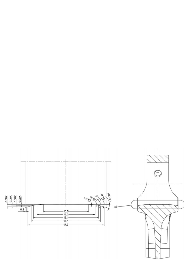
4.6.2 Geometry of the connecting rod small end
Surface pressure, as a dimension for the bearing load in the small end bore, is derived from
the gas pressure, pin diameter, and bearing width. It is generally greater than 100 MPa.
Gas pressure, as the highest magnitude load, acts only in the direction of the crank end bore,
which has led to the development of various types of support in the small end bore to meet
requirements relating to capacity, weight, and cost.
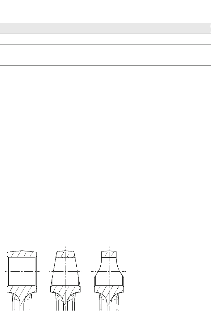
The parallel connecting rod is the basic version and the easiest to manufacture. It is the
most economical for manufacturing if the crank end has the same width as the small end
(Figure 4.8). Due to weight reduction requirements, this type is often replaced with one of the
variants described below, whereby the lower part of the small end bore, which is subjected to
the gas pressure, is wider than the upper part, which is subjected only to inertia forces.
Figure 4.8: Cross-sectional
shapes of the small end bore
Left: parallel connecting rod
Center: trapezoidal connecting rod
Right: stepped connecting rod
78 4 Connecting rod
The trapezoidal connecting rod is tapered at the small end and thus gets wider in the
direction of the connecting rod shank. The pin boss is adapted accordingly, in order to
reduce surface pressure here as well. During design, particular care must be taken as the
distance between the connecting rod and the pin boss in the direction of the piston pin axis
is reduced when the connecting rod pivots (Figure 4.8).
The stepped connecting rod presents the greatest challenge to the manufacturing pro-
cess. However, it best combines load carrying capability, mass reduction and hydrody-
namic conditions. During design, here again, it must be ensured that the connecting rod
does not collide with the piston when it pivots (Figure 4.8).
4.6.3 Bushing-less pin bearing in the small end
This solution reduces oscillating masses, which is of increasing importance in terms of
smooth running behavior and fuel consumption. Adequate lubrication of the small end bore
is essential for this concept. To improve tribological behavior, the small end bore contains a
profiled pin bore and may require a phosphate coating (Figure 4.9).
Figure 4.9: Shape optimization of the small end bore, without bushing
4.7 FE analysis of the connecting rod 79
necting rods for inline engines. The analysis
of connecting rods for V-engines depends
on the number of asymmetries present and
needs to be determined individually. The
assembled structure is fixed for the analysis
solely by means of contact boundary condi-
tions. Direct restraint of the connecting rod
structure is avoided because it would lead
to overconstraint of the conditions at the
restraint points. The assignment of material
properties concludes the modeling process.
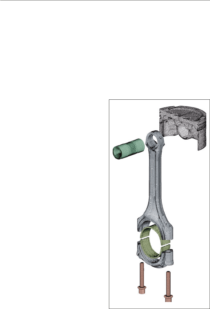
Figure 4.10:
Three-dimensional FE model of the connecting
rod of a passenger car gasoline engine with
bolts, bearings, and piston pin, as well as a sub-
stitute piston model for load application
4.7 FE analysis of the connecting rod
4.7.1 Modeling
The starting point of every FE analysis is modeling, i.e., the partitioning of the affected struc-
ture into many volume elements. The FE model includes, in addition to the pin end bore with
the cap, the bearings, bolts, and the piston pin, as well as a suitable replacement model for
the piston and the crankshaft (Figure 4.10). Modeling of all individual components is realized
as a three-dimensional structure including all significant details, with only minor simplifica-
tions (e.g., bolt threads). Symmetrical models can be used to limit the modeling effort for con-
80 4 Connecting rod
4.7.2 Stresses from assembly
The first load case is bolt pretensioning, which results from the assembly of the cap to the
connecting rod shank. A prerequisite for realistic determination of the resulting stresses is the
consideration of the geometry of the bolt shank, the parting line type (cracked or machined
parting line), the centering of the joint face, the bolt underhead contact face, thread depth
(number of load-bearing threads), and bearing crush.
4.7.2.1 Bolt force
Analogous to the specification for tightening the connecting rod bolts, the load on the bolt
joint is prescribed for the assembly simulation. In an iterative process, the extension and
thus the stress in the b
olt shaft is varied until the prescribed pretensioning force of the con-
nection has been reached. The yield point of the bolt material generally limits the amount of
pretensioning force. In some cases, however, the surface pressure on the cap in the area of
the bolt underhead contact face can be the limiting factor.
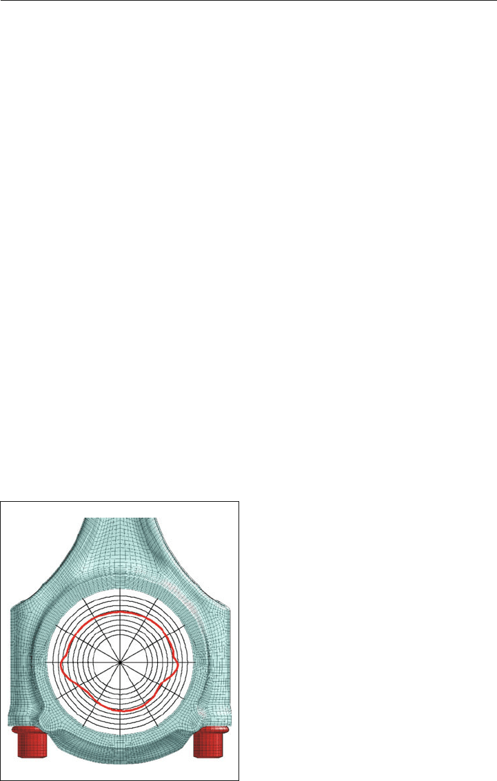
As a reaction to the bolt force, the crank end bore deforms into an out-of-round base bore
(Figure 4.11).
In the connecting rod manufacturing process, however, a perfectly round crank bore is gen-
erated during the finish machining by a properly applied bolt clamp load. It ensures ideal
geometry for this highly stressed bearing point. This manufacturing process is also recreated
in the simulation by a suitable procedure. This is necessary in order to prevent any disal-
lowed stress increases in the contact zones in the subsequent steps of representing the
operating loads.
Figure 4.11:
Representation of undesired deformation and
bulging of the crank end bore after connecting
rod bolts have been tightened

4.7 FE analysis of the connecting rod 81
4.7.2.2 Bushings, bearings, and shrink fit
For the typical plain bearing of the crank end bore on the crankshaft, split bearings with
defined crush are used for fixing and securing the position of the bearings during operation.
The bushing in the small end bore, or shrink-fit piston pin in the small end bore, generates
stresses due to interference. This interference in the bearings, piston pins, or bushings is rep-
resented in the simulation by appropriate contact boundary conditions. The resulting static
stresses are later combined with the dynamic stresses from operational loading.
4.7.3 Stresses from engine operation
It follows from the kinematics of the crankshaft drive that the piston, together with the small
end bore and the piston pin, performs an oscillating motion, and the crank end bore with
the crank journal on the crank throw primarily performs a rotating motion. The displacement
of the crank end bore leads to a pivoting motion of the connecting rod. The measure of the
pivot angle of the connecting rod is determined by the geometric dimensions of the crank
drive (crank radius and length of connecting rod).
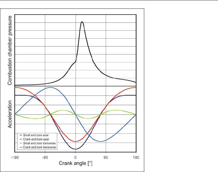
The pivot motion of the connecting rod leads to alternating transverse acceleration of both
the big and small ends, with an approximately sinusoidal curve (Figure 4.12). The vertical
motion of the connecting rod leads to a longitudinal acceleration, which also features a
modified sinusoidal curve. The stroke to the connecting rod center distance ratio (crank
radius to length of connecting rod) determines the degree of deviation from the sinusoidal
curve and leads to the acceleration at top dead center (TDC) being greater than that at the
bottom dead center. The two accelerations would be equal only in the case of an infinitely
long connecting rod.
In order to translate the dynamic operating loads on the connecting rod into suitable bound-
ary conditions for a static structural analysis, different load cases that can occur during one
or two crankshaft revolutions (depending on the working principle, 2- or 4-stroke) are cap-
tured and applied to the structure in the form of quasi-static boundary conditions.
N For the simulation of the load at TDC in the combustion cycle, the maximum of the com-
bustion chamber pressure is generally applied, so that a slight displacement of the gas
pressure maximum can occur, compared to the representation in Figure 4.12. The inertia
force directed opposite the gas pressure is taken into consideration, which counteracts
the combustion force to a degree.
N Only the inertia force, without any combustion chamber pressure, is therefore used accord-
ingly at TDC in the gas exchange cycle.
N In order to calculate the load due to transverse acceleration, the respective maximum from
the transverse acceleration curve for both the small end bore and the crank end bore
are applied in combination with the effective combustion chamber pressure at the cor-
responding point in time.
82 4 Connecting rod
The individual loads mentioned are combined appropriately to obtain a complete represen-
tation of the operating load. Ten relevant load cases are the result. Depending on the engine
type, there are different weightings of the individual load cases:
N For passenger car diesel engines, the gas pressure load on the connecting rod dominates,
whereas the load due to transverse acceleration is very small relative to the gas pressure
load and can be neglected.
N For passenger car gasoline engines, likewise, the gas pressure load on the connecting
rod dominates, while the load due to transverse acceleration is small for the typical speed
range (up to about 8000 rpm) and therefore negligible in general.
N For high-speed sport and racing engines, the inertia forces are essential and the loads due
to longitudinal and transverse acceleration are correspondingly high. Particularly at very
high speeds, the inertia forces can exceed the load due to gas pressure, and the greatest
load magnitude can result, for example, from the transverse acceleration.
4.7.3.1 Gas pressure
An example of the resulting comparative stresses on the connecting rod structure of a pas-
senger car gasoline engine, under combined assembly, gas pressure, and iner
tia forces at
rated speed at TDC of the combustion cycle, is shown in Figure 4.13.
Figure 4.12:
Plot of gas pressure and
inertia forces for a passenger
car gasoline engine in a four-
stroke combustion cycle