Mahle GmbH (Ed.) Cylinder Components: Properties, applications, materials
Подождите немного. Документ загружается.

104 5 Crankcase and cylinder liners
(Figure 5.8c). It is a variant of the piston alloy MAHLE 124 with a refined structure. The refine-
ment improves the mold filling behavior of the alloy, among other things, which is important
for casting very thin-walled fins. For less highly stressed finned cylinders made by pressure
die casting, the standardized alloy 226 (EN-AC 46000 per EN 1706) is employed.
For forged cylinder liners in motorsport engines, the piston alloy MAHLE 124P is used in
combination with a NIKASIL
®
surface coating (Figure 5.8d).
5.3.2.1 Effects of the casting process on the material properties of aluminum alloys
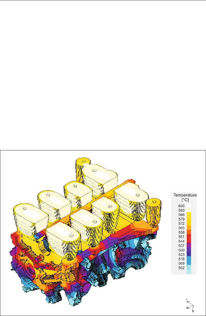
The local material properties of an aluminum engine block depend on the local form-filling
velocity, cross sections, and thus the local cooling speed during casting (
Figure 5.9).
Before creating a casting setup, MAHLE performs a casting simulation using a CFD program
to determine the following data in particular:
N defining a filling and solidification profile,
N liquid fraction of the melt,
N failure analysis,
Figure 5.9: Analysis of the solidification profile of a crankcase in the mold
5.3 Crankcase materials 105
N solidification time,
N dendrite spacing,
N not exceeding a maximum permissible porosity,
N optimization of cooling in the tool.
A projection of the residual stresses and local material properties is performed in a further
analysis, using a special analysis program.
5.3.2.2 Effects of heat treatment on the properties of cast aluminum alloys
Heat treatment of cast aluminum alloys serves to adjust the material properties. It must be
customized for each material and subsequent application.
One of the possibilities is annealing after casting. The soak time and temperature determine
the final mechanical proper
ties of the product.
Fatigue strength can be improved by hot isostatic pressing (HIP). In this process, the casting
is held in an inert gas atmosphere at high pressure and temperature prior to heat treatment.
The material is thus compacted and porosity is reduced.
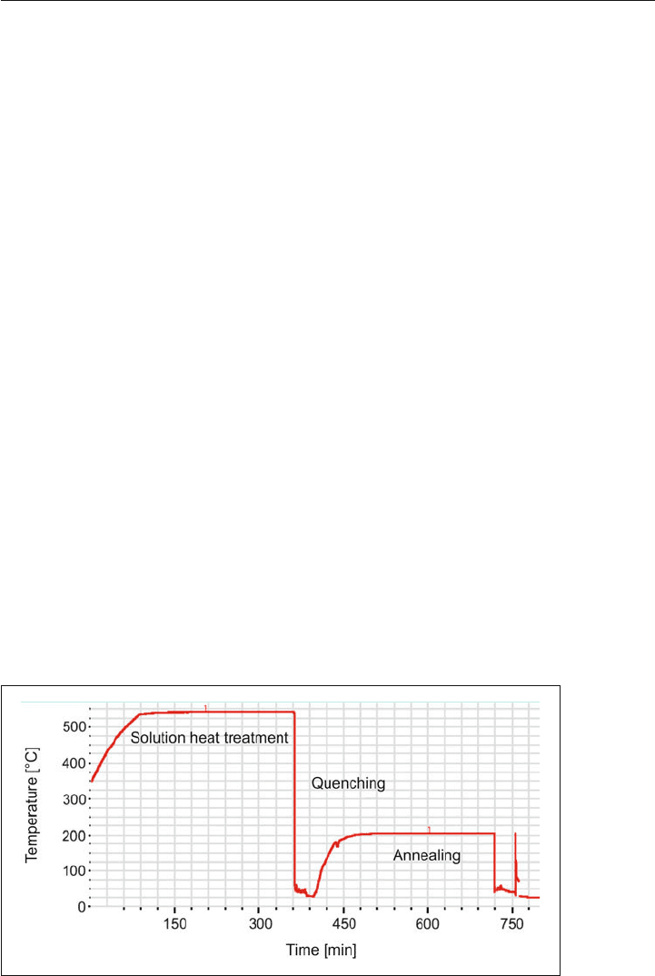
For sand castings, heat treatment can consist of a multi-stage cycle (Figure 5.10). During
solution heat treatment, the castings are soaked at a temperature just below the melting
point, at which the alloying components enter solution. The parts are then quenched. This
can, however, result in internal stresses in the component. A heat treatment process, also
known as annealing, follows.
Figure 5.10: Sample heat treatment curve of a sand casting made of an aluminum alloy

106 5 Crankcase and cylinder liners
5.3.3 Magnesium
Due to its density, 35% lower than that of aluminum, and its low Young’s modulus, magne-
sium is typically used for non-structural engine components. As a material for crankcases, it
has some disadvantages:
N increased tendency to creep at high temperatures,
N loss of pretensioning at higher temperatures when using steel bolts,
N tendency toward galvanic corrosion when in contact with steel,
N tendency to corrode when exposed to coolants.
One possible solution for reducing component weight is to produce highly stressed locations
in a hypereutectic aluminum alloy, which are then encapsulated with magnesium. With a
hybridized combination of magnesium and aluminum, weight savings in such a component
can be up to 25%.
5.3.4 Material trends
The trend toward ever higher power-to-weight ratios requires new materials. This applies
first to passenger car diesel engines with cylinder pressures of up to 200 bar, which consti-
tutes the performance limit for the use of aluminum crankcases. For less stressed engines,
such as gasoline engines, aluminum will remain dominant, except for cases where cost is
a significant factor or where high-performance derivatives are sought. Magnesium will find
only limited application due to its lower high-temperature stability and tendency to creep, its
corrosive behavior, and its higher cost.
5.3.5 Effects of the casting process on the design of the
crankcase
The technical requirements and tools required, and therefore the costs, have a significant
effect on the selection of the casting process. This decision is generally made prior to the
first draft of the component. It is therefore important to be aware of the advantages and
disadvantages of the various casting processes. Some of the typical casting processes and
their associated designs are shown below.
5.3.5.1 Sand casting
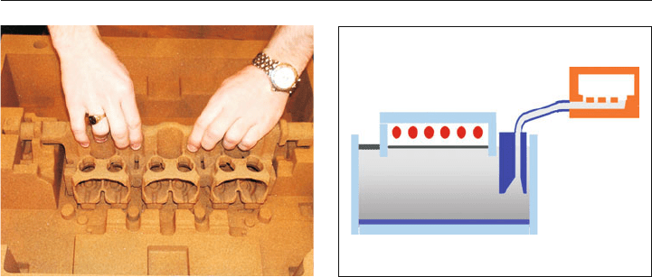
Sand casting parts are cast in a sand mold with sand cores inserted. These can be indi-
vidual cores or core packages (Figure 5.1
1). The molten metal is either cast-in from above or
5.3 Crankcase materials 107
pumped into the mold from below. Figure 5.12 shows a mold with mold filling from below.
The cores are generally manufactured out of sand or in a CPS process (core package sand
process).
5.3.5.2 COSCAST
TM
method
One variant of the sand casting process is the patented COSCAST
TM
method, in which cores
are made from zirconium sand. This material provides precision castings with high surface
quality, due to its shape accuracy. The aluminum melt is filled into the mold from below using
a ceramic pump; it is then rotated 180° for solidification. The process is particularly suited for
small and medium batches.
5.3.5.3 Molding sand—“green sand”
Sand cores made of molding sand are bonded with clay or mud and have a relatively high
moisture content. The moisture is absorbed by the aluminum during casting and causes
a cer
tain porosity in the die-cast part, which is associated with an undesired reduction in
mechanical strength. This process is not always suitable for series production, despite its
cost advantages.
5.3.5.4 CPS method
In this method, the sand core is chemically bonded with resin, for example. The binder is then
hardened in an oven, or by infiltration with gas, or even just at room temperature, depending
on the type. Silicon or zirconium sands are used. Zirconium has a very small thermal expan-
sion coefficient and density similar to that of aluminum. Cores made of zirconium sand are
used preferably for die-cast par
ts with high dimensional accuracy, for complex cores, and for
high mechanical strength requirements.
Figure 5.11: Inserting a core package in a mold
Figure 5.12: Principle of a mold with filling from
below

108 5 Crankcase and cylinder liners
The principle advantages of sand casting for crankcases are the possibilities of:
N incorporating oil and other galleries as well as cooling jackets in the casting,
N casting bores and recesses (weight savings),
N improving material properties with heat treatment.
The principal disadvantages of this process are the high investment costs required for mass
production (short production times) and difficult cooling of critical areas. The lack of cooling
capability makes it more difficult to cast hypereutectic alloys.
5.3.5.5 Full-mold casting method (lost foam method)
Cores are made of polystyrene foam, given a heat-resistant coating, and placed in the mold.
When the liquid metal is poured in, the foam is gasified.
Complex crankcases with a high number of integrated accessories can be manufactured
at a reasonable cost using cores of this type. The ability to integrate cooling galleries is lim-
ited, however
, so it can be difficult to reliably achieve the required cooling speed at critical
points.
5.3.5.6 Permanent mold casting
In permanent mold casting, reusable molds and cores are used and the metal is cast into
the mold under pressure.
The characteristics of this process are high dimensional accuracy
, very good surfaces, and
high tooling costs. Crankcases are generally manufactured in permanent molds at medium
to high production quantities.
5.3.5.7 Gravity die casting
The molten aluminum is filled into the mold under the influence of gravity. Due to the low
filling pressure, lost sand cores can even be used, and only very low turbulence occurs.
Dimensional accuracy is good. T
he local material structure can be improved, if needed, with
targeted cooling. The material properties can also be stabilized with targeted heat treatment,
such as solution heat treatment, quenching, and annealing (Section 5.3.2.2).
5.3.5.8 Low-pressure die casting
Filling the mold under controlled pressure opens up a few advantages compared to normal
gravity die casting. By controlling the filling speed, better mechanical properties can be
obtained, and by maintaining pressure during the solidification process, the porosity of the
par
t can be controlled in a targeted manner.

5.4 Cylinder liners and cylinder surfaces 109
5.3.5.9 Pressure die casting
The aluminum is filled into the mold under high pressure. High pressure and rapid filling
allow the casting of thin-walled parts, improvement of material properties with intensive
cooling, and short cycle times. The disadvantage is that the use of insert parts is limited
and expensive because the risk of absorption of gases, and thus porosity, is increased, and
subsequent heat treatment is not possible without degassing the mold.
5.3.5.10 Squeeze casting
Compared to “simple” pressure die casting, as described in Section 5.3.5.9, the melt is filled
into the mold from below through a riser at low speed. High pressure is maintained during
the solidification process with this method as well. Crankcases are preferably cast vertically
in this process, which allows more effective degassing during the filling process and thus
reduces gas inclusions. Subsequent heat treatment is used to obtain improved material
proper
ties. The required wall thicknesses for this process are generally somewhat greater
than for pressure die casting.
5.3.5.11 Semi-solid method
A newly developed casting process for manufacturing crankcases processes aluminum in
a semi-solid (thixotropic/rheotropic
) state. In this process, the aluminum is heated to the
appropriate temperature and then injected into the mold under high pressure. For thixotro-
pic casting, the aluminum billets with non-dendritic structures are inductively heated to the
appropriate temperature and then injected into the mold. For rheotropic casting, the liquid
metal is cooled to the semi-liquid phase, in which no dendrites have yet formed, and then
injected into the mold. Both processes prevent air inclusions, feature low shrinkage and
short solidification times, form fine-grained structures, and provide the capability of improv-
ing material properties through further heat treatment.
5.4 Cylinder liners and cylinder surfaces
5.4.1 Requirements for the cylinder surface
Due to the axial motion of the piston and piston rings, their partner, the cylinder surface, is
subjected to wear as well. Wear occurs particularly at the upper reversal point of the piston
rings because the change in direction of the moving parts limits the lubrication. The wear
behavior of the running surface and the piston rings is substantially determined by the mate-

110 5 Crankcase and cylinder liners
rial pairing selected for the two components. In order to reduce wear, the running surface
should be smooth and the lubrication between the sliding partners must be ensured. The
type and quality of the running surface effects oil consumption as well as the wear of the
two components.
5.4.2 Cylinder surfaces in aluminum crankcases
The monolithic aluminum crankcase is based on a hypereutectic AlSi alloy (such as AlSi17),
whereas the cylinder surfaces are produced by chemical etching or mechanical exposure
(special honing) of the primary silicon crystals. The disintegration rate of the silicon crystals
must not exceed an upper limit for both processes.
For quasi-monolithic crankcases, the bores are coated, for example, with a galvanic MAHLE
NIKASIL
®
layer (Figure 5.27) or plasma thermal spraying. Alternatively, cylinder surfaces can
be produced with local material engineering, by laser alloying (e.g., with silicon) or by using
Al matrix composite materials (preforms) with subsequent finishing.
The dominant design, however, is the heterogeneous crankcase, in which cast-in or inserted
cylinder liners made of GJL form the cylinder surfaces.
In addition to the general requirements for cylinder surfaces, additional conditions must be
met when using cylinder liners. The wall thickness and material strength must be sufficient,
so that the cylinder liners do not crack. The finite element analysis allows the design and
material selection to be adapted to the loads due to assembly, temperature, peak cylinder
pressure, and piston side forces. Stresses originating from assembly are essentially deter-
mined by the number, tightening torque, and arrangement of cylinder head bolts as well as
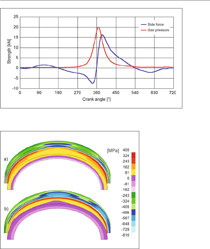
the selected cylinder head gasket. Figure 5.13 shows a typical gas pressure and side force
curve as a function of the crank angle. The maximum side force occurs after the maximum
gas pressure, while the side force acts transverse to the pin axis only in the piston contact
area.
Based on temperature distribution, side forces and bolt arrangement, the loads on the
liners, as well as stresses and deformations vary around the circumference. In Figure 5.14,
using the example of the bottom side of the flange of a cylinder liner, the resultant stresses
for the load case of assembly and temperature and the superposition of all load cases at
maximum side force are depicted. The maximum stress occurs in the area of the radius of
the liner flange, which is in contact with the crankcase. Using fatigue strength charts, the
effects of changes in design and material on the local safety factor are evaluated.
5.4 Cylinder liners and cylinder surfaces 111
5.4.3 Types of cylinder liners
The design of the cylinder liner is based, among other things, on the area of application of
the engine.
For passenger car engines, cylinder liners are predominantly cast into aluminum crankcases.
Replaceability of the cylinder liner does not seem to be necessary due to the relatively low
service life of these engines.
Figure 5.13: Gas pressure and side force as a function of the crank angle
Figure 5.14:
Maximum stresses at the
bottom side of the flange of a
cylinder liner, for load cases:
a) assembly + temperature +
max. side force + gas
pressure
b) assembly + temperature
112 5 Crankcase and cylinder liners
To obtain an interlocking connection during casting, the outer surface of the cylinder liner
is grooved, such as by machining (Figure 5.15a). So-called rough cast liners are cast with a
rough surface (Figure 5.15b). Rough cast liners provide excellent heat transfer from the com-
bustion chamber and cylinder chamber, due to their tight engagement with the crankcase.
A light metal alloy coating on the external surface of these cylinder liners is also possible in
order to improve the bonding to the case material.
The geometric design of the cylinder liners is to be adapted to the installation space of the
engine and to the casting process. The cylinder liners are finely bored and honed in the
crankcase (Section 5.4.5). The remaining load-bearing residual wall thickness for rough cast
liners made of gray cast iron should be no less than 1–1.5 mm. The wall thickness depends
on the permissible land width between the cylinder liners, the roughness depth on the out-
side diameter, and offsets during casting.
When used in pressure die-cast cases, roughness depths of about 1.5 mm can be used for
rough cast liners. When casting in a gravity die casting process, the roughness depth should
not exceed 1 mm. For the land spacing between two cylinder liners, different limit dimensions
apply depending on the casting method (gravity die casting, pressure die casting with single
or double gating).
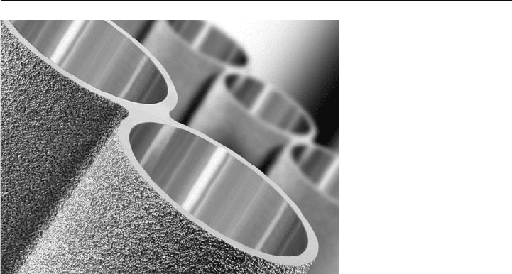
In addition to the typical rough cast liners made of cast iron, MAHLE has also developed
a rough cast liner made of a hypereutectic aluminum-silicon alloy. The ALBOND
®
liner is a
composite of several cylinders, based on an aluminum alloy (Figure 5.16). This liner compos-
Figure 5.15:
Cast-in liners for light-alloy
housing:
a) grooved cylinder liner
b) rough cast liner
a)
b)
5.4 Cylinder liners and cylinder surfaces 113
ite simplifies handling and allows very tight cylinder spacing, even if cross drillings are to be
incorporated between the cylinders.
In the case of large bore engines for power generation or commercial vehicle engines, the
running surface wears relatively severely due to high cylinder service life. Because the service
life of these engines is generally much greater than for passenger car engines, replaceable
cylinder liners made of suitable materials are generally used (Section 5.4.4).
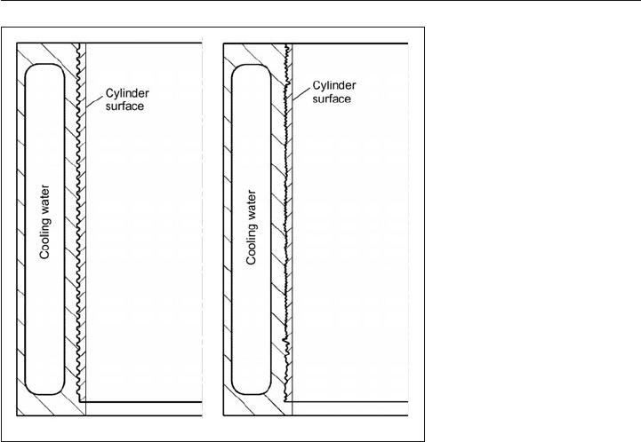
For the cylinder liners used in the crankcase, a differentiation is made between “dry” and
“wet” liners.
Dry cylinder liners made of cast iron have relatively thin walls at 1.5–4 mm. This means that
they take up only little installation space, but are not in direct contact with the coolant (Figure
5.17). Precise matching of installation clearances between the crankcase and the cylinder
liner is necessary. This prevents stress peaks that can cause cracks.
The axial location of replaceable cylinder liners is determined by a flange, generally on the
top side. Dry cylinder liners are mounted with a press or interference fit (Figure 5.17a) or a
transition fit (e.g., H7/n6) (Figure 5.17b) in the crankcase. Cylinder liners with interference fits
are finish machined only after being installed in the crankcase.
Cylinder liners with interference fits feature better heat transfer to the crankcase. This solution
is selected, for example, when gray cast iron liners are installed in aluminum crankcases. Good
heat transfer is ensured, however, only if the interference exists at all operating temperatures
present in the aluminum case. Fits similar to ISO fits N7/r6 (interference ~ 0.05–0.10 mm)
can be used for installation here or, for engines with increased operating temperatures, R7/r6
(interference ~ 0.075–0.125 mm). These interference fits make it necessary, as a rule, to cool
the cylinder liners with liquid nitrogen or to heat the crankcase prior to assembly.
Figure 5.16:
ALBOND
®
cylinder liner com-
posite with rough surface