Mahle GmbH (Ed.) Cylinder Components: Properties, applications, materials
Подождите немного. Документ загружается.

4.7 FE analysis of the connecting rod 83
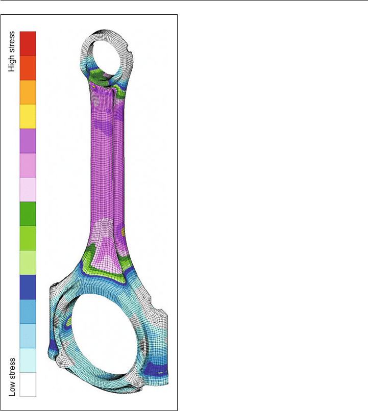
High stress can be detected on the connecting rod shank. The location with the minimum
cross section establishes the limits of pure compressive capacity. Analyses of the buckling
resistance of the connecting rod shank must also be carried out, as the maximum capacity
can be further reduced if the buckling resistance is not sufficient. Other locations with high
static loading are the areas of fastener pre-loading. The local material creeping that typi-
cally results in the bolt thread and in the bolt head contact area leads to redistribution and
smoothing of the load. Due to the pulsating gas pressure load, the transitions from the con-
necting rod shank to the large and small end bores are dynamically highly loaded locations.
The limits of endurance of the connecting rod, in terms of service life, ultimately result from
this consideration.
Fr 4.13:
Comparative stresses on the connecting rod
structure of a passenger car gasoline engine
under combined assembly, gas pressure, and
inertia forces at rated speed at TDC of the com-
bustion cycle
84 4 Connecting rod
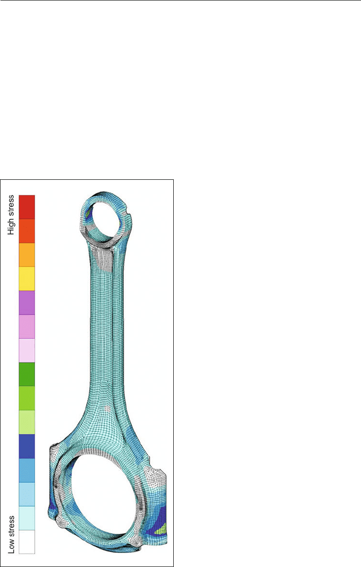
4.7.3.2 Inertia force
The comparative stresses on the connecting rod structure of a passenger car gasoline
engine, under combined assembly and inertia forces at rated speed at TDC during the
exhaust stroke, is shown in Figure 4.14.
Dynamically highly loaded locations from alternating inertia force loads, once again, are the
transitions from the connecting rod shank to the big and small end bores. The effect of the
inertia force in the gas exchange stroke leads to an oval deformation of the connecting rod
bores. The resulting wipping load must be borne by the structure at the small end bore and
by the bolted joint at the big end bore. In addition to the requirements in terms of operational
durability, the effects on bearing clearance play a primary role. To limit deformations, larger
cross sections may be required than would otherwise be necessary for strength reasons
Figure 4.14:
Comparative stresses on the connecting rod
structure of a passenger car gasoline engine
under combined assembly, gas pressure, and
inertia forces at rated speed at TDC during the
exhaust stroke
to ensure fatigue resistance. Greater bear-
ing eccentricity may also be called for (ref.
Section 3.3.4.1).
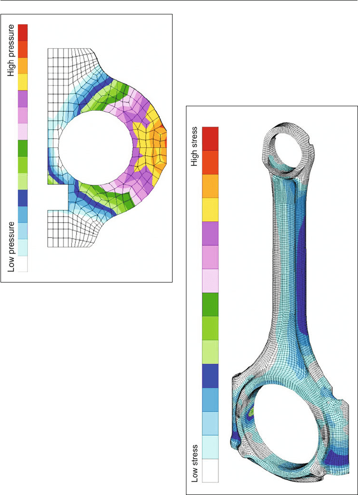
As a further aspect, dynamic gap open-
ing of the parting line at the big end must
be investigated for minimum bolt force
and maximum inertia force at TDC during
the exhaust stroke. Gap opening must not
occur, or has to be minimal, in edge areas,
i.e., surface pressure must not reach zero.
See Figure 4.15. Otherwise, suitable mea-
sures to increase surface pressure are
needed, such as greater bolt clamp load or
a reduced parting line surface area.
4.7 FE analysis of the connecting rod 85
Figure 4.15:
Surface pressure distribution for investigation
of gap opening in the parting line of the big end
at maximum inertia force loading at TDC during
the exhaust stroke
Figure 4.16:
Comparative stresses in the connecting rod
structure under combined assembly, gas pres-
sure, and inertia force loads at rated speed at
the point of maximum transverse acceleration of
the big end
Figure 4.16 shows the comparative stresses
in the connecting rod structure of a series
passenger car gasoline engine under com-
bined assembly, gas pressure, and inertia
force loads at the rated speed, at the point of
maximum transverse acceleration of the big
end. This results in only minor bending loads
on the connecting rod shank. Bending loads
on the connecting rod shank resulting from
the maximum transverse acceleration at the
small end are even lower. Since the maxi-
mum transverse acceleration at the small
end occurs in an early crank angle range,
near the combustion and gas exchange
stroke TDC, the longitudinal load on the
structure due to gas pressure dominates
once again. It should be noted, however,
that these statements apply exclusively to
normal operating speeds for series engines

86 4 Connecting rod
(up to about 8,000 rpm for gasoline and 5,000 rpm for diesel), but not for the very high
engine speeds of racing engines (up to about 20,000 rpm). The greater the engine speed
level, the more dominant the loads due to inertia forces come to be, until finally they become
the largest operating load on the connecting rod.
4.8 Component testing of the connecting rod
Connecting rods, like all other components of an internal combustion engine, must reliably
bear the highest loads that can occur during operation. These occur over the entire engine
speed range when operating under full load.
Testing of component and operational strength is intended to demonstrate that, even con-
sidering variability in material strength and the manufacturing process (blank, machining,
surface treatment, assembly, etc.), the component meets all strength requirements.
The primary stress in tension and compression due to the oscillating inertia force and gas
pressure occurs in the axial direction of the connecting rod shank (connecting rod load F
St
).
For high-speed engines, the bending stresses occurring in the plane of motion of the con-
necting rod, arising from the rotating masses, must not be neglected.
Additional, not insignificant bending moments can act on the connecting rod due to man-
ufacturing tolerances, installation conditions, and deformations of the crankshaft and the
crankcase.
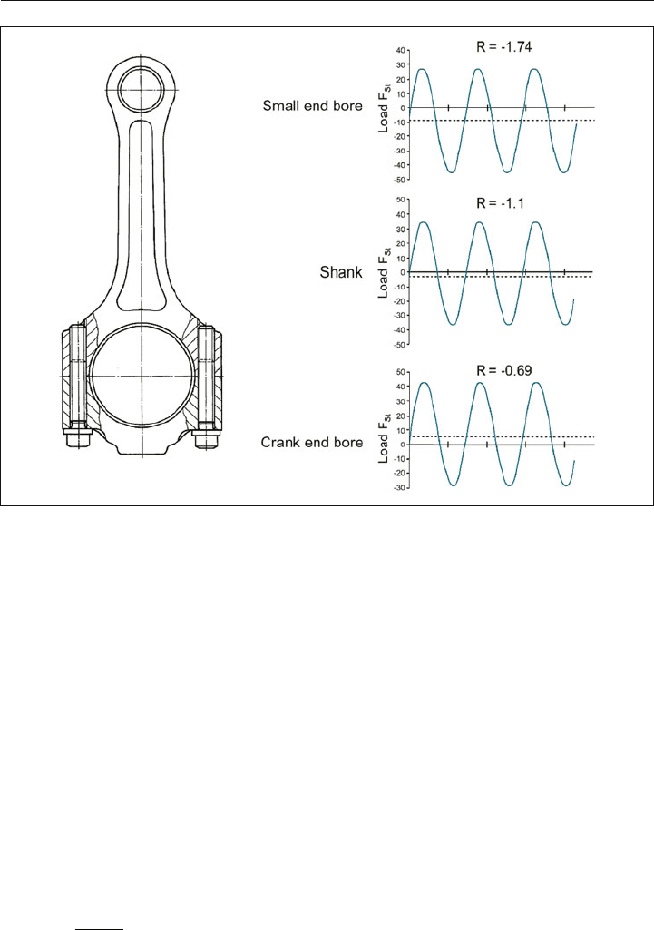
Typically, component testing of the connecting rod under alternating tension/compression
loads is performed on resonance pulsators or servohydraulic testing machines. When deter-
mining the load cases, it must be taken into consideration that due to mass distribution over
the length of the connecting rod, different load conditions R (R = underload/overload) and
thus different average stresses can arise during engine operation (Figure 4.17).
When determining boundary conditions, execution, evaluation, and statistical evaluation of
component tests of this type, engine manufacturers have different procedures, based on
longstanding experience.
The maximum value occurring during the combustion cycle is always used for the gas pres-
sure. The inertia force has different values, depending on the engine speed. At MAHLE, the
pulsator tests are always carried out using the highest resulting values. This means that the
load amplitudes applied in the pulsator test are made up of values that do not occur at the
same engine speed.
4.8 Component testing of the connecting rod 87
Figure 4.17: Pulsator testing of a connecting rod (R: load ratio; F
St
: connecting rod load)
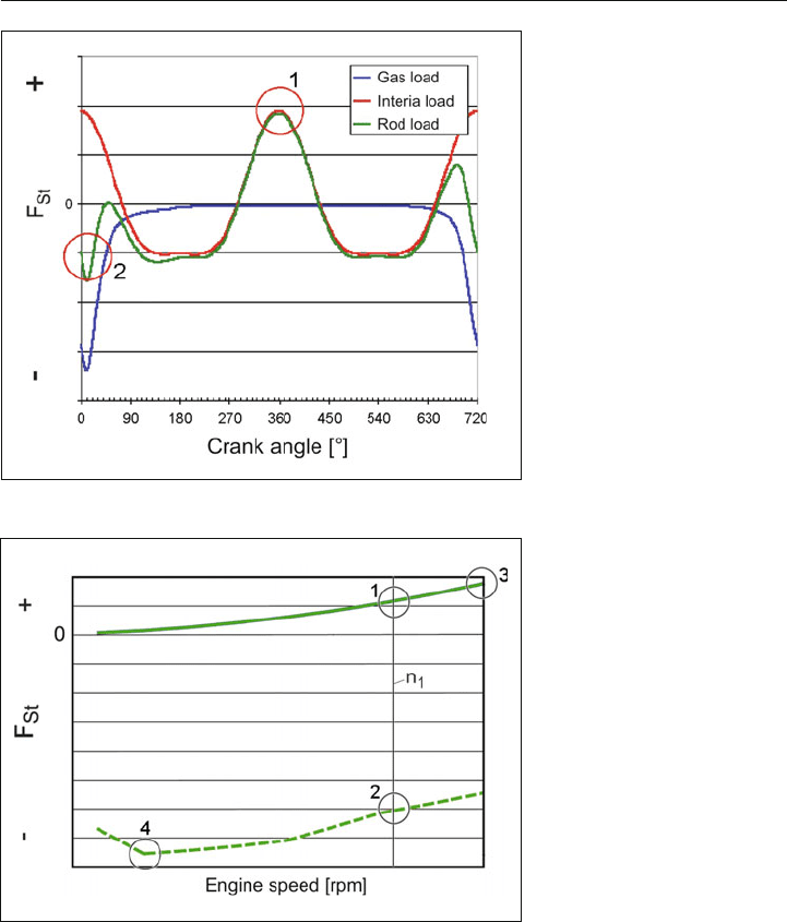
The required data are determined in that, analogous to Figure 4.18, the curve of gas load
(blue) and inertia load (red) is calculated for different engine speeds, in this case for a four-
stroke engine. The resulting sum curve (green), which represents the rod load (F
St
) curve,
yields maximum and minimum, which are marked here as points 1 and 2. These are shown
in the diagram in Figure 4.19 as a function of the engine speed. It shows the curve for maxi-
mum inertia load (upper curve) and maximum gas load (lower curve), where points 3 and 4
indicate the largest value F
St max
and the smallest value F
St min
of the rod load F
St
.
The following applies for the pulsator tests:
FFF
a Stmax Stmin
05.( )
Load amplitude (4-1)
FFF
m Stmax Stmin
05.( )
Mean load (4-2)
L
oad ratio (4-3)
R
F
F
Stmin
Stmax
88 4 Connecting rod
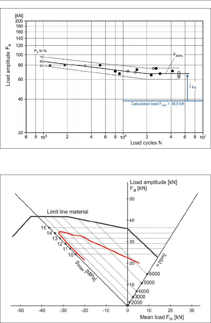
The staircase method has been proven for rapid and cost-effective determination of the S-N
curve (Figure 4.20). Using a load amplitude near the expected median of the transition range,
the first sample is tested. If the sample does not fracture, then the load for the next sample
is increased with a constant step width, until fracture occurs. The load is then reduced step-
wise until no further fracture occurs. The method very quickly centers on the average value.
A clear combination of the load map in the engine, with lab results of component durability
is shown in the Haigh diagram (Figure 4.21).
Figure 4.19:
Rod forces in a connecting
rod as a function of engine
speed
Figure 4.18:
Calculated rod loads in a con-
necting rod over a combus-
tion cycle of 720 degrees
of angle at constant engine
speed, such as n
1
4.8 Component testing of the connecting rod 89
Figure 4.20: Component S-N curve for a connecting rod, determined according to the staircase
method (P
ü
: probability of survival at 10, 50, 90%, F
D50%
: average endurance strength, P
ü
: 50%)
Figure 4.21: Operating loads on a connecting rod in a Haigh diagram

90 4 Connecting rod
The safety factor j is determined from the quotients of
(4-4)
j
Durability
Operating loads
The required minimum value is dependent, among other things, on the required survival
probability, the standard deviation, the targeted probability of failure, and the area of applica-
tion.
In addition to the pulsator tests already described, special fix
tures are used by engine manu-
facturers to apply, for example, wipping loads. Engine tests are also carried out at engine
overspeed on a short block, using an external drive.
4.9 Steel grades for forged connecting rods
In the past, heat-treated steels were primarily used for connecting rods. In the 1980s, these
were increasingly replaced with precipitation-hardening ferritic-perlitic steels, or AFP steels
for short.
With the development of the fracture splitting method (Section 4.4.1), the steel grade C70S6BY
was introduced in the mid-1990s as a standard material for connecting rods. This material is
air-cooled immediately after hot forging, like an AFP steel, and has the typical advantages of
these steels, such as the elimination of additional heat treatment, low distortion, cost-effective
machinability, and the required fracture splitting ability, see page 75. The structure is nearly
perlitic, with a small ferrite portion at grain boundaries. The high perlite portion supports the
formation of brittle fracture surfaces during cracking, which provide an exact fit between the
upper and lower parts due to their crystalline fracture microstructure.
As a reaction to the increasing combustion pressures in engine design, a new, high-strength
forging steel has been developed: 36MnVS4BY. This steel provides a higher yield point and
improved ductility (see page 75), which enables an increase in the design strength of com-
ponents of up to 30% compared to C70S6BY. These improved mechanical properties have
been achieved by increasing the vanadium content and thus the associated precipitation-
hardening that is typical of AFP steels. It is characterized by the formation of finely dis-
tributed vanadium-carbonitride precipitation during cooling of the forging from the heat of
deformation. The microstructure is ferritic-perlitic and the ferrite portion is greater than that
of C70S6BY, due to the lower carbon content. Machinability is significantly improved in com-
parison to C70S6BY.

4.10 Connecting rod bolted joint 91
4.10 Connecting rod bolted joint
4.10.1 Requirements for connecting rod bolted joint
The connection of the conrod cap to the connecting rod shank is a typical example of a
dynamically and eccentrically loaded bolt joint. It transfers inertia forces from the piston,
piston rings, piston pin, and connecting rod to the crank journal. In the process, the forces
must be guided around the crank journal. Therefore, in addition to axial loads, transverse
forces and bending moments act on the bolt joint. Additionally, due to gas pressures in the
combustion chamber, deformations occur in the crank end bore, which causes additional
transverse forces in the parting line, particularly for connecting rods with a crank end bore
that is split at an angle. These boundary conditions lead to dynamic stress in the connect-
ing rod bolts in the longitudinal and transverse directions. To reliably support these stresses,
high clamping forces are required.
In addition, the bolt joint has to support the forces for fixing the bearings. The force required
to generate the interference from the bearing crush must also be considered in the analysis
of the pretensioning force of the connecting rod bolts.
Variations in the pretensioning force must be small, because otherwise undesired shape
deviations can occur in the connecting rod big end. The stress state during machining of the
bearing shell housing, and later during connecting rod assembly in the engine, must there-
fore be nearly identical, because otherwise the different bolt forces can cause deviations in
the roundness of the housing that negatively affect the function of the bearing.
This makes it necessary to use bolts with high material strength and assembly methods that
take as much advantage of the material as possible, up to the yield point, such as the torque
plus angle method or yield point method. For bolts that are tightened beyond the yield point,
the permissible number of times they can be tightened is limited. In some cases, new bolts
must be used for repeated assembly.
4.10.2 Design and analysis of connecting rod bolted joint
The design of the connecting rod bolted joint is made on the basis of guideline VDI 2230. It
provides general instructions for the analysis of a bolted joint. The derivation of the operat-
ing forces on the bolt joint, which result primarily from the inertia force loading due to the
masses of the power cell unit, are not included in this guideline.
Using an analysis method for a closed circular ring model (big end bore), the relevant oper-
ating loads (lateral force, transverse force, and bending moment) can be determined in the
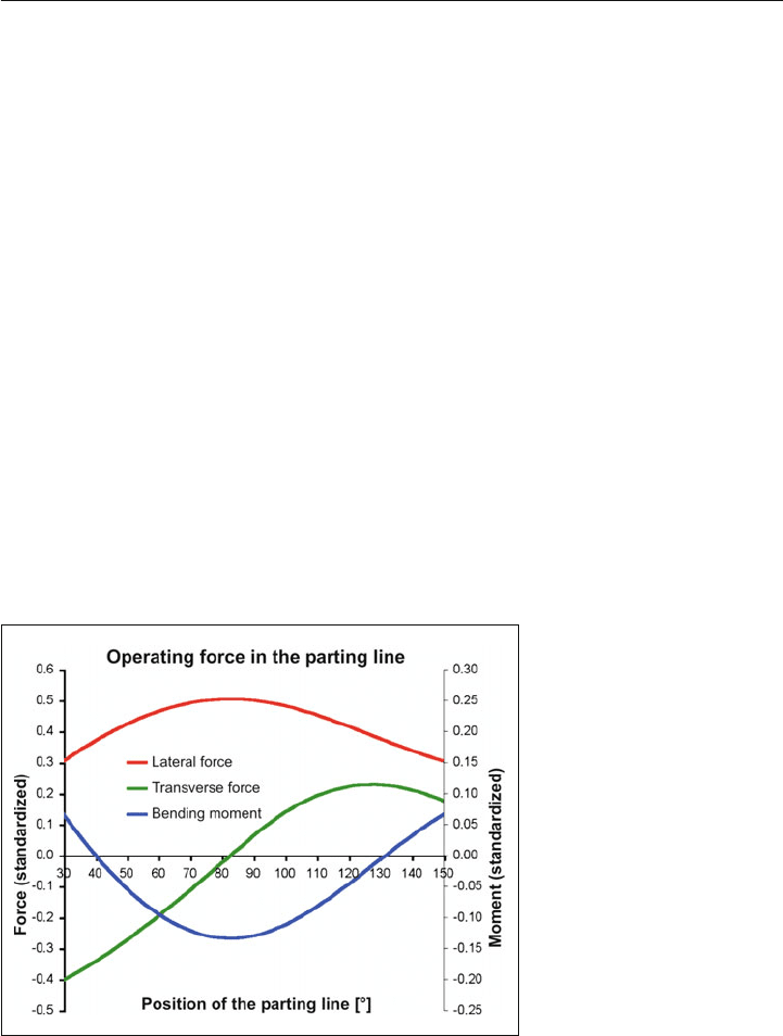
92 4 Connecting rod
parting area of the big end bore. The calculation of the stresses in the bolted joint uses the
maximum tensile load, which is defined in the connecting rod direction by the inertia force
at TDC.
Starting from the operating load (lateral and transverse force, bending moment), the sys-
tematic calculation steps can be carried out on the basis of guideline VDI 2230. The elastic
compliances of the bolts and tensioned parts (stepped bending bodies) are determined and
the operationally reliable function of the bolt joint is demonstrated.
The results are:
N bolt pretensioning force due to assembly (min., max.) for yield point tightening or torque
plus angle tightening (plastic deformation),
N tightening torque (min., max.),
N surface pressure on the bolt underhead contact face,
N required clamping force/bolt pretensioning force to prevent partial gap opening of the
parting line, considering the clamping force of the bearings,
N operating force/engine speed at the start of gap opening in the parting line,
N demonstration of durability, stress amplitude (including bending) at the threads, even for
the case of partial gap opening at the parting line,
N required minimum engagement length of the thread (nut height).
Figure 4.22:
Calculated forces in the par-
ting plane of the crank end
4.10.3 Shape of the connecting rod bolts
The connecting rod bolt joint can be designed as a through hole or blind hole, which has a
reduced notch effect. The through hole with threaded bolts and nuts on either side, or with