Lyons W.C. (ed.). Standard handbook of petroleum and natural gas engineering.2001- Volume 1
Подождите немного. Документ загружается.

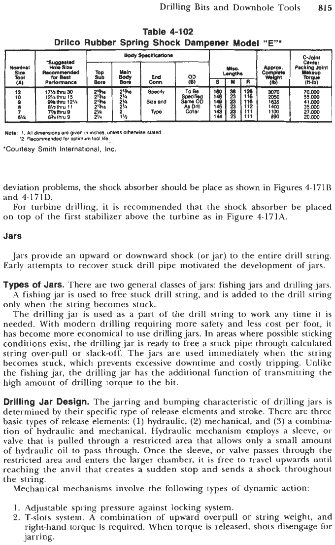
Drilling Bits and Downhole Tools
815
Nomlnal
sln
Tool
(A)
12
10
8
7
6%
Sp.cn1-m
CJolnt
'Sugg..l.d
.
C.mr
Makaup
HobSlt.
RacomNndad
iM
0m.t
OD
R-lb)
Pmrformance
Bar.
17YlmrU30
2'h
2'910 Spec@
TO80
160
30
120
3070
70.000
SpecifW 148
23
116
2OXI
55.000
12hlhru 15 2% 2'14
athru 12V4
2% 2'4
Sizeand
SameOD
149
23
110 1635 41.000
BMlhru 11
2'sis
2'14 AsDrill 145
23
112 1400
35.m
Collar
143
23
111 1100 27.000
144
23
111
890
2c.m
mmrus
2v4
2
Type
6%.
thru
9
2'/.
1
'h
Nota
1
All
dimensions
are given
in
Inches. unless otherwse staled
'2 Recommended
lor
optimum
IwI
life
'Courtesy
Smith
International, Inc
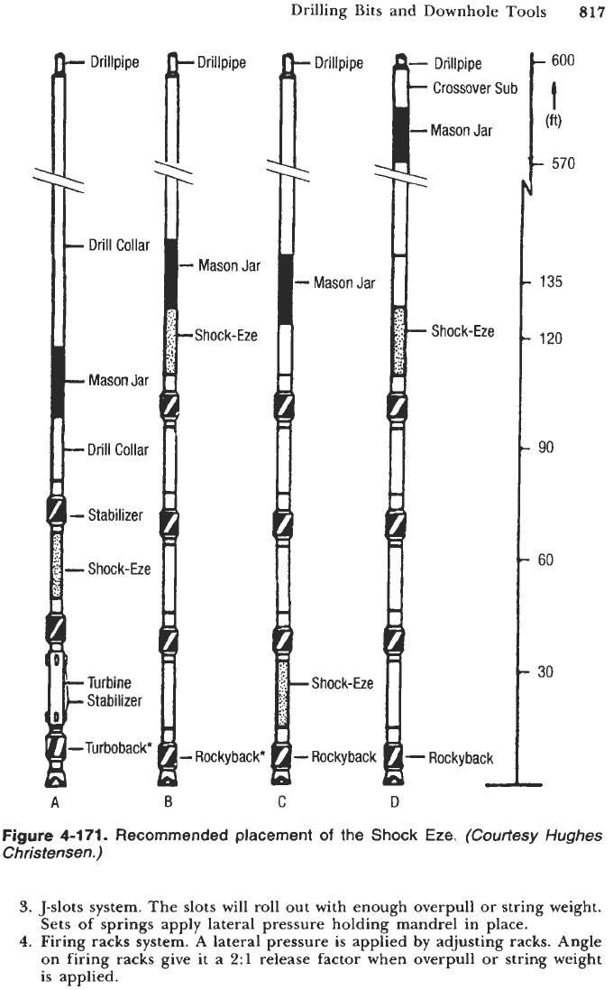
deviation problems, the shock absorber should be place as shown in Figures 4-171B
and 4-171D.
For turbine drilling, it is recommended that the shock absorber be placed
on top of the first stabilizer above the turbine as in Figure 4-171A.
Jars
Jars provide an upward or downward shock (or jar) to the entire drill string.
Early attempts to recover stuck drill pipe motivated the development of jars.
Types of Jars.
There are two general classes of jars: fishing jars and drilling jars.
A
fishing jar
is
used to free stuck drill string, and is added to the drill string
only when the string becomes stuck.
The drilling jar
is
used as a part of the drill string to work any time
it
is
needed. With modern drilling requiring more safety and less cost per foot,
it
has become more economical to use drilling jars. In areas where possible sticking
conditions exist, the drilling jar is ready to free a stuck pipe through calculated
string over-pull or slack-off. The jars are used immediately when the string
becomes stuck, which prevents excessive downtime and costly tripping. Unlike
the fishing jar, the drilling jar has the additional function of transmitting the
high amount of drilling torque to the bit.
Drilling Jar Design.
The jarring and bumping characteristic
of
drilling jars
is
determined by their specific type of release elements and stroke. There are three
basic types of release elements:
(1)
hydraulic,
(2)
mechanical, and
(3)
a combina-
tion of hydraulic and mechanical. Hydraulic mechanism employs a sleeve, or
valve that is pulled through a restricted area that allows only a small amount
of hydraulic oil to pass through. Once the sleeve, or valve passes through the
restricted area and enters the larger chamber,
it
is
free to travel upwards until
reaching the anvil that creates a sudden stop and sends a shock throughout
the string.
Mechanical mechanisms involve the following types of dynamic action:
1.
Adjustable spring pressure against locking system.
2.
T-slots system. A combination of upward overpull or string weight, and
right-hand torque is required. When torque is released, shots disengage for
jarring.
816
Drilling ai
nd
Well
Completions
MALE SPLINE
SAL
CAP
SPLINE
INSERT
FEMALE
SPLINE
MANDREL
1
80WL
BEL LEWLLE
SFWINGS
MAWEL
2
CIXVPBVSATlNG
PISTaV
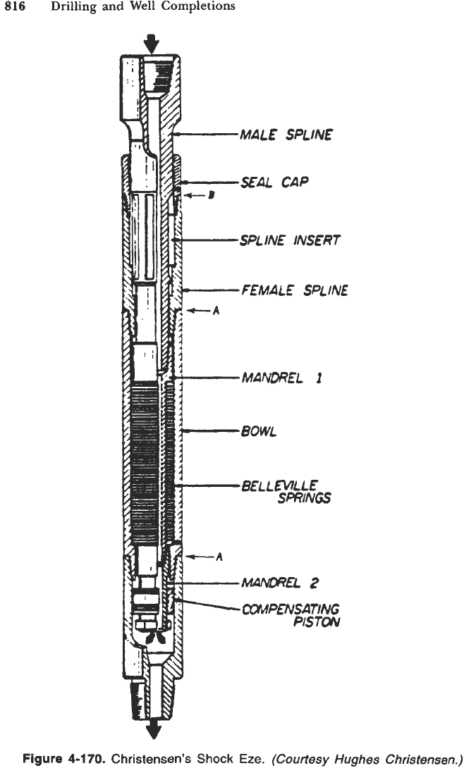
Figure
4-170.
Christensen’s
Shock
Eze.
(Courtesy
Hughes
Christensen.)
Drilling
Bits
and Downhole Tools
817
A
B
C
D
Figure
4-171.
Recommended placement
of
the
Shock Eze. (Courtesy
Hughes
Christensen.)
3.
J-slots system. The slots will roll
out
with enough overpull or string weight.
Sets of springs apply lateral pressure holding mandrel in place.
4.
Firing racks system.
A
lateral pressure
is
applied by adjusting racks. Angle
on firing racks give it a
2:l
release factor when overpull or string weight
is applied.
818
Drilling and Well Completions
Types
of Drilling Jars.
There are two types commonly used commercial drilling
jars, combination of hydraulic (upward) and mechanical (downward) motion, and
purely mechanical action. The examples of both types follow.
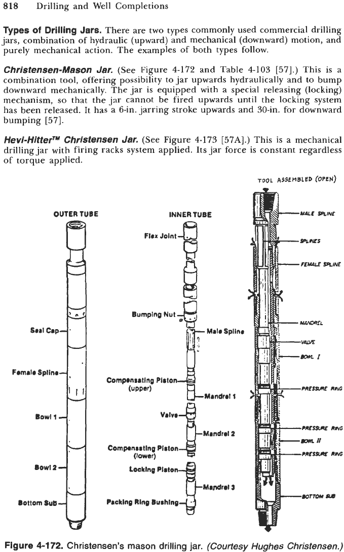
Christensen-Mason
Jar.
(See Figure
4-172
and Table
4-103 [57].)
This
is
a
combination tool, offering possibility to jar upwards hydraulically and to bump
downward mechanically. The jar is equipped with a special releasing (locking)
mechanism,
so
that the jar cannot be fired upwards until the locking system
has been released. It has a 6-in. jarring stroke upwards and 30-in. for downward
bumping
[57].
Hevi-HitterrM Christensen
Jar.
(See Figure
4-173 [57A].)
This is a mechanical
drilling jar with firing racks system applied. Its jar force is constant regardless
of
torque applied.
TOOL
ASSEMBLED
(OPEN)
OUTER TUBE
INNER
TUBE
Flex
Joint
fl
El
J!y-iin.
i
Bumping Nut
;&
Compensating Piolon
(upver)
Mrndrrl
1
Mandrrl2
VdVO
Comprnsrting Plslon
(lower)
Locking Platon
~Mardrri
5
Packing
Ring
Buihing
Figure
4-172.
Christensen’s mason drilling jar.
(Courtesy Hughes Christensen.)
Drilling Bits and Downhole
Tools
819
I
II
Table 4-103
Christensen’s Mason Drilling Jar
I
I
I
I
1
Courtesy Hughes Christensen.
II.
.O
0
II
I
.....
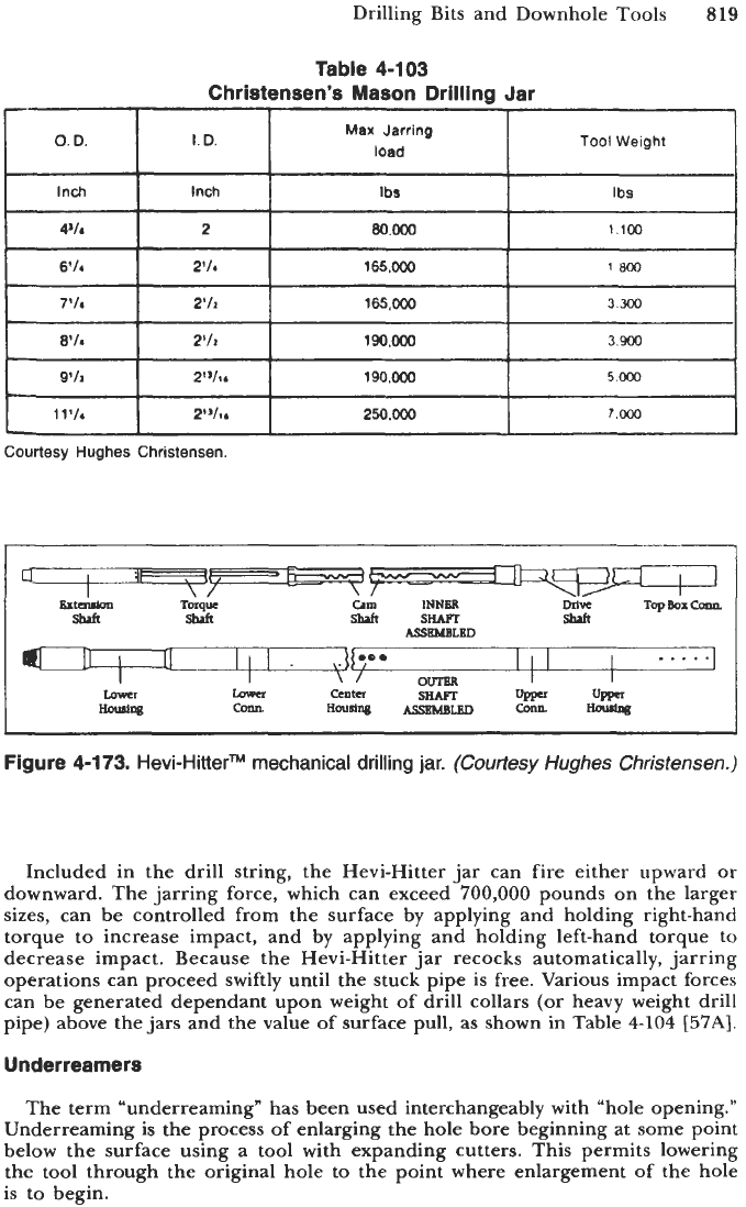
Included in the drill string, the Hevi-Hitter jar can fire either upward or
downward. The jarring force, which can exceed
700,000
pounds on the larger
sizes, can be controlled from the surface by applying and holding right-hand
torque to increase impact, and by applying and holding left-hand torque to
decrease impact. Because the Hevi-Hitter jar recocks automatically, jarring
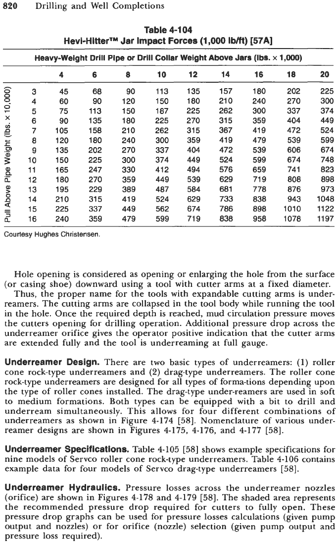
operations can proceed swiftly until the stuck pipe is free. Various impact forces
can be generated dependant upon weight of drill collars (or heavy weight drill
pipe) above the jars and the value
of
surface pull, as shown in Table
4-104
[57A].
Underreamers
The term “underreaming” has been used interchangeably with “hole opening.”
Underreaming is the process of enlarging the hole bore beginning at some point
below the surface using a tool with expanding cutters. This permits lowering
the tool through the original hole to the point where enlargement of the hole
is to begin.
820
Drilling and Well Completions
Table 4-1 04
Hevi-HitterTM Jar Impact Forces (1,000
Ibm)
[57A]
-~
Heavy-Welght
Drill Pipe or Drlll
Collar
Weight
Above
Jars
(Ibs.
x
1,000)
4 6
8
10
12
14 16 18
20
45
9
4 60
6 90
cri
p
7 105
E
8 120
.P
9 135
10 150
11 165
h
12 180
$
13 195
14 210
=
15 225
a'
16 240
h
83
E5 75
v
2
68
90
113
135
158
180
202
225
247
270
229
31 5
337
359
90
120
150
180
210
240
270
300
330
359
389
41 9
449
479
113
150
187
225
262
300
337
374
41 2
449
487
524
562
599
135
180
225
270
31 5
359
404
449
494
539
584
629
674
71 9
157
21
0
262
31 5
367
41 9
472
524
576
629
681
733
786
838
180
240
300
359
419
479
539
599
659
71 9
778
838
898
958
202
270
337
404
472
539
606
674
74 1
808
876
943
1010
1078
225
300
374
449
524
599
674
748
823
898
973
1048
1122
1197
Courtesy
Hughes Christensen.
Hole opening is considered as opening or enlarging the hole from the surface
(or
casing shoe) downward using a tool with cutter arms at a fixed diameter.
Thus, the proper name for the tools with expandable cutting arms is under-
reamers. The cutting arms are collapsed in the tool body while running the tool
in the hole. Once the required depth is reached, mud circulation pressure moves
the cutters opening for drilling operation. Additional pressure drop across the
underreamer orifice gives the operator positive indication that the cutter arms
are extended fully and the tool is underreaming at full gauge.
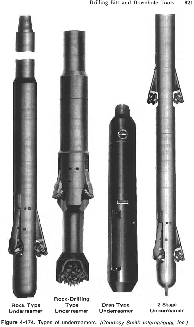
Underreamer Design.
There are two basic types of underreamers:
(1)
roller
cone rock-type underreamers and
(2)
drag-type underreamers. The roller cone
rock-type underreamers are designed for all types of forma-tions depending upon
the type of roller cones installed. The drag-type under-reamers are used in soft
to medium formations. Both types can be equipped with a bit to drill and
underream simultaneously. This allows for four different combinations of
underreamers as shown in Figure
4-174 [58].
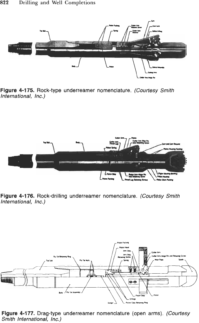
Nomenclature of various under-
reamer designs are shown in Figures
4-175, 4-176,
and
4-177 [58].
Underreamer Specifications.
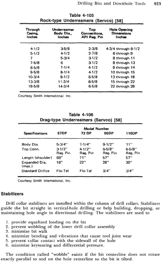
Table
4-105
[58]
shows example specifications for
nine models of Servco roller cone rock-type underreamers. Table
4-106
contains
example data for four models of Servco drag-type underreamers
[58].
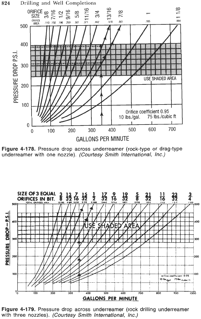
Underreamer Hydraulics.
Pressure losses across the underreamer nozzles
(orifice) are shown in Figures
4-178
and
4-179
[58].
The shaded area represents
the recommended pressure drop required for cutters to fully open. These
pressure drop graphs can be used for pressure losses calculations (given pump
output and nozzles) or for orifice (nozzle) selection (given pump output and
pressure loss required).
Rock
Typre
Underreamer
Drilling
Bits
and Downhole Tools
821
Rock-Drtiftng
Type
Underreamer Underreamer
Figure 4-1
74.
Types
of
underrearners.
(Courtesy
Smith
International,
Inc.)
822
Drilling and Well Completions
Figure 4-1 75.
Rock-type underreamer nomenclature.
(Courtesy
Smith
International, Inc.)
Figure 4-1
76.
Rock-drilling underreamer nomenclature.
(Courtesy
Smith
International, Inc.)
Figure 4-177.
Drag-type underreamer nomenclature (open arms).
(Courtesy
Smith International, Inc.)
Drilling Bits and Downhole Tools
823
Table 4-105
Rock-type Underreamers (Servco)
[58]
Through
Casing.
Inches
Underreamer
Eody
Dia,
Inches
4112
5112
7
7-518
8-518
9518
l(1314
133/8
18-518
3518
4112
5w4
6
7-114
8-114
9-112
1
1-314
14-314
TOP.
Conrmtlons,
API
Reg.
Pin
2-3/8
3112
3112
4112
4112
6518
8518
8518
2-718
4314 through
6112
6
through
9
8
through
11
8
through 13
9
through
14
10
through
15
13through
18
15
through
22
22
through
28
Courtesy Smith International, Inc
Table 4-106
Drag-type Underreamers (Servco)
[581
Model
Number
Specifications
57DP
72
DP
95DP
110DP
Body Dia.
544,
7-114.
9-112"
11"
Top
Conn.
3112"
4112"
6518"
6518"
Length (shoulder)
66''
71"
57'
57"
Expanded Dia.
16"
22" 28'
30"
(max.)
Standard Orifice Flo-Tel
Flo-Tel
314"
314'
Reg.
Pin
Reg.
Pin
Reg.
Pin
Reg.
Pin
Courtesy Smith International, Inc.
Stabilizers
Drill collar stabilizers are installed within the column of drill collars. Stabilizers
guide the bit straight in vertical-hole drilling or help building, dropping, or
maintaining hole angle in directional drilling. The stabilizers are used to
1.
provide equalized loading on the bit
2.
prevent wobbling of the lower drill collar assembly
3.
minimize bit walk
4.
minimize bending and vibrations that cause tool joint wear
5.
prevent collar contact with the sidewall
of
the hole
6.
minimize keyseating and differential pressure.
The condition called "wobble" exists if the bit centerline does not rotate
exactly parallel to and on the hole centerline
so
the bit is tilted.
824
Drilling and Well Completions
Figure 4-1 78.
Pressure drop across underreamer (rock-type or drag-type
underreamer with one nozzle).
(Courtesy Smith International, Inc.)
Figure 4-179.
Pressure drop across underreamer (rock drilling underreamer
with three nozzles).
(Courtesy Smith International, Inc.)
