Lyons W.C. (ed.). Standard handbook of petroleum and natural gas engineering.2001- Volume 1
Подождите немного. Документ загружается.

Drilling Bits and Downhole
Tools
805
~
OPEN
FACED
17/8/91
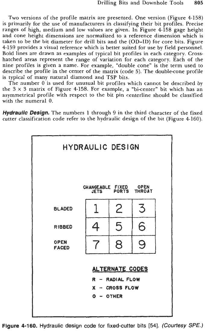
Two versions of the profile matrix are presented. One version (Figure
4-158)
is primarily for the use of manufacturers in classifying their bit profiles. Precise
ranges of high, medium and low values are given. In Figure
4-158
gage height
and cone height dimensions are normalized to a reference dimension which is
taken to be the bit diameter for drill bits and the (OD-ID) for core bits. Figure
4-159
provides a visual reference which is better suited for use by field personnel.
Bold lines are drawn as examples of typical bit profiles in each category.
Cross-
hatched areas represent the range of variation for each category. Each of the
nine profiles is given a name. For example, “double cone” is the term used to
describe the profile in the center of the matrix (code
5).
The double-cone profile
is typical of many natural diamond and TSP bits.
The number
0
is used for unusual bit profiles which cannot be described by
the
3
x
3
matrix of Figure
4-158.
For example, a “bi-center” bit which has an
asymmetrical profile with respect to the bit pin centerline should be classified
with the numeral
0.
Hydrauric
Design.
The numbers
1
through
9
in the third character
of
the fixed
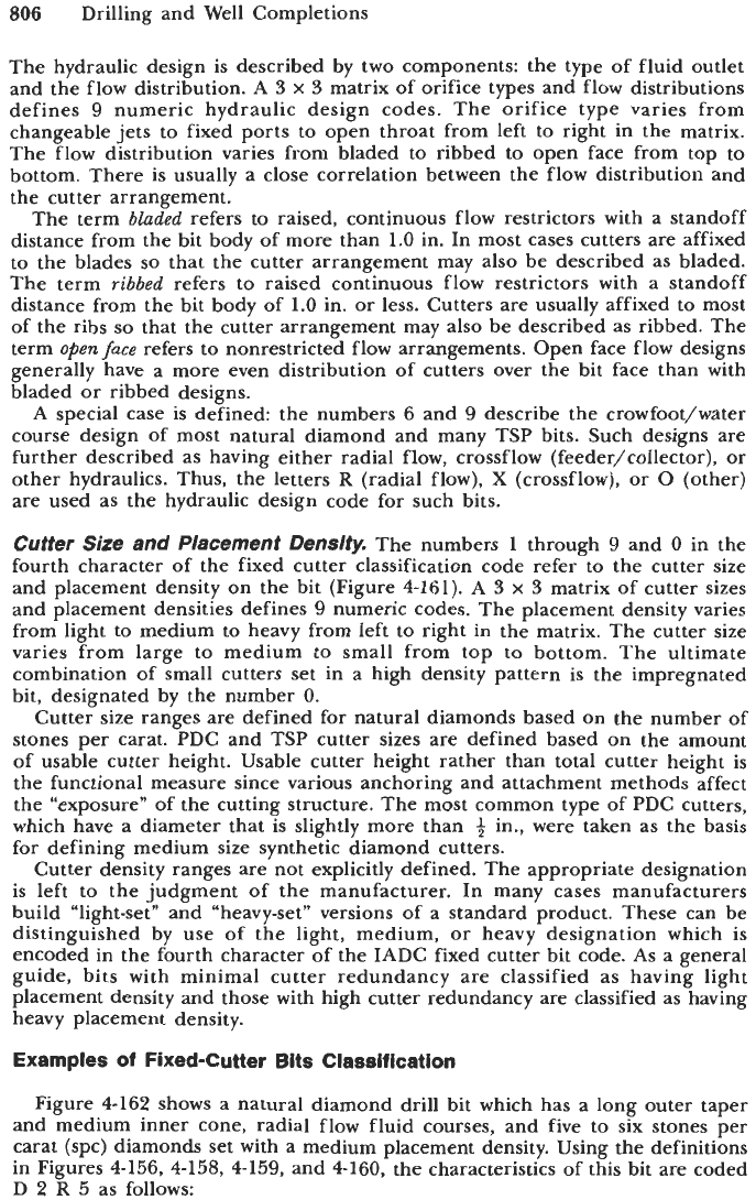
cutter classification code refer to the hydraulic design
of
the bit (Figure
4-160).
HYDRAULIC
DESIGN
CHANGEABLE
FIXED
OPEN
JETS
PORTS
THROAT
ALTERNATE
COOES
R
-
RADIAL
FLOW
X
-
CROSS
FLOW
0
-
OTHER
Figure
4-160.
Hydraulic design code for fixed-cutter
bits
[54].
(Courtesy
SPE.)
806
Drilling and Well Completions
The hydraulic design is described by two components: the type of fluid outlet
and the flow distribution. A
3
x
3
matrix of orifice types and flow distributions
defines
9
numeric hydraulic design codes. The orifice type varies from
changeable jets to fixed ports to open throat from left to right in the matrix.
The flow distribution varies from bladed to ribbed to open face from top to
bottom. There is usually a close correlation between the flow distribution and
the cutter arrangement.
The term
bladed
refers to raised, continuous flow restrictors with a standoff
distance from the bit body of more than
1.0
in. In most cases cutters are affixed
to the blades
so
that the cutter arrangement may also be described as bladed.
The term
ribbed
refers to raised continuous flow restrictors with a standoff
distance from the bit body of
1.0
in. or less. Cutters are usually affixed to most
of the ribs
so
that the cutter arrangement may also be described as ribbed. The
term
open
fuce
refers to nonrestricted flow arrangements. Open face flow designs
generally have a more even distribution of cutters over the bit face than with
bladed or ribbed designs.
A special case is defined the numbers
6
and
9
describe the crowfoot/water
course design of most natural diamond and many
TSP
bits. Such designs are
further described as having either radial flow, crossf low (feeder/collector),
or
other hydraulics. Thus, the letters
R
(radial flow),
X
(crossflow),
or
0
(other)
are used as the hydraulic design code for such bits.
Cutter
Size
and Placement Density.
The numbers
1
through
9
and
0
in the
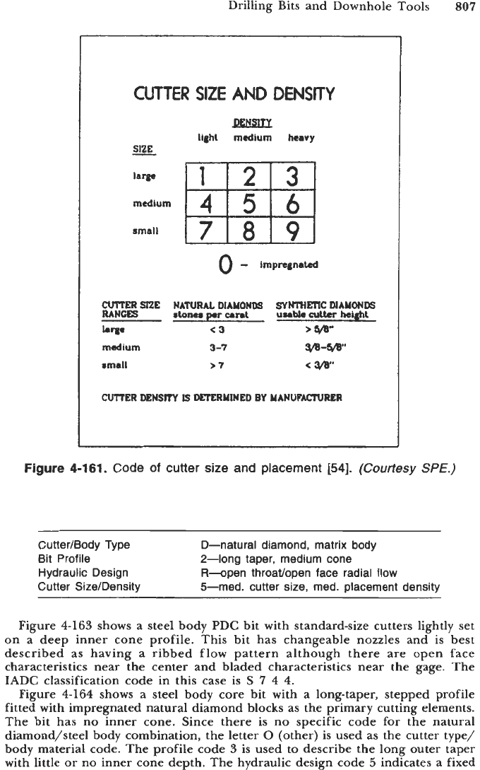
fourth character of the fixed cutter classification code refer to the cutter size
and placement density on the bit (Figure
4-161).
A
3
x
3
matrix of cutter sizes
and placement densities defines
9
numeric codes. The placement density varies
from light to medium to heavy from left to right in the matrix. The cutter size
varies from large to medium to small from top to bottom. The ultimate
combination of small cutters set in a high density pattern is the impregnated
bit, designated by the number
0.
Cutter size ranges are defined for natural diamonds based on the number
of
stones per carat. PDC and
TSP
cutter sizes are defined based on the amount
of usable cutter height. Usable cutter height rather than total cutter height is
the functional measure since various anchoring and attachment methods affect
the “exposure” of the cutting structure. The most common type of PDC cutters,
which have a diameter that is slightly more than
+
in., were taken as the basis
for defining medium size synthetic diamond cutters.
Cutter density ranges are not explicitly defined. The appropriate designation
is left to the judgment of the manufacturer. In many cases manufacturers
build “light-set” and “heavy-set” versions of a standard product. These can be
distinguished by use of the light, medium,
or
heavy designation which is
encoded in the fourth character of the IADC fixed cutter bit code.
As
a
general
guide, bits with minimal cutter redundancy are classified as having light
placement density and those with high cutter redundancy are classified as having
heavy placement density.
Examples
of
Fixed-Cutter
Bits Classification
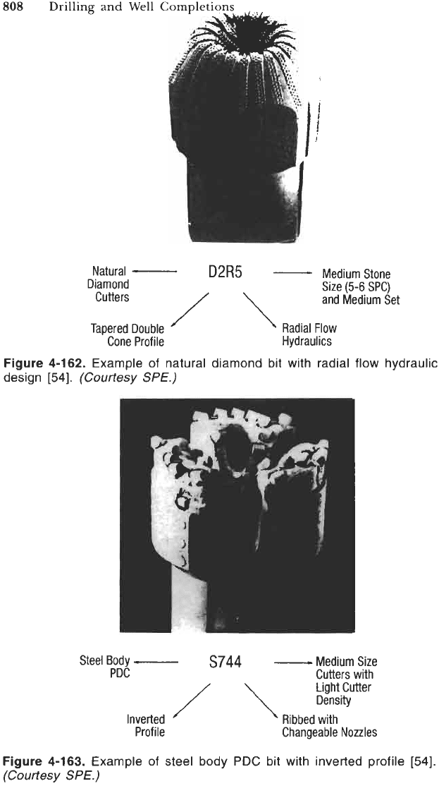
Figure
4-162
shows a natural diamond drill bit which has a long outer taper
and medium inner cone, radial flow fluid courses, and five to six stones per
carat (spc) diamonds set with a medium placement density. Using the definitions
in Figures
4-156, 4-158, 4-159,
and
4-160,
the characteristics of this bit are coded
D
2
R
5
as follows:
Drilling Bits and Downhole
Tools
807
CUTTER
SIZE
AND
DENSITY
RQSLD!
ltghl
medium
heavy
SIZE
-
e3
3-7
>'I
CUTTER
DENSITY
IS
DETERMINED
BY
MANUFACTURER
Figure
4-161.
Code
of
cutter size and placement
[54].
(Courtesy
Sf€.)
Cutter/Body Type
Bit Profile
Hydraulic Design
Cutter Size/Density
D-natural diamond, matrix body
2-long taper, medium cone
R-open throavopen face radial
flow
5-med. cutter size, med. placement density
Figure
4-163
shows a steel body
PDC
bit with standard-size cutters lightly set
on a deep inner cone profile. This bit has changeable nozzles and is best
described as having a ribbed flow pattern although there are open face
characteristics near the center and bladed characteristics near the gage. The
IADC
classification code in this case is
S
7
4
4.
Figure
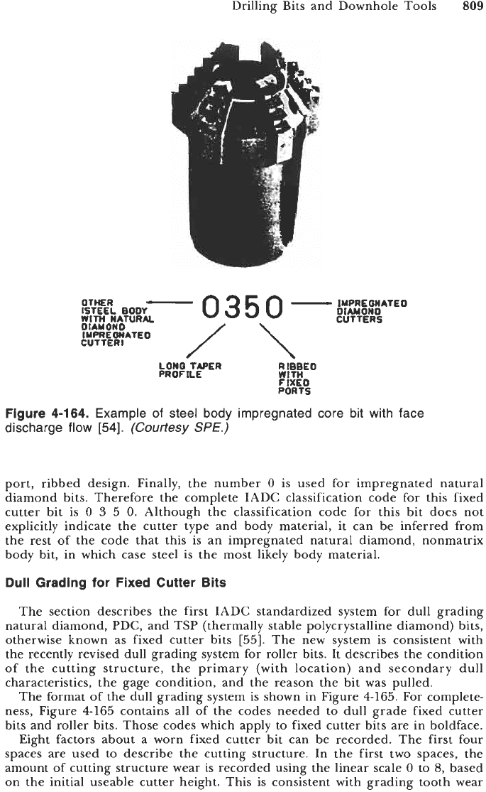
4-164
shows a steel body core bit with a long-taper, stepped profile
fitted with impregnated natural diamond blocks as the primary cutting elements.
The bit has no inner cone. Since there is no specific code for the natural
diamond/steel body combination, the letter
0
(other) is used as the cutter type/
body material code. The profile code
3
is used to describe the long outer taper
with little
or
no inner cone depth. The hydraulic design code
5
indicates
a
fixed
808
Drilling and Well Compl
'
*I.
'
..
I
f
I
D2R5
-
Medium Stone
Natural
-
Diamond
Size
(5-6
SPC)
Cutters
and
Medium
Set
/\
Tapered
Double
'
Cone
Profile
'
Radial
Flow
Hydraulics
Figure
4-162.
Example of natural diamond bit with radial
design
[54].
(Courtesy
SPE.)
flow hydraulic
Steel
Body
-
S744
-
Medium
Size
PDC
Cutters with
Light
Cutter
/
\
Density
Inverted
Ribbed with
Profile Changeable
Nozzles
Figure
4-163.
Example of steel body
PDC
bit with inverted profile
[54].
(Courtesy
SPE.)
Drilling Bits and Downhole Tools
809
WITH
ISTEEL
OTHER
NATURAL
BOW
-0350-~::~
OIAMONO
OIAUONO
IYPRE
ONATE0
CUTTER1
/\
LONQ
TAPER
R
I&EO
PROF
1LE
WITH
FIXE0
PORTS
Figure 4-164.
Example
of
steel body impregnated core bit with face
discharge flow
[54].
(Courtesy
SPE.)
port, ribbed design. Finally, the number
0
is used for impregnated natural
diamond bits. Therefore the complete IADC classification code for this fixed
cutter bit is
0
3
5 0.
Although the classification code for this bit does not
explicitly indicate the cutter type and body material, it can be inferred from
the rest of the code that this is an impregnated natural diamond, nonmatrix
body bit, in which case steel is the most likely body material.
Dull Grading for Fixed Cutter
Bits
The section describes the first IADC standardized system for dull grading
natural diamond, PDC, and TSP (thermally stable polycrystalline diamond) bits,
otherwise known as fixed cutter bits
[55].
The new system is consistent with
the recently revised dull grading system for roller bits. It describes the condition
of the cutting structure, the primary (with location) and secondary dull
characteristics, the gage condition, and the reason the bit was pulled.
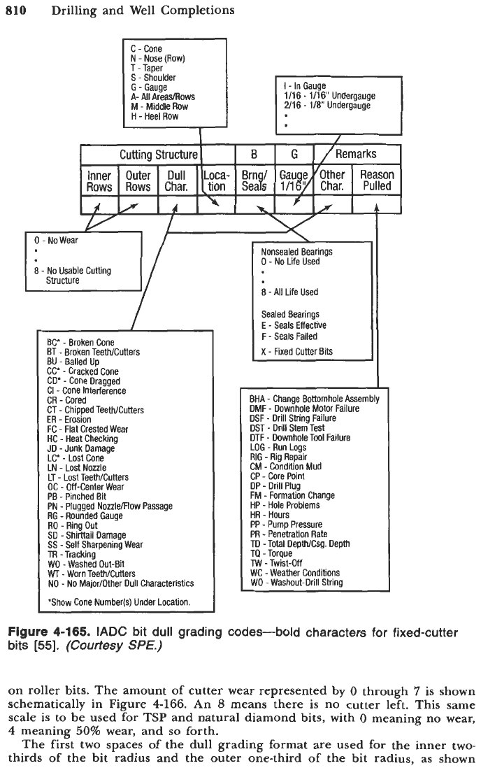
The format of the dull grading system is shown in Figure
4-165.
For complete-
ness, Figure
4-165
contains all of the codes needed to dull grade fixed cutter
bits and roller bits. Those codes which apply to fixed cutter bits are in boldface.
Eight factors about a worn fixed cutter bit can be recorded. The first four
spaces are used to describe the cutting structure. In the first two spaces, the
amount of cutting structure wear is recorded using the linear scale
0
to
8,
based
on the initial useable cutter height. This is consistent with grading tooth wear
810
Drilling and Well Completions
1/16
-
1/16'
Undergauge
2/16
-
1/8
Undergauge
8
-
No Usable Cutting
('L
y
BC
-
Broken
Cone
BT
-
Broken Teeth/Cutters
BU
-
Balled Up
CC'
-
Cracked Cone
CD"
-
Cone Dragged
CI
-
Cone Interference
CR
-
Cored
CT
-
Chipped Teeth/Cutters
ER
-
Erosion
FC
-
Flat Crested Wear
HC
-
Heat Checking
.ID
-Junk Damage
LC'
-
Lost Cone
LN
-
Lost Nozzle
LT
-
Lost Teeth/Cutters
OC
-
Off-Center Wear
PB
-
Pinched Bit
PN
-
Plugged Nozzle/Flow Passage
RG
-Rounded Gauae
RO
-
Ring
Out
SO
-Shirttail Damage
SS
-
Self
Sharpening
Wear
TR -Tracking
WD -Washed
Out-Bi
WT
-
Worn Teeth/Cutters
NO
-
No
MajodOther
Dull
Characteristics
'Show Cone Number@) Under Location.
Nonsealed Bearings
0
-
No Life Used
8
-All Life Used
sealed
Bearings
E
-
Seals
Effective
F
-
Seals Failed
X
-
Fixed Cutter Bits
BHA
-
Change Bottomhole Assembly
DMF
-
Downhole Motor Failure
DSF
-
Drill
String
Failure
DST
-
Drill Stem Test
DTF
-
Downhole Tool
Failure
LOG
-
Run
Logs
RIG
-
Rig Repair
CM
-
Condition Mud
CP
-
Core Point
DP
-
Drill Plug
FM
-
Formation Change
HP
-
Hole Problems
HR
-
Hours
PP
-
Pump Pressure
PR
-
Penetration Rate
TO -Total DepthiCsg.
Depth
TO
-Torque
TW
-
Twist-Off
WC -Weather Conditions
WO
-
Washout-Drill String
Figure 4-165.
IADC
bit dull grading codes-bold characters for fixed-cutter
bits
[55].
(Courtesy
SPE.)
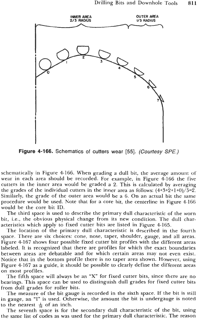
on roller bits. The amount
of
cutter wear represented
by
0
through
7
is shown
schematically in Figure
4-166.
An
8
means there is no cutter left. This same
scale is to be used for TSP and natural diamond bits, with
0
meaning no wear,
4
meaning
50%
wear, and
so
forth.
The first two spaces of the dull grading format
are
used for the inner two-
thirds of the bit radius and the outer one-third
of
the bit radius, as shown
Drilling Bits and Downhole Tools
811
INNER
AREA
OUTER
AREA
213
RADIUS
1/3
RADIUS
Figure
4-166.
Schematics
of
cutters wear
[55].
(Courtesy
SPE.)
schematically in Figure
4-166.
When grading a dull bit, the average amount of
wear in each area should be recorded. For example, in Figure
4-166
the five
cutters in the inner area would be graded a
2.
This is calculated by averaging
the grades of the individual cutters in the inner area as follows:
(4+3+2+1+0)/5=2.
Similarly, the grade of the outer area would be a
6.
On an actual bit the same
procedure would be used. Note that for a core bit, the centerline in Figure
4-166
would be the core bit ID.
The third space is used to describe the primary dull characteristic of the worn
bit, i.e., the obvious physical change from its new condition. The dull char-
acteristics which apply to fixed cutter bits are listed in Figure
4-165.
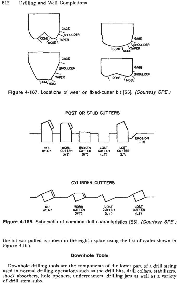
The location of the primary dull characteristic is described in the fourth
space. There are six choices: cone, nose, taper, shoulder, gauge, and all areas.
Figure
4-167
shows four possible fixed cutter bit profiles with the different areas
labeled. It is recognized that there are profiles for which the exact boundaries
between areas are debatable and for which certain areas may not even exist.
Notice that in the bottom profile there is no taper area shown. However, using
Figure
4-167
as a guide, it should be possible to clearly define the different areas
on
most profiles.
The fifth space will always be an
“X”
for fixed cutter bits, since there are
no
bearings. This space can be used to distinguish dull grades for fixed cutter bits
from dull grades for roller bits.
The measure of the bit gauge is recorded in the sixth space. If the bit is still
in gauge, an
“I”
is used. Otherwise, the amount the bit is undergauge is noted
to the nearest
+
of an inch.
The seventh space is for the secondary dull characteristic of the bit, using
the same list of codes as was used for the primary dull characteristic. The reason
812
Drilling and Well Completions
Figure
4-167.
Locations
of
wear
on
fixed-cutter bit
[55].
(Courtesy
SPE.)
POST
OR
STUD
CUTTERS
No
KRN
BROKEN
LOST
LOST
WEAR
CUTTER
CUTTER
CUTTER CUTTER
cwn
(BT) (LT) (LT)
CYLINDER
CUTTERS
m3RN
LOST LOST
(WT) (LT) (LT)
QlTTER
No
WEAR
CUTTER
CUTTER
Figure
4-1
68.
Schematic
of
common dull characteristics
(551.
(Courtesy
SPE.)
the bit was pulled is shown in the eighth space using the list
of
codes shown in
Figure
4-165.
Downhole
Tools
Downhole drilling tools
are
the components
of
the lower part
of
a drill string
used in normal drilling operations such as the drill bits, drill collars, stabilizers,
shock absorbers, hole openers, underreamers, drilling
jars
as
well as a variety
of
drill stem subs.
Drilling Bits and Downhole Tools
813
As
drill bits, drill collars and drill stem subs are discussed elsewhere this
section regards shock absorbers, jars, underreamers, and stabilizers.
Shock Absorbers
Extreme vertical vibration throughout the drill string are caused by hard,
broken or changing formations, and the drilling bit chafing against the bottom
formation as it rotates.
In shallow wells, the drill string transmits the vibration oscillations all the
way to the crown block of the drilling rig. The affect can be devastating as welds
fail, seams split and drill string connections break down under the accelerated
fatigue caused by the vibrations. In deep holes, these vibrations are rarely
noticed due to elasticity and self-dampening effect of the long drill string.
Unfortunately, the danger
of
fatigw still goes on and has resulted in many
fishing operations.
The drill string vibration dampeners are used to absorb and transfer the shock
of drilling to the drill collars where it can be borne without damaging or
destroying other drill string equipment. Their construction and design vary with
each manufacturer. To effectively absorb the vibrations induced by the drill bit,
an element with a soft spring action and good dampening characteristics is
required. There are six basic spring elements used:
(1)
vulcanized elastometer,
(2)
elastomeric element,
(3)
steel wool,
(4)
spring steel,
(5)
Belleville steel springs,
(6)
gas compression.
Types of Shock Absorbers.
There are eight commonly used commercial
shock absorbers.
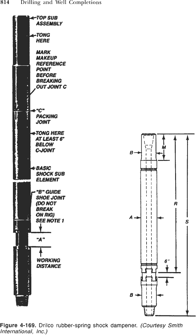
Drilco Rubber vpe.
See Figure
4-169
and Table
4-102 [56].
Shock is absorbed
by an elastometer situated between the inner and outer barrels. This shock
absorbing element is vulcanized to the barrels. The torque has to be transmitted
from the outer into the inner barrel. This tool is able to absorb shocks in axial
or in radial directions. There is no need to absorb shocks in the torque because
the drill string itself acts like a very good shock absorber
so
the critical shocks
are in axial directions. These tools cannot be used at temperatures above
200°F.
Though they produce a small stroke the dampening effect is good
[56].
Christensen Shock-Eze.
See Figure
4-170 [57].
A
double-action vibration and
shock absorber employing Belleville spring elements are immersed in oil.
The tool features a spline assembly that transmits high torque loads to the bit
through its outer tube, while the inner assembly absorbs vibration through a series
of steeldisc springs. The spring system works in both suspension and compression.
The high shock-absorbing capabilities of this tool are attained by compression
of the stack of springs within a stroke of five inches. The alternating action of
the patented spring arrangement provides a wide working range, under all
possible conditions of thrust and mud pressure drop.
Placement
of
Shock Absorber in Drill String.
Many operators have their own
way of placing shock absorbers in the drill string (see Figure
4-171) [57].
In
general, the optimum shock absorbing effect is obtained by running the tool
as near to the bit as possible. With no deviation expected, the tool should be
installed immediately above the bit stabilizer as shown in Figure
4-171C.
In holes with slight deviation problems, the shock absorber could be run on
top of the first or second string stabilizer. For situations where there are severe
814
Drilling and Well Completions
t
L
R
I-
S
Figure 4-1
69.
Drilco rubber-spring
shock
dampener.
(Courtesy Smith
International, Inc.)
