Lyons W.C. (ed.). Standard handbook of petroleum and natural gas engineering.2001- Volume 1
Подождите немного. Документ загружается.

In
In
t-
."
B
a"
v1
c
0
."
Y
.3
8
2
0
u
bb
j;
c
."
&
OZILS
W9tD
WLC
W9tP
009PP
009tP
Wltt
009P)
OOZPP
W6LC
W9P*
OOP6C
0068i
OO6LC
ow**
OW6C
0068i
WZt+
W55f
WPSZ
Wt6S
Wltc
WSSf
WZOf
WIM
OOPS2
WZOL
WlZZ
WSZf
Wl2Z
W261
M)9ot
OMiZ
WPCI
WSI
I
OOtcI
(5)
V!Ol
POL
Wssr
00i99
OLSlS
OLSI5
0999t
0999P
0999t
0999c
0%
55
OSE
55
OSOEP
050fP
osoit
osoit
0568f
0568C
0568f
0568i
08f%
0f92C
Of
9Zf
OD8
I
P
OSSZf
0552c
O55Zi
OtMZ
OSMZ
OW62
OLt62
09991
OffEC
0C65Z
099C2
09tLZ
89661
05191
019tl
019tl
(0
d!d
01591Pl OVZZVL
09P82II WELLS
09P8Z11 OZEZZS
08C5801
OLi22S
OPPIOZI
OZl225
OVOSCZI OLfZZS
09P8Zll OW565
OtSlOZl 000565
008856
08129e
Of09901 08129t
0891111 08L29*
W8856 OOL81*
0825801
Wl81P
0809901
OOL81t
0891111 OOL8lP
OtSIll
OZlC85
O2916L 065011
Of09901 OS9615
OZL816 W566f
085Z16 00566f
021816 09b19E
02916L 09t19f
085216 06815t
OLZ9ZL 058MIP
09PS66
02888t
OZZ9ZL 06108f
WEL99 066LtC
025191
O800Lf
OL9LOP
08OOOf
oszszri
WCLLS
osrs8oi
08mt
089r16 06501~
~89~16 ms6t.r
089~16 09mr
ozs9fs 066r~
oowr
OEEILZ
OL~LOS
owuz
L
1
L
L
L
1
1
L
L
L
L
L
L
1
1
1
L
L
L
1
1
L
1
L
L
1
1
L
L
L
L
Z/I
9
1
9
9
9
01
01
01
01
01
01
01
01
01
01
01
01
01
01
01
01
01
01
L
ZII
L
Z/I
l
2ll
f
E
P/f
z
Zll
z
Zll
f
*/f
t
PIE
E
E
E
PIE
2
t/f
f
f
f
PIE
2
*/E
z
01
911f1
2
01
91/11
2
01
f
01
t/I
f
01
911f12
01
91lLL
01
Pllf
01
911flZ
oi
911112
01
911LZ
Z/I 6 91/1
Z
01
HlZ
211
6 9llL
t
Z/l6 911112
ZII 6 9116Z
82
82
st
e
zmz
8/S
9
8/r9
*/I
9
S/f
9
9
111
9
9
8lf
9
t/r
9
Elf
9
9
9
9
SlE
9
9
9
9
9
211
5
til
s
9
9
211
s
2II
5
9
Zll
5
*/I
5
ZI1
5
5
Zll
5
5
8/S
t
S
*/E
P
8/1
P
UIL
t
811
t
'(r0
SLI'Z
8ll
5
sicr
811
s
SLL'L
91111
b
5LF'f
8ll
5
SLB'Z
91/11P
529Z 91111
P
SLCZ
91111P
5Lf'f
s/r
5
ELCZ
sr/rr
t
SLL'E
8ll
5
SLO'Z 91/11
t
518'2
91/11
t
5292
91/11
*
5LL'f
8/1
5
5LO'Z 91/11
t
519'2
91/11
t
5292 91/11
t
nrr
Zll
t
889Z
911E
t
29SZ 91/f
9
SLO'Z
2IIt
5ZI'f Z/I*
889Z
91/f
t
EICZ 911ft
SLB'Z Zll
t
889Z 9VEt
295'2 911Et
EIf'2
81Li
flu2
8/L
f
szrz
81~r
CIf'Z
8lL
t
E9SZ 8/LE
rirz
OIL(
181'1
911f
i
SL8'1 91/Cf
WZ
9UEf
'R!
'TI!
I~L'I
91hr
=!a
WO
31(*I
.XW
ooo'5f
I
OW'rOI
000'501
000'56
000'56
OW'S6
000'56
OWf
OW'
5f
1
OW'LI
000*501
000'50'
WO'501
000'50I
000'56
W0.56
000'56
000'56 9Z8'i
OW'PfI
OW'S6
OW'S6
OtZ'f
0W'SfI
ooo'sor
Ooo'SOI
OW'501
OW'S6
OW'S6
000'56
OtCf
OW'S01
000'56 Z09Z
OW'5tl
000'50I
OW'S6
W'56
WL'L
oocf5f
I
000'501
OOdM
OWY6
151'2
.?rd
PPI
r@uas
,a?
LY22
92ZE
WZZ
11'22
iCI2
*8'lE
69IZ WO'OZ
01'81
26'81
66LI
61'81
IC81
8f'81
66L1
61'81
61'81
IC81
0991 Z/l
t
SI'S1
OCLT
lYll
IOL'51
11'91
9531
SYSI
5551
95'51
5v51
6251
W'Pl
P
89'91
PFPI
OS51
56tl
8f'Pl
2L'iI
tcti
om
ZIIF
51'11
6011
fro1
t66
Of01
8IlZ
(I)
Ill*
IJhl
*z!S
'IM
7M
'WON
.!Pv
'WON
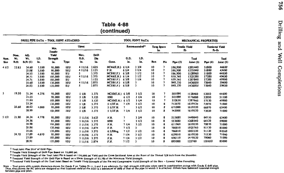
Table
4-88
(continued)
WU
m0
DATA
-
moL
WWNT
AlTACHPD
TOOL
JOINT
DATA
YeMANIcUPRommmi
Nom.
size
4
l/2
5
5
112
21.82
I930
z.60
21.90
24.70
na
25.08
2435
24.71
24
1
1
25.60
24.83
21.34
2135
21.60
23.24
B.62
28.99
14.14
24.98
25.86
25.66
27.89
27.89
28.91
n.x
ID.
in.
1.500
3.5M)
3.500
3.500
33w
3300
3.500
4.276
4M)o
4.7711
4.670
Y*ld
*-@
in.
Tm
95.000
ELI
95.000
IEU
95.000
EU
IMWO
IEU
~~
lO5:000
EU
IUD0
IEU
135.000
EO
95000
IEU
95.000
IEV
105.000
IEU
135.000
IEU
95.000
IEU
lO5.000
IEU
95,WO
IEU
95.000
IEU
lOS.000
IEU
135.000
IEU
135.000
IEU
95.000
IEU
lOS.000
IEU
135,000
IEU
4 11/16
2.625
4
11/16 2.125
5
3.375
4
11/16 2.375
5
3.125
4
11/16
2.875
I
2.875
5
I#
3.37s
51fl
3.125
5
118
3.115
5
118
3.375
5
I@
3.375
5 1/8
3.375
5
11/16 3.62)
5
11/16 3.375
5
11/16 3.375
5
11/16 2.874
5
11/16
3.375
5
11/16
3.375
5
11/16
3.375
511116 2.874
0.1).
ID.
CUM.
in.
in.
NC4UE.H.l
6
1/4
23/4
F.H.
6
114
1
114
NCSfflPJ
6318
3
1/2
NC4MP.H.) 6 l/4 2112
NC50lI.F.)
6318
3
I/)
NC5WI.F.)
65/8
3
NCIO(1.F.) 651.9
3
NCSO(EH.)
6
3/8
31/2
H90
6112
31C
NC5WE.H.)
6 1/2
3
1/4
5
1/2F.H. 7 I14
3
I/2
5
112P.H.
7
3
1/2
5
II2F.H.
7
1/4 3112
Fa.
7 3314
HW
7
3
I12
.OX
10
10
10
10
IO
IO
10
10
IO
IO
IO
IO
IO
10
10
IO
IO
IO
IO
IO
IO
Pin
RP.0)
7
5%*900
7
5%,900
7
596.900
7 659.740
7 659,740
7
848.230
7
848.230
7
501090
7
SOIOW
8
7 712070
553830
8
671wO
8
742000
8 8
553680
553680
8
8
611960 786810
8
786810
8
629810
8
696110
8
895000
Tod
Jdoin(3)
IH)1440
I235(YO
11
211960
1325180
I287840
1436050
1436050
I128460
II7WW
1287840
I619520
1619520
1619520
1448640
1268540
1619520
1925760
I802320
1619520
1619520
125760
Tool
*(4)
Jdns
(SI
51m
44600
5Ioo 4200
51800
U6W
57280
49400
57180 49900
73640
59400
73640
59400
52050
41600
SMSO
Ill00
57530 49900
73970 71000
73030 71000
64120 62400
64120
JWM)
70870
71000
911M
85000
91120
82560
71530 71000
'79060 71wO
101650
85000
Morn
62400
P,
3
a
n
3
'd,
1
5.
2
0
Drill
String:
Composition
and
Design
757
CO""
NOW
00
rx
485
EU75
wo
3%
2
2200
3%
x
2200
3%
&
2100
3
&
1600
485
EU75
OH
1800
85
?&
1500
485
EU 75
NC26(I
F)
L$
;%
2300
3%
&
1800 3%.
!4
1500
485
EU 75
SL-HSO
3X
2
2800 3
%
&;
%
1700
2%
1500
2
6.65
E.U.55
NC26
(1.F.)
%
6.65
I.U. 75
P.A.C.
DZ7h
6.65
E.U. 75
NC260 F
)
6.65
E.U.75
SL-HW
%
8.65
w.75
O.H.
311,
2%
6.85
E.U. 75
NC31 (1.F.) 4%
6.85
E.U.75
W.O.
4%
685
E.U.75
O.H.
@3%
6.85
E.U.75
SL-HW 3%
10.40
E.U.55
NC31 (1.F.I 4%
10.40
I.U.55
E.H.
4X
10.40
I.
U.
55
NC26
(@S.H.)
a33x
10.40
E.U.55
O.H.
3%
10.40
E.U.75
NC31
(If.)
4X
10.40
I.U.75
E.H.
4%
10.40
I.U. 75
NC26
F.H.)
QJ3%
10.40
E.U.75
SL-H9O
3%
10.40
E.U.75
P.AC 03%
10.40
EU.75
O.H.
D3%
10.40
E.U.95
NC31
(I.F.) 4?
10.40
E.U.95
SL-HW
cD3h
10.40
E.U
105
NC31 (IF) LB4x
1040
E.U.
135
NC31 (IF.)
CMx
3%
9.50 E.U.75
NC38(W.O.)
Q4%
9.50
E.U.75
NC38 (I.F.) 4%
9.50 E.U.75
O.H.
a43/,
9.50 E.U.75
SL-HgO
4%
1330
E.U.95
NC38(IF.)
5
2x
11500
13.30
E.U.95 SL-i-490
027;
9700
13.30
E.U.95
H90
2%
12m
13.30
E.U.
105 NC38 (IF.)
5
a)2%
11500
13.30
EU.
135 NC4014F.H.)
5%
13.30
E.U.
135 NC38(3'/2
I.F.)
5
D%
:%
15.50
E.U.75
NC38(I F.)
5
2%
11000
15.50
E.U
95
NC38
(I
F.)
5
We
11500
15.50
E.U.
105 NCa(4F.H.)
5%
2%
15oOo
4):
!?&
11500 4%
x
9700
4:;
!?&
8100
758
Drilling
and
Well Completions
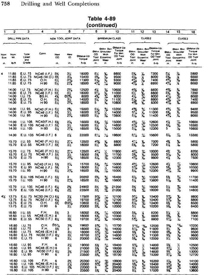
Table
4-89
(continued)
12
3
4 5 6 7 69 10 1112 13 1415 18
4 11.85
11.85
11.85
11.85
14.00
14.00
14.00
14.00
14.00
14.00
14.00
14.00
14.00
14.00
14.00
14.00
15.70
15.70
15.70
15.70
15.70
15.70
15.70
15.70
15.70
15.70
15.70
15.70
4% 13.75
13.75
13.75
13.75
16.60
16.60
16.60
16.60
16.60
16.60
16.60
16.60
16.60
16.60
16.60
16.60
16.60
16.60
16.60
16.60
E.U.75 NCM(1.F.)
W
E.U. 75 NC46
(W.O.)
5$
E.U.75 O.H.
E.U.75 H90
5%
I.U. 75 NC40 (F.H.) 5%
E.U. 75 NC46 (I.F.)
5%
I.U. 75
E.U.75
%%?
E.U.75 H90
5%
I.U. 95 NC40 (F.H.) 5%
E.U.95 NC46 (I.F.) 5%
1.U
95
HBO
5%
I.U. 105 NW(F.H.)
5%
E.U. 105 NC46 (1.F.)
5%
I.U. 105 H90
5%
E.U. 135
NC46
(I.F,) 6
I.U. 55 NC40 (F.H.) 5Y
E.U. 55 NC46 (1.F.)
d
I.U. 75 NC40 (F
H.)
5Y
E.U. 75 NC46 (I.F,)
52
E.U.75 HBO
5%
I.U.
95
NC40 (F.H.)
5%
E.U.
95
NC46 (1.F.)
5%
I.U.95 H90
5%
E.U. 105 NC46 (1.F.)
5X
I.U. 105 HBO
5%
I.U. 135 NC46 (I.F.) 6%
E.U. 135 NC46 (I.F.) 6%
E.U. 75 NC50
(W.O.)
6%
E.U.
75 NC50 (I.F.) 6%
E.U.75 O.H.
5%
E.U.75
HBO
6
I
U.55 F.H.
5%
I.U.
55
NC48 (E.H.) 6
E.U.
55
NC50 (1.F.) 6%
I.U.75 O.H.
05%
I.U.75 F.H.
5%
I.U. 75 NC46 (E.H.) 6
E.U. 75 NC50 (I.F.) 6%
E.U.75 H90 6
I.U.95 F.H. 6
I.U. 95 NC46 (E.H.)
8
E.U. 95 NC50 (I.F.) 6%
I.U.95 H90 6
I.U.105 F.H. 6
I.U. 105 NC46 (E.H.) 6
E.U. 105 NC50 (I.F.) 6%
I.U. 105
H80
6
18ooo
15400
11300
18500
12500
18ooo
8ooo
14ooo
18500
lso00
18ooo
18500
16OOO
leo00
18500
22000
13500
18ooo
13500
18ooo
18500
15700
leo00
16500
2MM)
18500
24900
23500
17500
19700
lo800
2woo
lW
1BMx)
19700
19800
leo00
leo00
19700
2woo
leo00
21000
21500
23500
20300
22OOO
22ooo
23500
5800
6500
8600
6OOO
7600
7200
8wo
7400
6900
9400
gsoo
goo0
lO6W
lo300
lo800
13300
5800
5800
8200
8ooo
7500
logoo
lo300
8800
11700
11400
14800
14800
8800
8800
8500
8400
6800
7300
7100
10200
8600
gsoo
gsoo
lo200
12500
12500
13ooo
12700
14100
lloo
13900
1380Ll
Drill
String:
Composition
and
Design
759
4% 16.60 I.U.135 NC46(E.H.)
6Y
16.60 E.U.135 NCM(1.F.)
6i
25.60
I.E.U.105 5XFH 7%
3%
37000
6%
X
33700
6Y:.
?&
27500
6%
L
23100
5%
21.90
I.U.75
F.H.
7
4
28800
X,
24200
6%
X
18800
6%
X
1660
21.90 l.E.U.95 F.H. 7
3%
32300
6%
?&
296W
30000 67:
6x,
"'
g
24200
24300
ri
'9'
g
20900
20800
21.90 l.E.U
95
HW
7
3%
303MI
6%
21.90 I.E.U.1W F.H. 7% 3% 37000
X
33200
6!!&
X
27500
6%
?&
23100
21.90
I.E.U.135
F.H.
7%
3 44100 7%
?&
42300
6%
?'$
34300
6%
X
29800
24.70
I.U.75
F.H. 7 4
28800
6?&
X
26400
%
22Mx)
6?&
%
17700
24.70 i.E.U.95
F.H.
7%
3%
37000
6?&
!?&
33200
6%
2%
275W
6%
?&
23100
2470
I.E.U.
105 F.H. 7%
3%
37060
61L
N,
36500 6%
%
29800
6%
%
25300
.'.
_,r
~ ~~~
-,-
.I
.- .-
..
.-
~
.
~~
@Basis
ot
calculations
lor
meommended
tool
joint makwp toque asmmed
the
use
of
a thread compound Conlainmg 40-
6046
by
weight Of
linely
powdered
metallic
Zinc
applied lhmughly to
all
threads and Shoulders. and a tensile
slr~sof62.500~SilorcOlumn7and75.000psiforcolumnsl0.l3.and
16.
@W%
minimum
wall
dnll pip.
0.0.
of
tool
joinls
listed
lor
Premium
Class
drill pipe are
bawd
on
drill pipe hawing uniform
y(larlllQ
a minimum
wal!
thrcknar
olBo9b.
OMinimum
box
Shoulder disregards bevel.
a0.D.
01
1001
joints shown
tor
class
2
dnll pipe
we
baled
on
drill pip hawing
all
the
wear
on
one aide and
a
minimum wall
thtckness
01
65%.
W.0.
of
tool
loints
shown
for
Class
3 drill
pipe
are
bow
on
dnll
pipe having all Me
war
on
one
side
and
a
minimum
wall thickness
01
5%.
@The
uae
of
0
0:s
smaller lhan lhoae listed
on
lhe
fable
may
be
aceaptable
on
Slim Hole Tool Joints due
la
special sewice
rsquiremsnts.
mTml
Joint
with dimensions shown ha8
a
lower
torsional yield Mrength lhan
the
drill pipe
M
which
il
is atlached.
*Tool
joint
wtsrde
diameters
(OD)
specified
are
required
to
retain Iorsional strength
In
lhe tool Joint comparable to Ihe
torsional strength
of
the allshed drill pipe,
The
use
01
tool joints, with oulaide dismat?rr smaller than those listed
may
be
acceplabb
in
special mice requirmls 10 provide sutticlenl clearance
in
Cmmng
programs.
In
Such cases.
the torsional
strength
01
the
joint
may
be
cmderaWy
below
that
01
the
drill pip.
body
to
which
it
la
attached.
Tool
ioinn
with
OuW
dimnn
Im
from
Grde
E
drill pipe
an
deqwta
for
hogh
rtnngth
drill pipa
when
4
in
-be
Ntmn
srrmg
with
GRd.
E
drill
prim.
760
Drilling and Well Completions
/EXTRA
LONG
JOINTS
(A) MORE BEARING
AREA REDUCES
WEAR
(6)
MORE LENGTH
FOR
RECUTTING
CONNECTIONS
1
HARDFACI
NG
ON EIJDS AND
TION (OPTIONAL)
FOR LONGER
LIFE
CENTER SEC-
HEAVY
WALL
TUBE
PROVIDES
MAXIMUM WEIGHT
PER FOOT
CENTER UPSET
OF TUBE
ON CENTER
OF
TUBE
(A)
INTEGRAL PART
(B)
REDUCES WEAR
EXTRA
LONG
JOINTS
(A) MORE BEARING
AREA REDUCES
WEAR
(6)
MORE LENGTH
FOR
RECUTTING
CONNECTIONS
Figure
4-134.
Drilco's Hevi-Wate' drill pipe
[42].
(text
continued
from
page
749)
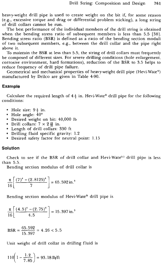
drilling. However, based on field experience, if a heavy-weight drill pipe above
the drill collars is used, it reduces drill pipe failure. The failure of regular drill
pipe and tool joints is influenced by several factors. Probably the most important
one is a cyclic bending stress reversal resulting from the accidental running of
drill pipe in compression, the centrifugal force effect
or
passing through short
and sharp dog-legs,
or
a combination of these factors. In directional drilling, a
Drill String: Composition and Design
761
heavy-weight drill pipe is used to create weight on the bit if, for some reason
(e.g., excessive torque and drag or differential problem sticking), a long string
of drill collars cannot be run.
The best performance
of
the individual members of the drill string is obtained
when the bending stress ratio of subsequent members is less than 5.5
[38].
Bending stress ratio (BSR) is defined as a ratio of the bending section moduli
of two subsequent members, e.g., between the drill collar and the pipe right
above it.
To
maintain the
BSR
at less than 5.5, the string of drill collars must frequently
be composed
of
different sizes. For severe drilling conditions (hole enlargement,
corrosive environment, hard formations), reduction of the
BSR
to 3.5 helps to
reduce frequency of drill pipe failure.
Geometrical and mechanical properties
of
heavy-weight drill pipe (Hevi-Wate@)
manufactured by Drilco are given in Table
4-90.
Example
Calculate the required length
of
44
in. Hevi-Wate" drill pipe for the following
conditions:
Hole size:
94
in.
Hole angle:
40"
Desired weight on bit:
40,000
lb
Drill collars:
7
x
2z
in.
Length of drill collars: 330 ft
Drilling fluid specific gravity:
1.2
Desired safety factor for neutral point: 1.15
Solution
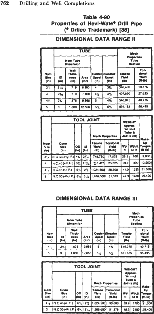
Check to see if the
BSR
of drill collar and Hevi-Wate") drill pipe is less
Bending section modulus of drill collar is
than 5.5.
Bending section modulus
of
Hevi-Wate" drill pipe is
BSR
=
-
65*592
-
-
4.26
e
5.5
15.397
Unit weight
of
drill collar in drilling fluid is
110
1--
=
93.181b/ft
(
;.s25)
762
Drilling
and
Well Completions
Nom
SI28
(In)
5
Table
4-90
Properties
of
Hevi-Wate@ Drill Pipe
(@
Drilco Trademark)
[38]
DIMENSIONAL DATA RANGE
II
Muh
Pmpwiln
Nom Tub.
Tub.
Dhnensbn
&cIlon
TUBE
wall
Tor-
Tblck-
Center
Elentor
Tenslla
slo~l
ID
nns
Awa
Upul UpwI VIeY Yldd
(In)
(In)
(In,)
(In1
(In1
(lb)
(H-IO)
2%
075 9.965
5
4%
546.075 40,715
3
l.W 12.656
5% 5'/8 691.165
56,495
I
TOOL
J
m
NNT
WEIGHT
ma.
WI
InJ
Tuba
L
Jolnls
(IO)
Mako-
UP
TOrqUI
(lt-lb)
9.W
-
13.251
21.m
29.m
DIMENSIONAL DATA RANGE
111
TOOL JOINT
I
WEIGHT
1
I
Ill
Appma.
WI
lncl
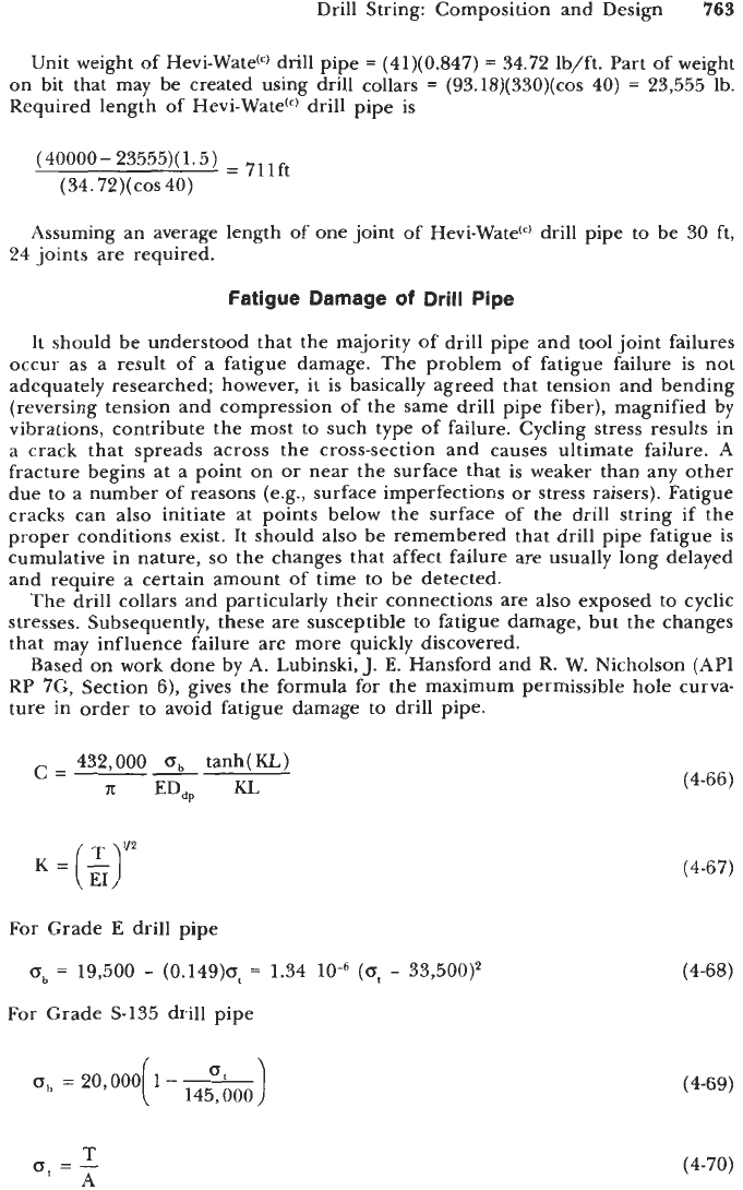
Drill String: Composition and Design
763
Unit weight of Hevi-Wate(') drill pipe
=
(41)(0.847)
=
34.72 Ib/ft. Part of weight
on bit that may be created using drill collars
=
(93.18)(330)(cos
40)
=
23,555 lb.
Required length of Hevi-Wate'') drill pipe is
(40000-
23555)(1.5)
=
,llft
(34.72)(cos40)
Assuming an average length of one joint of Hevi-Wate(c) drill pipe to be 30 ft,
24
joints are required.
Fatigue Damage
of
Drill
Pipe
It should be understood that the majority of drill pipe and tool joint failures
occur as a result of a fatigue damage. The problem of fatigue failure is not
adequately researched; however, it is basically agreed that tension and bending
(reversing tension and compression of the same drill pipe fiber), magnified by
vibrations, contribute the most to such type of failure. Cycling stress results in
a
crack that spreads across the cross-section and causes ultimate failure.
A
fracture begins at a point on or near the surface that is weaker than any other
due to a number of reasons (e.g., surface imperfections
or
stress raisers). Fatigue
cracks can also initiate at points below the surface of the drill string
if
the
proper conditions exist. It should also be remembered that drill pipe fatigue
is
cumulative in nature,
so
the changes that affect failure are usually long delayed
and require a certain amount
of
time to be detected.
The drill collars and particularly their connections are also exposed to cyclic
stresses. Subsequently, these are susceptible to fatigue damage, but the changes
that may influence failure are more quickly discovered.
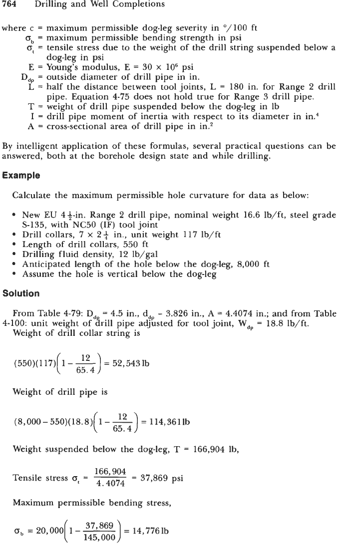
Based on work done by
A.
Lubinski,
J.
E.
Hansford and
R.
W.
Nicholson (API
RP
7G,
Section
6),
gives the formula for the maximum permissible hole curva-
ture
in
order to avoid fatigue damage to drill pipe.
432,000
G,
tanh(
KL)
c=--
=
ED,,
KL
K
=
(6)"
For Grade
E
drill pipe
(T,
=
19,500
-
(0.149)~~
=
1.34
(4
For Grade S-135 drill pipe
Ob
=
20,000
1
-
-
(
14;kOO)
33,500)2
(4-66)
(4-6'7)
(4-68)
(4-69)
(4-70)
T
0,
=
-
A
764
Drilling and Well Completions
where c
=
maximum permissible dog-leg severity in "/lo0 ft
ob
=
maximum permissible bending strength in psi
G~
=
tensile stress due to the weight of the drill string suspended below a
E
=
Young's modulus,
E
=
30
x
lo6
psi
D,,
=
outside diameter of drill pipe in in.
L
=
half the distance between tool joints, L
=
180 in. for Range 2 drill
pipe. Equation 4-75 does not hold true for Range
3
drill pipe.
T
=
weight of drill pipe suspended below the dog-leg in lb
A
=
cross-sectional area of drill pipe in in.*
dog-leg in psi
I
=
drill pipe moment of inertia with respect to its diameter in in.4
By
intelligent application of these formulas, several practical questions can be
answered, both at the borehole design state and while drilling.
Example
Calculate the maximum permissible hole curvature for data as below:
New EU 444.. Range 2 drill pipe, nominal weight 16.6 lb/ft, steel grade
S-135, with NC50
(IF)
tool joint
Drill collars,
7
x
2$ in., unit weight 117 lb/ft
Length of drill collars, 550 ft
Drilling fluid density, 12 lb/gal
Anticipated length of the hole below the dog-leg, 8,000 ft
Assume the hole is vertical below the dog-leg
Solution
From Table 4-79:
Ddp
=
4.5 in., ddp
-
3.826 in.,
A
=
4.4074 in.; and from Table
Weight of drill collar string is
4-100: unit weight of drill pipe adjusted for tool joint, WdP
=
18.8 lb/ft.
(550)( 117) 1
-
-
=
52,543 lb
(
6i24)
Weight of drill pipe is
(8,000-550)(18.8) 1--
=
114,3611b
(
6i24)
Weight suspended below the dog-leg, T
=
166,904 lb,
166,904
4.4074
Tensile stress
tst
=
-
=
37,869 psi
Maximum permissible bending stress,
(2,
=
20,000 1
-
-
=
14,7761b
(
1345
,EO)
