Luo A.C.J. (Ed.) Dynamical Systems: Discontinuity, Stochasticity and Time-Delay
Подождите немного. Документ загружается.

414 N. Unnikrishnan et al.
where
N
Y D
N
Y
0
N
Y
1
N
Y
2
:::
N
Y
q
and
N
Y
0
D D (32.19a)
N
Y
k
D C
N
A
k1
N
B D
h
N
Y
.1/
k
N
Y
.2/
k
i
(32.19b)
To recover the system Markov parameters, one can compute
Y
0
D
N
Y
0
D D (32.20a)
Y
k
D
N
Y
.1/
k
k
X
iD1
N
Y
.2/
i
Y
ki
(32.20b)
To recover the system description in state-space form, one can employ an eigensys-
tem realization method such as the following:
Construct a block Hankel matrix from the system Markov parameters
H
0
D
2
6
6
6
4
Y
1
Y
1
::: Y
1
Y
1
Y
1
::: Y
1
:
:
:
:
:
:
:
:
:
Y
1
Y
1
::: Y
1
3
7
7
7
5
(32.21)
Using the singular value decomposition, the block Hankel matrix H
0
is factorized
as follows:
H
0
D R˙S
T
(32.22)
where R 2<
mm
and S 2<
nn
are two orthogonal matrices and R
T
R D I
m
,
S
T
S D I
n
, ˙ D
s0
00
,ands D diag
1
;
2;
:::
n
.
i
are the sin-
gular values and are in the following order:
1
2
:::
r
>0,where
r D rankfH
0
g. The order of the identified system is determined by examining the
magnitudes of the singular values. The singular values with relatively high mag-
nitudes are associated with the number of states of the system, while the singular
values with relatively low magnitude are assumed to be noise related. A construction
of a minimum order system representation can be established as follows:
O
A D ˙
1= 2
n
R
T
n
H
1
S
n
˙
1= 2
n
(32.23)
O
B D ˙
1= 2
n
S
T
n
E
r
(32.24)
O
C D E
T
m
R
n
˙
1= 2
n
(32.25)
where E
T
r
D
I
r
0
r
::: 0
r
, E
T
m
D
I
m
0
m
::: 0
m
and m are the number of
outputs and r the number of inputs.
To see what the input design does, consider the case for which p D 3, p
2
D 2.
Formulating the new output:
Qy
1
D CAK Qy
1
C CBQu
0
C "
1
D "
1
(32.26)
32 Input Design for Systems Applied to Ultrasonic Transducers 415
Qy
2
D CAK Qy
0
C CBQu
1
C "
2
and using Qu
1
DB
1
AKy
1
and Qy
1
yields
Qy
2
D "
2
(32.27)
Continuing in the same fashion yields:
Qy
3
DCAKCAK"
1
CAKCBu
1
C "
3
(32.28)
Qy
4
DCA
2
KCAK"
1
C CAK"
3
C "
4
CA
2
KCBu
1
C CBu
3
(32.29)
Qy
5
DCA
3
KCAK"
1
C CA
2
K"
3
C CAK"
4
C "
5
CA
3
KCBu
1
C CABu
3
C CBu
4
(32.30)
From the above equations, the output for the second identification experiment is
composed out of a series of residuals " and the open-loop Kalman filter gain Markov
parameter and a series of original inputs times the open-loop system Markov param-
eters [7]. It was shown that the residual has a minor contribution to the output of the
system when compared to the truncated terms of the ARX model; therefore, the out-
put of the system excited by the new input is dominated by the open-loop Markov
parameters.
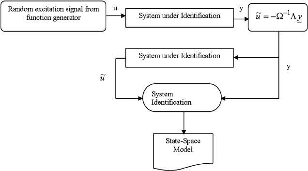
32.4 Input Design for System Identification
The input given in (32.14) is used in subsequent identification experiments as de-
picted in Fig. 32.1. In the first step, the system is excited by a random input and the
input/output data is recorded. From that data set, the corrected input is computed by
Fig. 32.1 Flowchart of proposed IDSI algorithm
416 N. Unnikrishnan et al.
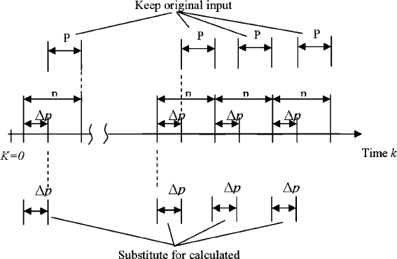
Fig. 32.2 Input signal design with repeated
employing (32.14) and the estimated ARX model parameter matrices. The corrected
input is used for the second identification experiment.
The original input is windowed p data points at a time, and p
2
data points are
substituted by the newly computed values and used for the second identification
experiment as shown in Fig. 32.2. The new ARX model order p
2
is chosen to be
less than p such that the information matrix for the parameter estimation remains of
full rank.
32.5 Experimental Results
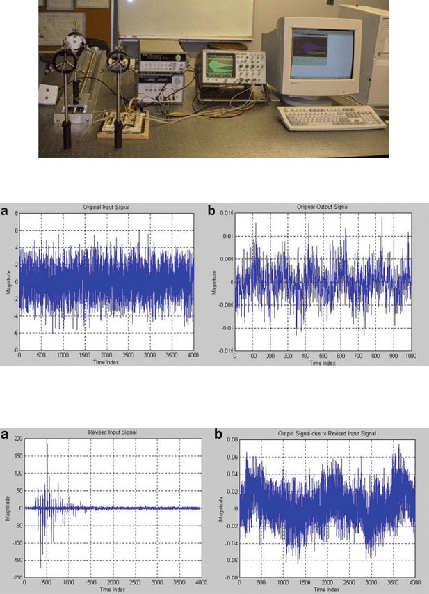
The method proposed in this paper is used for the identification of the mathematical
model of an ultrasonic transmitter–receiver pair shown in Fig. 32.3.
The 3D system uses a single transmitter and multiple receivers fixed in a 3D ref-
erence frame [8]. The ultrasonic transducers being used are 75 KHz transducers and
do not come with a good mathematical model. A good model would greatly help in
the development of a simulation procedure that is being used to select the optimum
electronic components for the signal conditioning circuit being developed. A white
Gaussian, zero-mean, noise signal was fed in to the system (a single transmitter–
receiver pair) and the output recorded as shown in Fig. 32.4a, b.
The output was then used to revise the input, which was then again fed in to the
system, and the revised output was recorded as shown in Fig. 32.5a, b.
32 Input Design for Systems Applied to Ultrasonic Transducers 417
Fig. 32.3 Experimental set-up
Fig. 32.4 Original: (a) input and (b) output signal
Fig. 32.5 Revised: (a) input and (b) output signal
The IDSI algorithm was then used to identify the system model and develop the
state space model [9] as shown below:
x
kC1
D Ax
k
C Bu
k
y
k
D Cx
k
C Du
k
418 N. Unnikrishnan et al.
where
A
14
D
2
6
6
6
6
6
6
6
6
6
4
0:0041635977039 0:98480731601734 0:03653877050420
0:98480731601734 0:00488328785749 0:11368525167570
0:0365387705042 0:1136852516757 0:58870091911101
0:06288097942857 0:01614990771161 0:73027542330511
0:01417428012868 0:01394298451211 0:16010304585432
0:01972613525657 0:03142712127999 0:04006585406940
0:00501883955118 0:00774233608568 0:03179518814198
0:06288097942857
0:01614990771161
0:73027542330511
0:62566436272868
0:10215569036939
0:13144819221398
0:01969274099346
3
7
7
7
7
7
7
7
7
7
5
A
57
D
2
6
6
6
6
6
6
6
6
6
4
0:01417428012868 0:01972613525657 0:00501883955118
0:01394298451211 0:03142712127999 0:00774233608568
0:16010304585433 0:04006585406941 0:03179518814198
0:10215569036939 0:13144819221398 0:01969274099345
0:96043352146054 0:18334817689745 0:04159729651313
0:18334817689745 0:84572873359289 0:43739360310728
0:04159729651314 0:43739360310727 0:89607292609058
3
7
7
7
7
7
7
7
7
7
5
B D
2
6
6
6
6
6
6
6
6
6
4
0:01153858488056
0:00079517351442
0:01506526977112
0:00202684478110
0:00396350806899
0:00639750685067
0:00078894718034
3
7
7
7
7
7
7
7
7
7
5
;CD
2
6
6
6
6
6
6
6
6
6
4
0:01153858488056
0:00079517351442
0:01506526977112
0:00202684478110
0:00396350806899
0:00639750685067
0:00078894718034
3
7
7
7
7
7
7
7
7
7
5
T
;
D D
5:716827158140736e
006
and A D Œa
14
A
57
Note that this is a discrete time state-space model with a sampling time of 2 MHz.
For the identification, the following parameters were selected: number of states
n D 7, p D 75, p
2
D 50.
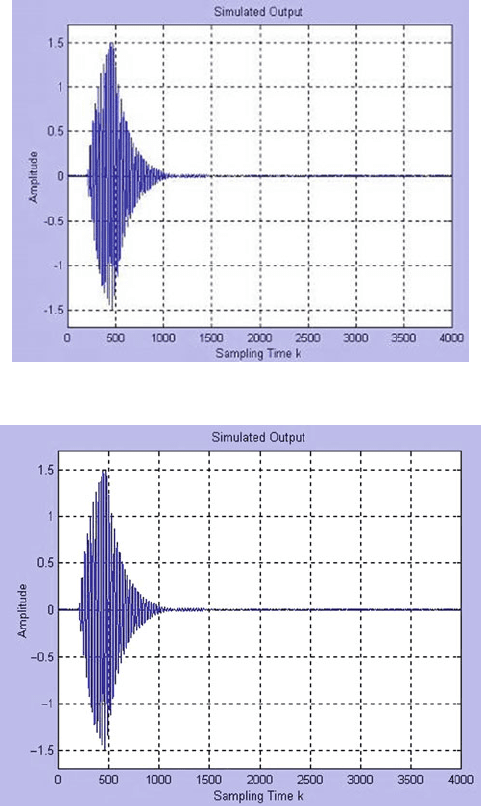
Figure32.6 shows the response of the IDSI identified model of the ultrasonic
transducer pair. Figure32.7 shows the actual response of the system. Note that the
model response is similar in terms of predicting the magnitude response as well
as the time delay in triggering of the signal. It is not very good in predicting the
duration of the signal response.
32 Input Design for Systems Applied to Ultrasonic Transducers 419
Fig. 32.6 Response of the IDSI sensor system model
Fig. 32.7 Actual response of ultrasonic sensor system
32.6 Conclusions and Recommendations
An IDSI method is outlined in this chapter based on input/output data gathered
from random excitation of a system so as to excite all modes. The data set is then
used to compose a new set of more focused input data, from which the system is
excited again and identified. In this chapter, the input design method is used for
the system identification of an ultrasonic sensor pair (transmitter–receiver) so as to
420 N. Unnikrishnan et al.
obtain an accurate model for it. This model is essential for the analysis of a 3D
position estimation system that uses ultrasonic transducers. A single transmitter is
attached to the point of interest, and its position is triangulated based on signals
received at multiple receivers fixed in a 3D environment. An accurate model for the
response of the ultrasonic receivers is essential in the eventual optimization of the
entire system. This chapter only presents results for a single pair (called the system
in this paper), but the results will be applicable for the entire 3D system. Results
are given that show the comparison of the actual output signal of the system and
the output of the model obtained from the IDSI method. This work has applications
in the identification of all complex linear and nonlinear systems. It is particularly
focused toward those systems that can be easily excited by a random noise signal
and the output response can be easily recorded.
References
1. Ljung L (1987) System identification – theory for the user. Prentice-Hall, Englewood Cliffs, NJ
2. Juang J-N (1994) Applied system identification. PRT Prentice-Hall, Englewood Cliffs, NJ
3. Gustavsson I, Ljung L, Soderstrom T (1977) Survey paper: identification of processes in closed-
loop-identifiability and accuracy aspects. Automatica 13:59–75
4. Chen CW, Juang J-N, Huang J-K (1993) Adaptive linear identification and state estimation.
In: Leondes CT (ed) Control and dynamic systems: advances in theory and applications, vol 57,
multidisciplinary engineering systems: design and optimization techniques and their application.
Academic, New York, pp 331–368
5. Huang J-K, Hsiao M-H, Cox DE (1996) Indirect identification of linear stochastic systems with
known feedback dynamics. J Guid Control Dyn 19(4):836–841
6. Huang J-K, Lee HC, Schoen MP, Hsiao M-H (1996) State-space system identification from
closed-loop frequency response data. J Guid Control Dyn 19(6):1378–1380
7. Schoen MP (1997) Input design for system under identification. PhD dissertation, Old Dominion
University
8. Mahajan A, Walworth M (2001) 3D Position sensing using the difference in time-of-flights
to various receivers from a single transmitter of wave energy. IEEE Trans Robot Autom
17(1):91–94
9. Schoen MP, Kuo C-H, Chinvorarat S, Huang J-K (1997) Parameter identifiability for system
under identification using ARX models. In: Proceedings of the 18th ASEM conference, Virginia
Beach, VA, October 23–26, pp 175–181

Chapter 33
Development of a Control System
for Automating of Spiral Concentrators
in Coal Preparation Plants
Josh Hoelscher, Yicheng Pan, Manoj Mohanty, Jarlen Don,
Tsuchin Chu, and Ajay Mahajan
Abstract Spiral concentrators have been widely used in coal preparation plants
in Illinois and elsewhere to clean 1 mm 150 m particle size coal fraction. The
major factors which have made spiral concentrator so popular include its low capi-
tal and operating cost, no chemical reagent or dense medium requirement, and the
ease of operation/maintenance. Spirals are capable of providing excellent clean coal
recovery although at a relatively high ash content. Like any other water-only sepa-
ration process, spirals are also susceptible to continuously fluctuating feed quality
and solids content in the feed slurry, which are quite common in a plant. The main
objective of the project is to develop an inexpensive control system for spiral to auto-
matically adjust the splitter position with fluctuating feed characteristics to maintain
the desired effective separation specific gravity (density cut-point).
33.1 Introduction
This chapter addresses the improvement of product quality and quantity from spiral
circuits, which typically clean 70% of the feed to the fine coal circuit of a preparation
plant. Spiral concentrators are widely used in coal preparation plants in Illinois and
elsewhere because of the ease of their operation, low cost, and the ability to achieve
high clean coal yield. However, the product quality obtained from single stage spiral
cleaning is relatively inferior. In addition, unlike many other density based cleaning
circuits, spiral circuit has no means of being controlled from a plant control room
through a PLC. In fact, spiral circuit is the only link in the chain of a modern day
preparation plant, which has yet to be automated.
Spiral concentrators are used in coal preparation plants to clean 1 mm 150 m
particle size coal fraction, which is too fine to be effectively cleaned by a heavy
T. Chu (
)
Department of Mechanical Engineering and Energy Processes, Southern Illinois
University Carbondale, 1230 Lincoln Drive, Carbondale, IL 62901-6603, USA
e-mail: tchu@siu.edu
A.C.J. Luo (ed.), Dynamical Systems: Discontinuity, Stochasticity and Time-Delay,
DOI 10.1007/978-1-4419-5754-2
33,
c
Springer Science+Business Media, LLC 2010
421
422 J. Hoelscher et al.
medium cyclone and too coarse for froth flotation cells or flotation columns. Spiral
is a flowing film separator, in which the lightest particles move to the outermost
section of the spiral profile, whereas the heaviest particles remain in the inner most
section. There are usually two splitters at the discharge end of a spiral to produce
three product streams, i.e., clean coal product, middlings and tailings, respectively.
The splitter position, which decides the clean coal yield and product quality, is typ-
ically set at one point during initial installation and rarely adjusted again. This
phenomenon results in a significant loss of clean coal to the tailings stream with
fluctuating feed characteristics and solid loading in the feed stream to the spiral.
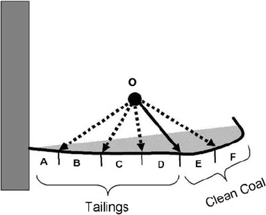
To explain this phenomenon, let us just consider one splitter (for simplicity) in the
following spiral profile schematic (Fig. 33.1). A preliminary test conducted to pre-
pare data indicated a 20% reduction (from 75.9 to 55.9%) in clean coal yield to the
product stream resulting because of a change in the feed solids content from 20 to
10%. A higher product ash content of 12.8% in comparison to 10.6% was caused
because of the above reduction in feed solids content. Understandably, the reduction
in clean coal yield and clean coal ash content was caused by a reduction in specific
gravity of separation (cut-point). It was possible to maintain clean coal yield at the
original level of nearly 76% by a manual adjustment of the splitter position one step
in-ward (from the original location between the sections D and E to a new location
between C and D in Fig. 33.1). Similar adjustments of the splitter position are re-
quired to maintain the same density cut-point to deal with many other fluctuations,
commonly encountered in the mine and plant operating environment, which affect
the feed flow rate, feed washability, distribution of feed flows in the spiral bank, etc.
Past studies [1, 8] indicate that it is essential to maintain the same density cut-point
in each spiral in a spiral-bank to achieve the maximum yield from a spiral circuit.
Common drawbacks of single-stage spiral operation, listed by many investigators
[2, 4, 6], include high density cut-point and misplacement of rock to clean coal.
Two-stage spiral operations were recommended to rectify the above mentioned
draw-backs. Luttrell et al. [5]and[3] examined a variety of circuits for two-stage
spiral operation and concluded that a rougher-cleaner circuit, where the middling
Fig. 33.1 Six sections (A–F)
of the profile of the last turn
of a test spiral; the solid
arrow represents the original
splitter position, whereas
the dotted arrows represent
various possible positions
of the splitter
33 Automating of Spiral Concentrators in Coal Preparation Plants 423
and clean streams are remixed and retreated by a second spiral, produces the lowest
density cut-point and rejects most misplaced rocks. However, the downside to this
two-stage configuration is that it requires substantially more number of secondary
spirals since both clean coal middling products must be rewashed [4]. By comparing
the performance obtained from two-stage middling treatment spiral circuits and the
recently commercialized, PrepTech’s SX7 compound (two stages of spiral cleaning
in a single taller unit) spiral, Bethel and Arnold [2] recommended the use of the
latter over the former both from technical and economic angles.
In light of the above discussion, the main goal of this project was to improve
upon the spiral cleaning performance, so that fine clean coal yield and quality can
be significantly improved in coal preparation plants in Illinois and elsewhere. The
specific objectives include the development of (1) a low cost microprocessor-based
control system for automatic adjustment of the splitter position in each spiral (not
each start) to maintain the desired density cut-points irrespective of the fluctuations
in the plant feed; and (2) a technique to monitor the particle mass (function of both
size and density) across the spiral profile at the discharge end, and then based on this
knowledge adjust the splitter setting to obtain a desired clean coal yield. Three types
of systems were evaluated: mechanical strain gage type, ultrasonic type, and a pres-
sure sensor mat type. The criteria for selecting the right type of control system was
based on several key factors, such as cost, reliability, robustness, ease of retrofitting
to existing spiral banks, and minimal maintenance.
Coal spirals are widely used in preparation plants to clean 1 mm 150 m
particle size coal fraction, which is too fine to be effectively cleaned by a heavy
medium cyclone and too coarse for froth flotation cells or flotation columns. Spiral
cleaning is achieved by two types of flow of the feed coal slurry: primary down-
ward flow and a secondary circular transverse flow on the spiral profile. The latter
creates a decreasing density gradient across the spiral profile (rock has higher den-
sity than coal), whereas the former helps in carrying the density gradient up to the
discharge end, where it is split into three (typically) product streams, namely clean
coal, middling, and tailings stream. Understandably, the density gradient and thus
the gradient of ash content for different particle size fractions will not be the same,
since mass is a function of both particle size and density.
Luttrell et al. [4] explain the misplacement of rock in the clean coal stream due
to the opposite direction of flow pattern in the lower and upper sections of the spiral.
The product splitters are typically so placed that the entire upper section and also the
upper portion of the lower section report to the clean coal launder. Understandably,
the ideal location for the product splitter position is not fixed. It is a function of the
amount of solids on the spiral profile (solid loading), amount of total slurry (vol-
umetric flow) on the profile and also the type of coal (washability characteristics)
being treated at a given point of time. Since all of these three conditions fluctuate in
a plant environment, the ideal location for the splitter position also shifts. A control
system based on the current study will constantly sense the distribution of solid and
liquid on the spiral profile and accordingly an actuator will alter the splitter position
to the ideal location.
