Luo A.C.J. (Ed.) Dynamical Systems: Discontinuity, Stochasticity and Time-Delay
Подождите немного. Документ загружается.

302 E. Keskinen et al.
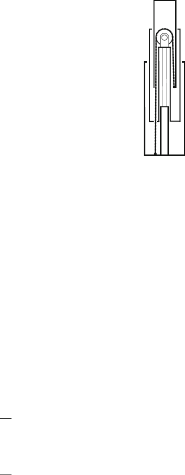
Fig. 25.4 Chain
synchronizing the motion of
links in a multistage telescope
boom
The situation is different if the wire or chain is synchronizing the motion of
individual links in a multiredundant mechanism in Fig. 25.4. In such configurations,
the wire is forming together with the link elements a closed kinematic loop. This
property is useful since it reduces the number of actuators to be controlled during
complicated boom maneuvers.
25.2.2 Elastic Properties of Wire and Chain Elements
In order to model the wire response, a constitutive model of the wire material that
links the strains and strain rates to the tensional stress, is needed
One starts from a very general dependence
D f."; P"/ (25.1)
in which the wire stress is a nonlinear function of strain and strain rate. The effective
elastic modulus for small strains reads then
O
E D
@f
@"
."/ D
O
E./: (25.2)
Correspondingly, the effective viscous modulus takes form
O D
@f
@P"
."/ DO./: (25.3)
The stress rate is then
P D
O
E./P" CO./R": (25.4)
25 Dynamics of Wire-Driven Machine Mechanisms 303
Based on its fiberous structure, wire behaves much more elastically than a steel rod
with the same cross-sectional area [5]. This means that in wire dynamical consider-
ations the actual elastic modulus should be replaced by
O
E D c./E (25.5)
where the reduction factor c usually varies in range 0.35...0.85depending on the
stress level.
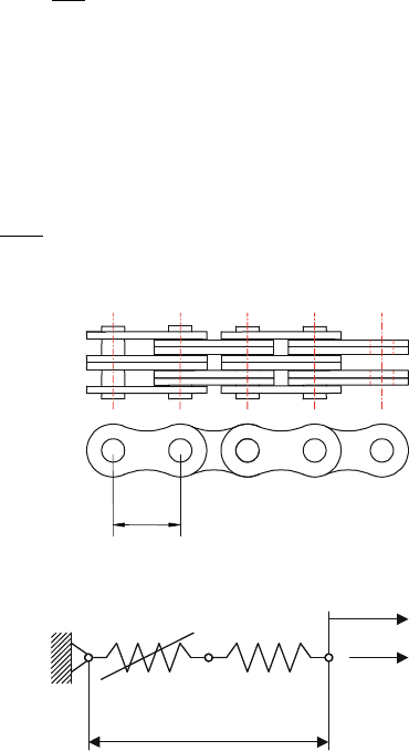
For a chain, the situation in Fig. 25.5 is more complicated since the chain consists
of a finite number of sections having local elasticities in the pin-joints and dis-
tributed elasticity on side plates.
As a model, each chain section will be replaced by an equivalent spring assembly
where the sideplates have a linear elastic behavior with pitch stiffness coefficient
k
1
D
AE
(25.6)
see Fig. 25.6, but the pin-joint has a nonlinear load-displacement relationship of
the form
N D a
b
(25.7)
leading to load-dependent joint stiffness coefficient
k
2
.N / D
@N
@
D a
b
bN
bC1
(25.8)
Fig. 25.5 Chain section
l
Fig. 25.6 Spring models
in series representing one
section of the chain
N
Dl
l
304 E. Keskinen et al.
Chain homogenization is a process where the whole chain is replaced by pitch and
joint spring pairs in series leading to continuous material model with cross-sectional
area A and equivalent elastic constant
O
E D
E
1 C
k
1
k
2
.N /
(25.9)
25.2.3 Kinematics of Wire Motion
Suppose the wire is stretched over guiding wheels located between the winch drum
and work object.
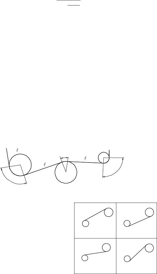
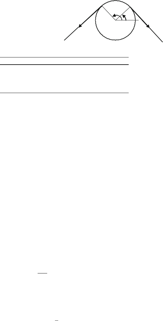
The total wire length L in a multispan arrangement consists of lengths `
i
along
wheel-to-wheel free spans and overlapping lengths s
i
along the contact zones on
wheels in Fig.25.7
L D
X
i
`
i
C
X
i
s
i
: (25.10)
The expression of span and overlapping lengths varies depending on the different
cases shown in Fig. 25.8 and Table 25.1.
If the position vectors of wheel centers and wheel radii are known, the distance
d
i
between wheel centers is in all cases
d
2
i
D .R
iC1
R
i
/.R
iC1
R
i
/ (25.11)
s
i+1
s
i
s
i+2
i
−
1
i
+
1
i
Fig. 25.7 Definition of span and overlapping lengths in wire kinematics
Fig. 25.8 Four basic cases in
wire length computation
A
B
I
A
B
II
A
B
II
I
A
B
IV
25 Dynamics of Wire-Driven Machine Mechanisms 305
Table 25.1 The basic situations of span topology
Case Contact on wheel A Contact on wheel B
I Outside Outside
II Inside Inside
III Outside Inside
IV Inside Outside
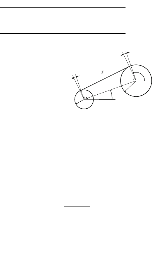
Fig. 25.9 Span length
computation for case I
i
i+1
d
i
i
i+1
R
i+1
R
i
b
i
a
i
f
1
f
2
b
i
i
The span length for cases I and II in Fig.25.9 is
`
i
D
q
d
2
i
R
2
i
(25.12)
where R
i
D R
iC1
R
i
, but for cases III and IV
`
i
D
q
d
2
i
†R
2
i
; (25.13)
where ˙R
i
D R
iC1
C R
i
. The inclination angle ˛ of the center line is in all cases
˛
i
D arctan
Y
iC1
Y
i
X
iC1
X
i
(25.14)
with the replacement ˛<0) ˛ ! ˛ C 2 for avoiding negative angles. The
angular difference between wire span and center line is for cases I and II
ˇ
i
D arctan
R
i
`
i
(25.15)
whereas for cases III and IV
ˇ
i
D arctan
†R
i
`
i
(25.16)
The direction angles of contact points on the wheels can be calculated from case-
dependent formulae below.
306 E. Keskinen et al.
Fig. 25.10 Overlapping
length
e
1
i
e
2
i
i
i
f
1
f
2
Table 25.2 Direction angles of separation points for basic cases
Case Contact on wheel A Contact on wheel B
I
i
2
D ˛ C ˇ C =2
iC1
1
D
i
2
II
i
1
D ˛ ˇ C 3=2
iC1
1
D
i
2
III
i
1
D ˛ ˇ C =2
iC1
1
D
i
2
C
IV
i
2
D ˛ C ˇ C 3=2
iC1
1
D
i
2
The overlapping lengths in Fig. 25.10 s
i
are now easily computed from angular
differences between the angles of in-wheel and out-wheel separation points in
Table 25.2
s
i
D R
i
ˇ
ˇ
'
i
1
'
i
2
ˇ
ˇ
(25.17)
For further need, the unit vectors for span lines for in-wheel and out-wheel direc-
tions are
e
i
1
Dsin '
i
1
i C cos '
i
1
j (25.18a)
e
i
2
D sin '
i
2
i cos '
i
2
j (25.18b)
25.2.4 Tension Dynamics
Because a lifting wire or a chain drive is highly loaded during operation, the
tensional state does not vary so much between the spans. A lumped parameter
model may therefore be accurate enough to model dynamic variation of the average
tensional state N along the whole wire length.
The mass conservation theorem applied to the control volume filled of wire
continuum with instantaneous mass M D V reads
dM
dt
DPV C Q D 0 (25.19)
in which Q is the total flow rate of the wire material flowing out from the control
volume. For a purely axially deforming solid continuum, the density rate is related
to axial strain rate by the expression
P
DP" (25.20)

25 Dynamics of Wire-Driven Machine Mechanisms 307
Combining this with the mass conservation equation then leads to kinematic
equation of the wire continuum
P" D
Q
V
(25.21)
Because tensional force is linked to stress by N D A, the state equation for the
wire tension gets form
P
N D A
O
E.N/Q CO.N /
P
Q
V
(25.22)
By making use of relations
V D AL (25.23)
P
Q D A
P
L (25.24)
for wire volume and flow rate, the state equation finally reads
P
N D A
O
E.N/
P
L CO.N /
R
L
L
: (25.25)
Therateofwirelength
P
L is contributed by the feeding speed v
winch
of winch drum
(the sink), by the speed of work object v
object
and by the stretching effect of moving
guide wheels
P
L D ˝R
winch
C v
winch
e
rope
C v
object
e
rope
X
i
v
i
e
i
1
C e
i
2
: (25.26)
The reaction forces F
j
acting on the wheel bearings moving by velocities v
j
can
be computed from the dynamic wire tension by vector expressions
F
i
D N
i
e
i
1
C e
i
2
: (25.27)
25.3 Boom Mechanics
Hydraulic booms are multibody systems, which can be modeled using either relative
coordinates between the links or using absolute coordinates for link positions. The
latter approach needs also equations of kinematic constraints to couple the motion
of separate links together or, alternatively, contact force equations to describe more
physically the dynamics of joints [6]. In a boom mechanism, the links are connected
to other links, actuators, and wire wheels as illustrated in Fig. 25.11.
If absolute coordinates are used, the differential equation of motion for each link
reads
M Ry C Ky D G C C C H C L; (25.28)

308 E. Keskinen et al.
Fig. 25.11 Link element
connected to hydraulic
actuator, neighboring link,
and wire wheel
S
R
r
j
θ
where the first two elements (S, ) of vector y D
S uv
T
are the rigid body
coordinates of link center of gravity. The remaining components are modal coordi-
nates of the vibratory motion in axial and bending directions.
The position of nodal points fixed to the moving link can be calculated using
kinematic transformation R D R.r; y/ D ŒXY
T
, where the link state variables y
and local link positions r are related to the global Cartesian variables. This makes it
possible to follow also the global positions of wheel centers with link motion. When
the wheels are moving with boom link, their velocity is given for wheel i by
v
i
D J .r
i
/ Py (25.29)
where J D @R=@y is the Jacobian between the Cartesian and state vector spaces
evaluated at the wire wheel node. The right-hand-side terms in (25.28), respectively,
represent gravitational loading, concentrated forces from motion constraints, actua-
tors loading, see (25.37), and the last term is the wire wheel force
L D J.r
i
/
T
F
i
: (25.30)
The wire reaction F
i
can be computed from (25.27) completing the equation system
in wire–boom interaction.
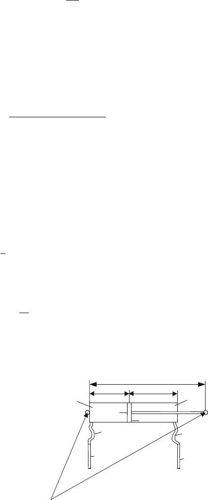
25.4 Fluid Power Circuit
The power source in lifting booms is very often oil hydraulics. Hydraulic volume
element consists of subvolumes in actuator chamber (a), hose (h), and pipe (p). If
lumped parameter approach is used, the dynamic equations for pressure variations
in plus (i DC) and minus (i D) volumes of actuator circuit are
Pp
i
D B
Q
i
V
i
; (25.31)
25 Dynamics of Wire-Driven Machine Mechanisms 309
where the effective volume of fluid V
i
is given by
V
i
D
X
j Da;h;p
1 C
B
ˇ
ij
V
ij
(25.32)
from addition of subvolumes having actual volume V
ij
and equivalent bulk modulus
ˇ
ij
. The actuator volumes are related to link positions by formulae
V
Ca
D A
C
.z z
min
/;
V
a
D A
.z
max
z/; (25.33)
where
z D
p
.R
C
R
/.R
C
R
/ (25.34)
is the instantaneous cylinder length connecting link nodal points to cylinder eyes at
plus and minus ends, see Fig. 25.12.
Contribution to flow into the volume is coming from valve flow q
i
and from the
displacement flow in actuator piston generated by the link movements
Q
i
D q
i
C A
i
Px
i
(25.35)
with actuator chambers length rates Px
C
DPz, Px
DPz and cylinder speed
Pz D
1
z
.
P
R
C
P
R
/.R
C
R
/: (25.36)
Once the dynamic pressures are integrated from (25.24), then the actuator load can
be evaluated by
H D
H
z
J
T
.R
C
R
/; (25.37)
where H D p
C
A
C
p
A
is the resulting hydraulic force. The flows through the
valve ports depend on the pressure differences between the pressures p
C
and p
in
Fig. 25.12 Va ri ab l es of an
hydraulic actuator
V
+a
, p
+
A
+
R
−
R
+
A
−
V
−h
V
+h
V
−p
V
+p
x
−
x
+
z
V
−a
, p
−
310 E. Keskinen et al.
Fig. 25.13 Generation of
ramp functions for open loop
driving mode
Quick
u
u
Normal
Creep
t
Q
C
N
actuator volumes and pressures p
s
and p
t
in the supply and tank lines. For a double
action actuator driven by a 4/3 directional control valve, the flows into plus and
minus volumes are given in pushing direction (positive control input u>0, switching
code ID1)by
q
C
D sgn.p
s
p
C
/cu
p
j
p
s
p
C
j
; (25.38a)
q
Dsgn.p
p
t
/cu
p
j
p
p
t
j
(25.38b)
and in pulling direction (negative control input u <0, switching code I D1)by
q
C
D sgn.p
C
p
t
/cu
p
j
p
C
p
t
j
; (25.39a)
q
Dsgn.p
s
p
/cu
p
j
p
s
p
j
(25.39b)
with c D q
nom
u
1
max
p
1
=
2
nom
obtained by measuring volumetric flow q
nom
for fixed
pressure difference P
nom
and full input voltage u
max
.
The classical way to govern the valve in a servo-loop control is to apply PID-
control
u D K
D
Pe C K
P
e C K
I
Z
t
0
e dt; (25.40)
where e is the error between desired and measured values of controlled positions in
the system.
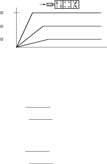
For open loop control, a systematic way is to use ramp functions from an elec-
tronic ramp generator, a family of which is shown on Fig. 25.13.
25.5 System Dynamics Examples
As applications of the presented simplified wire dynamical model, two cases respec-
tively corresponding both kinematically and from control point of view to open and
closed loop structures are considered.
25 Dynamics of Wire-Driven Machine Mechanisms 311
25.5.1 Hydraulic Winch System
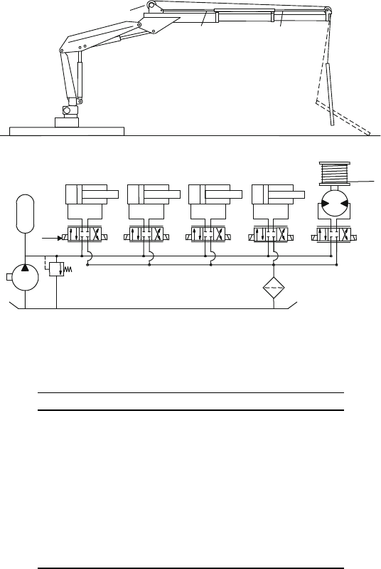
The system is an articulated three link system with rotational joints and hydraulic
actuators at the first two links and a third link that is an expandable boom supporting
a winch moving a chain with a hook at its extremity to carry a load, see Figs. 25.1a
and 25.14.
Based on the component level models presented in previous chapters, a complete
system model has been built up and tested on the following maneuver consisting of
ten ramp inputs to the valves in an open loop control time-sequence.
The above sequence consists of ten actions in four phases corresponding to lift-
ing, boom shortening, tilting, and winching actions in Table 25.3.
CYL1
CYL2
MOT
MOT
CYL3
CYL1 CYL2
CYL3
CYL4
CYL4
DCV1 DCV2 DCV3 DCV4 DCV5
Fig. 25.14 Three link open loop winching system
Table 25.3 Sequence of ramp functions in lifting task of the
hydraulic winch system
Valve Actuator Switch Ramp Time
DCV1 CYL1 1 N0.0
DCV1 CYL1 0 N2.0
DCV2 CYL2 1 N2.0
DCV2 CYL2 0 N3.5
DCV3 CYL3 1 N1.5
DCV3 CYL3 0 N3.0
DCV4 CYL4 1 N1.5
DCV4 CYL4 0 N3.0
DCV5 MOT 1 Q0.0
DCV5 MOT 0 N1.5
