Lopez de Lacalle L.N., Lamikiz A. Machine Tools for High Performance Machining
Подождите немного. Документ загружается.

416 J. Fernández and M. Arizmendi
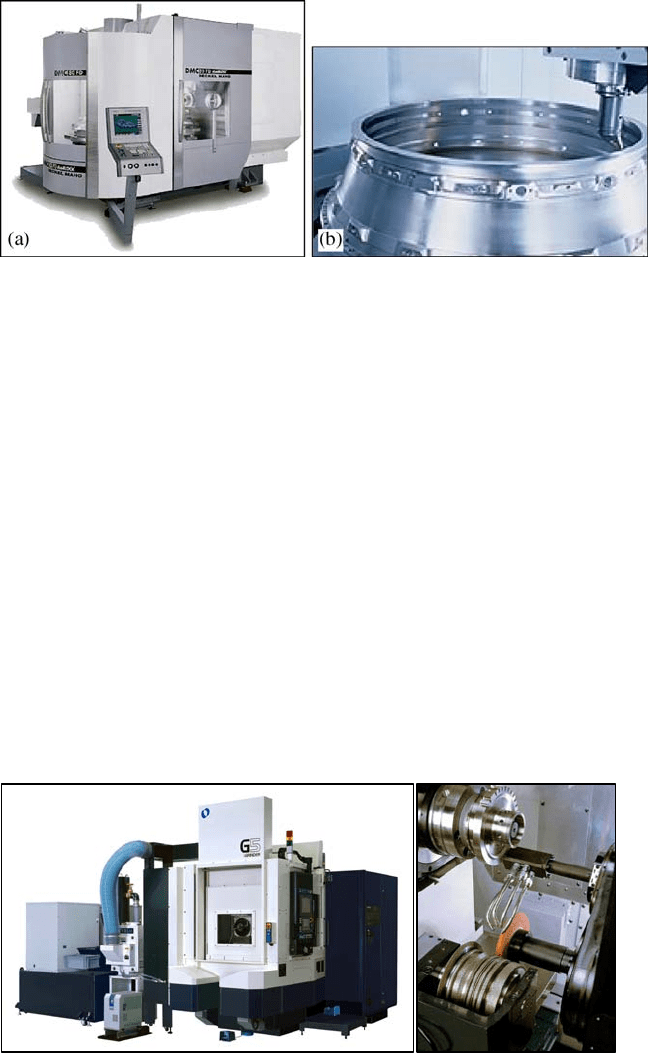
Fig. 12.14 a DMC 80 FD from DMG
®
. b Machining example
Figure 12.14b shows a boring operation on an engine housing performed in this
“turning and milling” machine.
Besides the “turning and milling at the same machine” strategy other machine
strategies are appearing for reducing set-up times. One of them is the “milling and
grinding at the same time” strategy that is being applied to blades, turbine discs
and also to housings. These components have milling and grinding features and
therefore they have to visit both a milling and a grinding machine. This is the clas-
sic approach. But it implies an increasing number of set-ups, fixtures and cost.
Some machine builders trying to reduce the machining cost of these components
have incorporated grinding capabilities in their milling machines creating the so
called “milling and grinding at the same time” strategy. One of them is Makino
®
.
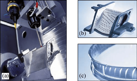
In Fig. 12.15 the “G5 iGrinder” horizontal machining centre is shown. This is
another hybrid 5-axis machining centre suitable for machining special alloys for
aerospace and engine components such as blades, turbine discs and housings.
Reviewing the manufacturing of aerospace engine components it can be con-
cluded that milling is the principal operation followed by turning and grinding.
But there are also other non-traditional processes such as laser, ultrasounds and
Fig. 12.15 Horizontal machining centre G5 iGrinder from Makino
®
12 Machines for the Aeronautical Industry 417
electrodischarge machining (EDM), that have their small and very specific niches
of applications in the manufacturing of engine components. In some cases these
processes are the only way to perform certain operations.
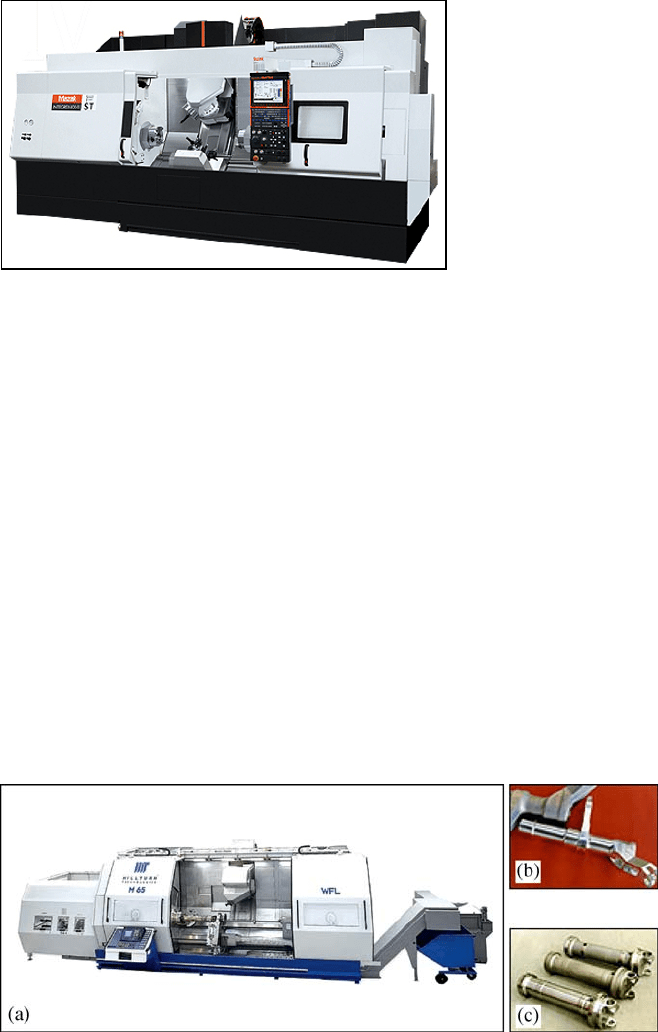
One example of this is the Lasertec 80 Powerdrill from DMG
®
that can drill
holes in difficult-to-cut materials (Fig.12.16) with better tolerances and times than
other more traditional processes.
12.5.3 Machine Tools for Machining Accessories
and Structure Fittings
Accessories and structure fittings are aerospace components, which are smaller
than the aluminium structures. They are never larger than 1000
mm in length.
They are complex in geometry and also require complex fixtures to be fixed to
the machine table. Their tolerances are usually rather demanding, ranging between
0.005 and 0.01
mm, and therefore grinding operations are not unusual. Complex
geometry accessories require a large number of machining operations and to re-
duce cycle times: high-speed tool positioning, small tool changing times and
magazines with a large number of tools are needed.
Because of the expensive fixtures and the demanding precision, it is also very
important to minimise the number of set-ups and hybrid machines are a good solu-
tion because they have been designed to manufacture with fewer and simpler
tools, simple and cheaper fixtures and fewer set-ups. And fewer set-ups means
also more precision.
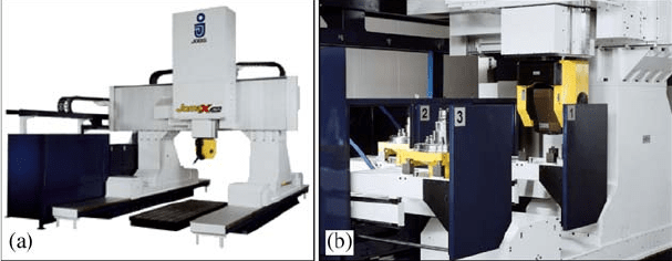
One representative example of these multi-task machines is the new 5 axis
Integrex Mark IV Series machine from Mazak
®
(Fig. 12.17). This type of machine is
a mixture of a turning and milling centre designed to produce components in one
Fig. 12.16 a 5-axis laser precision drilling of holes in engine components with Lasertec 80
Powerdrill from DMG
®
. b Turbine vane made of Inconel. c Compressor ring made of stainless
steel
418 J. Fernández and M. Arizmendi
single set-up. It has a turning spindle (single or dual opposed) and also a milling
spindle head with a linear Y-axis and a rotating B-axis. To shorten cycle times it has
an optional additional tool turret for simultaneous cutting. The machine is very
flexible and, according to the builder, can be competitive with different components
such as: a) round parts with secondary operations, b) fully prismatic parts from
a solid or a casting, c) or sculptured parts such as aerospace components and moulds.
Another example is the Millturn machine from WFL
®
shown in Fig. 12.18a.
This is a turning-milling machine where the tool can be oriented through a B-axis
to machine the workpiece at any angle. Figure 12.18b and c show two fully ma-
chined components from this turning-milling machine.
Typical batch sizes of accessories are less than 100 units/year for between
8 and 20 accessory types. Airbus is an exception with batches of 2,000 per year
since the components are common for many aircraft models. To cope with small
batches with many variants machine tool flexibility is a necessity. About 70% of
those components (mainly valves and pistons) are made of difficult-to-machine
superalloys and the remaining 30% are made of easy-to-machine materials, mainly
Fig. 12.17 Integrex from Mazak
®
Fig. 12.18 a Millturn 65 from WFL
®
and some examples of manufactured parts. b Flap lever.
c Landing gear
12 Machines for the Aeronautical Industry 419
aluminium alloys. For light materials, a very large cutting speed can be used and
a 40,000
rpm spindle would be a good choice, but this same spindle will be too
expensive for machining superalloys since the cutting speed of this material group
is low and a less expensive 6,000
rpm spindle will be sufficient. This problem has
recently been addressed by some builders and they are offering machine tools
equipped with two automatically interchangeable spindles such as the gantry type
machining centre FRF (Q) from the Czech company Tos Kuřim
®
and the JomaX
265, a mobile gantry milling centre for 3/3
+
2/4/5 axis machining from the Italian
company Jobs
®
(Fig. 12.19).
Acknowledgements Our thanks to Fatronik and Invema (Spanish Foundation for Machine Tool
Research) for the information provided, and to all mentioned companies for the pictures.
References
[1] Aerospace and Defence Industries Association of Europe (ASD)
http://www.asd-europe.org/. Accessed 28 March 2008
[2] Aerospace Industries Association. http://www.aia-aerospace.org/. Accessed 28 March 2008
[3] Airbus – Press Release – 7 February 2008
http://www.Airbus.com/en/presscentre/pressreleases/pressreleases_items/08_02_07_Airbus
_forecast_2008.html, Accessed 28 March 2008
[4] Aspinwal DK, Dewes RC, Mantle AL (2005) The Machining of y-TiAl Intermetallic
Alloys. CIRP Ann- Manuf Techn, 54/1:99–104
[5] Ezugwu EO (2005) Key improvements in the machining of difficult-to-cut aerospace super-
alloys. Int J Mach Tools Manuf, 45/12–13:1353–1367
[6] Ezugwu EO, Bonney J, Yamane Y (2003) An overview of the machinability of aeroengine
alloys. J Mater Process Technol 134:233–253
[7] Fatronik (2002) Internal Report: Tendair (Trends in Aircraft Industries)
[8] Invema (2007) Internal Report: Tendencias Tecnológicas y Oportunidades de Negocio
(Business and Technological Opportunities, in Spanish)
[9] Lequeu P, Lassince P, Warner T, Raynaud GM (2001) Engineering for the future: weight
saving and cost reduction initiatives. Aircraft Engineering and Aerospace Technology
73/2:147–159
Fig. 12.19 a JomaX 265 from Jobs
®
. b Automatically interchangeable spindles
420 J. Fernández and M. Arizmendi
[10] Smith RJ, Lewis GJ and Yates DH (2001) Development and application of nickel alloys in
aerospace engineering. Aircraft Engineering and Aerospace Technology 73/2:138–146
[11] Teti R (2002) Machining of Composite Materials. CIRP Ann-Manuf Techn 51/2:611–634
[12] Weinert K, Biermann D, Bergmann S (2007) Machining of High Strength Light Weight
Alloys for Engine Applications. CIRP Ann-Manuf Techn 56/1:105–108
[13] Williams JC, Starke EA (2003) Progress in structural materials for aerospace systems. Acta
Materiala 51:5775–5799
421 L. N. López de Lacalle, A. Lamikiz, Machine Tools for High Performance Machining,
© Springer 2009
Chapter 13
Machine Tools for the Automotive Industry
Ciro A. Rodríguez and Horacio Ahuett
Abstract This chapter describes the machine tools used in the automotive indus-
try. The world trends in automotive production are discussed to stress the signifi-
cance of this industrial sector in the global economy. A description of the typical
automotive components with machining operations is also discussed. The use of
flexible machines vs dedicated machines is analysed in the context of current
trends in the automotive markets. Finally, new machine tool and process technolo-
gies of particular relevance to the automotive industry are described.
13.1 World Trends in Automotive Production
The automotive production could be considered the motor of the industrial devel-
opment of the 20th century. Current trends indicate that such a significant influ-
ence will continue in the near future. This section presents the economic impact of
the automotive industry and the corresponding automotive components that utilise
significant amounts of machining operations.
13.1.1 The Economic Impact of the Automotive Industry
The automotive industry is one of the main drivers of the world’s economy. Nearly
70 million cars, vans, trucks and buses were produced in 2006 alone. This level of
output represents a global turnover of €1,900 billion, a figure that exceeds the GDP
_
_________________________________
Ciro A. Rodríguez and Horacio Ahuett
Centre for Innovation in Design and Technology, Tecnológico de Monterrey,
Av. Eugenio Garza Sada #2501 Sur, Monterrey, N.L. 64849 MÉXICO
{ciro.rodriguez, horacio.ahuett}@itesm.mx
422 Ciro A. Rodríguez and Horacio Ahuett
0
1
2
3
4
5
6
7
8
9
10
11
12
J
a
pan
USA
C
hina
Ge
r
ma
n
y
Sout
h
Korea
F
r
a
nc
e
Sp
a
i
n
Braz
i
l
C
an
a
da
Me
x
ico
India
U
K
R
us
s
i
a
T
hai
l
a
n
d
I
taly
othe
r
s
Wolrd Production in 2006 (Munits)
Commercial Vehicles
Cars
Fig. 13.1 World production of cars and commercial vehicles (adapted from [14])
(gross domestic product) of all but the five richest countries. Furthermore, this indus-
try provides more than eight million direct jobs worldwide, or about 5% of the total
manufacturing jobs, and approximately five times more are employed indirectly in
related manufacturing and service supplies. In all, an estimated 50 million people
earn their living from the manufacturing of cars, trucks, buses and coaches [14].
Worldwide, the automotive industry has grown at yearly rate of approximately
4% over the last few years. Furthermore, the production of cars and commercial
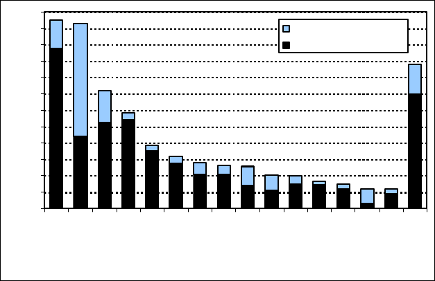
vehicles is distributed all over the world. Figure 13.1 shows the top 15 countries in
this industry during 2006. In addition to the top 15 countries, more than 25 coun-
tries contribute to the production of nearly 9 million vehicles [14].
Finally, the influence of the auto industry transcends the mere production of
goods. The auto industry is also a leader in innovation, playing a key role in the tech-
nology level of other industries and of society as a whole. By current estimations, the
industry invests about €85 billion in research and development per year, with several
manufacturers found among the leading top 10 corporations in the world [14].
13.1.2 Machining Processes in Automotive Production
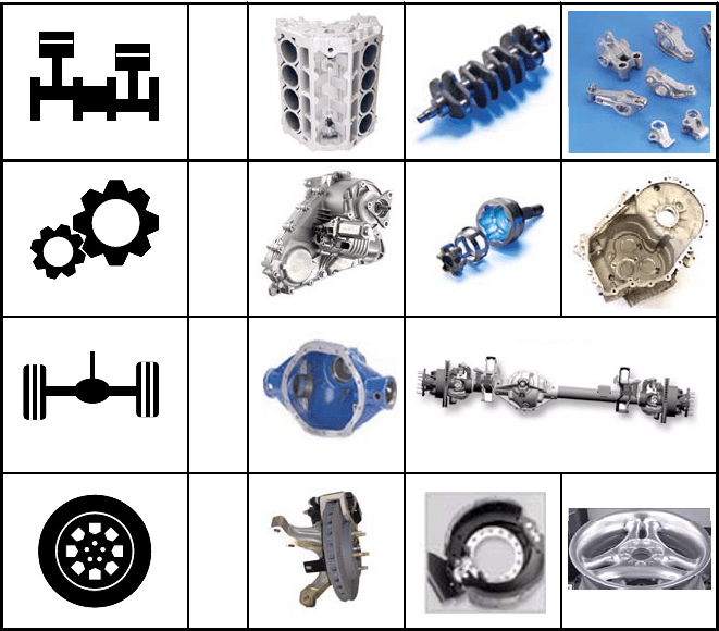
In the automotive industry, the general categories of products with significant
machining operations include: a) engine components, b) transmission and drive
components, c) axles and differential components and d) brakes and wheels.
In all cases, there is a significant amount of hole-making operations such as
drilling, tapping, reaming and boring. There is also an extensive use of milling
operations, such as face milling and pocket milling, and various turning opera-
13 Machine Tools for the Automotive Industry 423
tions. In some components such as crankshafts and camshafts, grinding operations
are needed. Special metal cutting operations such as turn broaching and broaching
are also applied for some components. The typical workpiece materials are forged
steels, cast irons and cast aluminium silicon alloys.
Figure 13.2 presents typical examples of automotive components produced by
first-tier suppliers such as Nemak
®
[8], Magna Powertrain
®
, Sisamex
®
, Delphi
®
and American Axle and Manufacturing
®
, among others. The following sections of
this chapter concentrate on machine tools for milling and hole-making operations.
In separate chapters of this book, technology trends associated with turning cen-
tres and grinding machines are discussed in depth.
13.2 Manufacturing System Architecture:
High Volume Production Versus Flexibility
In the automotive industry, there is a constant push to maintain the low unit cost
associated with high volume production, but at the same time to maintain flexibil-
Engines
Transmissions
and Drives
Axles and
Differentials
Brakes and
Wheels
Engines
Transmissions
and Drives
Axles and
Differentials
Brakes and
Wheels
Fig. 13.2 Automotive components that require machining operations
424 Ciro A. Rodríguez and Horacio Ahuett
ity. This need for flexibility comes from both a) the market demand shifts typical
of the automotive sector and b) manufacturing operation changes associated with
new product models. Clearly, the architecture of the machining system is designed
to suit the production demands and ranges from transfer lines to individual ma-
chines in job shop arrangements. The choice of architecture in turn determines the
structure of the machines that constitute the system.
13.2.1 Dedicated Machines
Dedicated machines are divided into linear transfer machines and rotary transfer
machines. The following sections explain and illustrate both types of dedicated
machines.
13.2.1.1 Linear Transfer Machines
The linear transfer machine or transfer line is an automated and interlocked group of
stations that includes machining, deburring, cleaning and inspection operations. The
whole transfer line must be designed and built as a unit. The various stations in the
transfer machine perform manufacturing operations on the product simultaneously.
By interlocking the machine stations and the material handing system, it is possible to
OP 10C
Pre-machine oil pan face and crakcase features,
finish-millin
g
manufacturin
g
lu
g
s
OP 10
Mill bank faces, mill oil pan face and crankcase
features, drill manufacturin
g
holes
OP 20C
Pre-machine bank & end faces, core drill cup plug
holes, drill oil gallery holes, de-flash cylinder bores
OP 20 Rough and finish-bore parent metal cylinder bores
OP 30C Washe
r
OP 30 Preliminary washe
r
OP 40C Leak test OP 40 Cylinder block heate
r
OP 50 Cylinder liner assembl
y
OP 60 Coolin
g
& stora
g
e s
y
stem
OP 70 Finish-mill, drill and tap bearin
g
cap seats
OP 80 Intermediate washe
r
OP 90 Bearing cap assembl
y
OP 100
Semi-finish mill, drill and tap oil pan face, finish
bore manufacturing holes
OP 110 Semi-finish mill, drill and tap end faces
OP 120
Drill and tap deck faces, drill and ream oil feed
and dip stick holes
OP 130
Finish-bore cup plug holes, mill, drill & tap
mounting
OP 140
Rough, semi-finish and finish-bore crank bore,
finish-bore water pump and dowel holes
OP 150
Rough, semi-finish and finish-bore cylinder bores
and finish-mill bank face
OP 160
Finish-mill front, rear & pan faces. Finish-bore
bank face dowels.
OP 170 Hone
OP 180 Final washe
r
OP 190 Cup plu
g
assembl
y
and leak test
Operations Order In Foundry Operations Order in Engine Plant
Fig. 13.3 Operations sequence for engine block machining in transfer line [1]
13 Machine Tools for the Automotive Industry 425
move a set of in-process products from station to station. As each product reaches the
end of the transfer line, all the manufacturing operations have been performed [11].
The first transfer machines used in the automotive industry date back to the
1920s, both in the US and the United Kingdom. However, it wasn’t until the 1960s
that automobile manufactures started to develop some degree of flexibility through
modularity in the transfer machines [11]. Through the years, transfer machine
developers have increased the modularity of these systems to accommodate the
shortening of product life cycle and market demand changes.
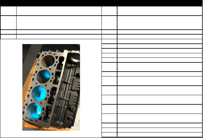
An example is presented in Fig. 13.3, which shows the typical operation se-
quence for engine block machining in a dedicated transfer line (the engine block
picture is for illustration purposes only). In this case, the transfer line is designed
to produce 650,000 engine blocks per year with a cycle time of 27
s. In general,
for the production of large automotive components such as engine blocks and
engine cylinder heads, a dedicated transfer line is recommended for volumes be-
yond 250,000 parts/year.
13.2.1.2 Rotary Transfer Machines
The rotary transfer machine, also known as the dial or carousel transfer machine,
is better suited for small automotive parts. These machines typically handle work-
ing volume envelopes up to 0.027
m
3
(300
×
300
×
300
mm). Rotary transfer ma-
chines can produce a large number of small automotive components, ranging from
100 to 550 parts/h. Considering a two-shift operation with a 75% uptime, these
machines can produce between 300,000 and 1,650,000 parts/year (according to
data from Kingsbury and [19]).
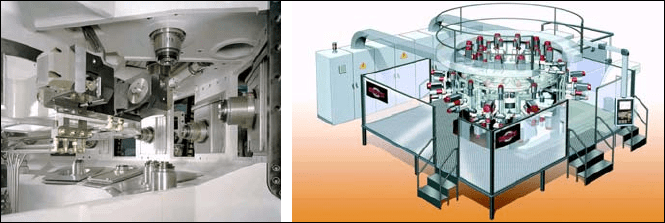
A typical design for a rotary transfer machine is presented by Gnutti
®
, which
produces a rotary transfer machine with a structure that allows 25 stations with up
to 33 high-speed spindles (see Fig. 13.4). This particular machine features 15
m/s
2
of axis acceleration.
An alternative design for rotary transfer machine is shown in Fig. 13.5. This
machine concept allows for 3 to 6 stations, with various configurations for each
station, such as horizontal, vertical, single spindle, double spindle and multi-head
Fig. 13.4 Modular rotary transfer machine, by Gnutti
®
