Lopez de Lacalle L.N., Lamikiz A. Machine Tools for High Performance Machining
Подождите немного. Документ загружается.

10 Parallel Kinematics for Machine Tools 355
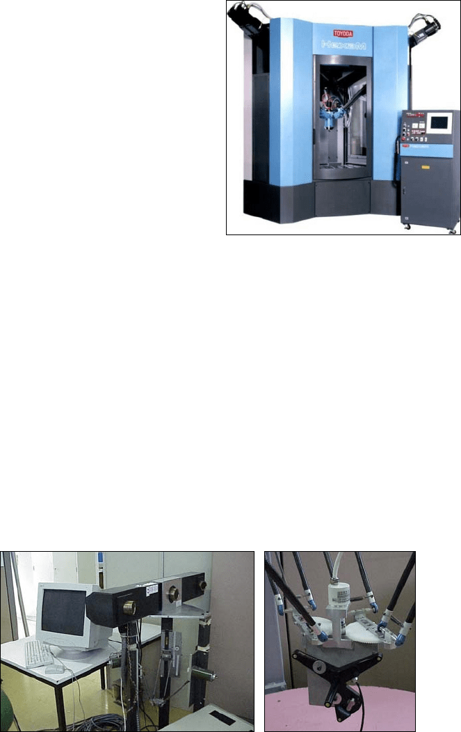
tion of a fully parallel structure, the HexaM™ (Fig. 10.11). The Cartesian posi-
tioning error is reduced from
±200
μm to less than 50
μm.
Figure 10.12 shows the calibration procedure of a 4 DOF parallel robot using
a 3D camera [2]. The camera “sees” a target of 4 points and obtains the position of
the target in the camera coordinate system.
The precision of the camera system is 0.25
mm, and a measuring range of 2
m
3
is
available. The main problem of this method is determining the position of the cam-
era coordinate system with respect to the machine coordinate system, but it can be
solved using transformations between coordinate systems and some additional
measurements. A calibration is performed using this methodology and the obtained
results improve the accuracy by 80%, giving precision values close to the precision
of the measuring artefact. A similar strategy is used to calibrate the Tricept™ PKM.
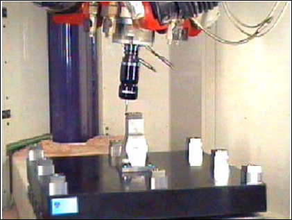
There is yet another method widely used to calibrate based on constraining the
motion of the TCP in one dimension by the use of test parts and probes
Fig. 10.11 HexaM™ machine,
by Toyoda
®
Fig. 10.12 Calibration of a 4-DOF PKM robot [2], the camera and targe
t
356 O. Altuzarra et al.
(Fig. 10.13). The principle of the calibration procedure can be explained as fol-
lows: a number of defined points are approached with a probe and a special NC
program on a calibration plate with some special towers whose sizes and position
relatively to the plate centre-point are exactly known (measured with a CMM). In
this procedure, the co-ordinates of these points and the corresponding strut length
values are determined by the machine control and stored into a file. This file is the
initial basis for calibration itself.
Other approach for calibration consists on machining a part in the machine to
be calibrated. Then the deviation between the real part and the theoretical part is
measured, usually in a CMM. From this information a calibration is performed.
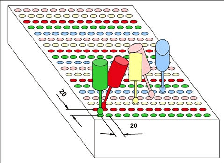
The approach from the ISW Institute [38] consists in a test-work piece, a paral-
lelepiped with an array of spherical holes (Fig. 10.14). Holes are arranged in a grid
of 20
×
20
mm. On a surface of 300
×
400
m this yields 273 holes. The workspace
is actually bigger than 300
×
400
mm, but this choice simplifies the handling of the
work piece. As the kinematical properties of the machine differ only slightly with
height (because the vertical and parallel direction of all drives), it is sufficient to
arrange all holes in one horizontal plane.
The holes have a diameter of 10 to 16
mm. This is chosen in order to ensure
good measurability with the CMM. The depth of the holes should be about half
their diameter. It is better to choose a bit less than that, because the depth may
vary in case of inaccuracies and it is more secure to be rather too high than too
deep. In case one mills too deep, the shaft of the tool might be damaged or de-
formed. Even elastic deformation without damaging the tool is unwanted, because
it leads to a wrong measurement.
The holes are machined with line wise varying spindle orientation (see
Fig. 10.14). The changing of spindle orientation improves the value of the meas-
urement information. The more the different poses (a pose is a combination of
position and orientation) vary from each other, the better. This rule is proven by
practice and has a clear theoretical background. The matrix that is used for the
method of steepest descent is better conditioned then. When all poses are almost
Fig. 10.13 Calibration with
a sampling plate
10 Parallel Kinematics for Machine Tools 357
the same, we will have a rank deficiency in the Jacobian matrix. As soon as the
rank is lower than the number of parameters we want to identify, the method fails.
The holes will be machined with a spherical cutter with changeable cutting
plates. Feed while milling will always be in z-direction. The revolution speed of
the spindle will be 1000
U/min at a feed rate of only 0.5
mm/min while finishing.
Coolant will be used to achieve a surface that is as smooth as possible and to re-
duce forces that would affect the position of the TCP.
Other research on this topic has been done by Chanal et al. [5,
6] with the
Verne machine.
A special combination of calibration strategies is being developed by Siemens
to calibrate the SKM 400 machine, a three translational axes horizontal machine
[45]. The calibration is done in two stages. The first one uses the laser tracker
LTD500 by Leica
®
. With this laser, the three Cartesian positions of the TCP are
obtained. With this information, a conventional calibration is performed, resulting
in a global machine precision of 35
μm.
Taking into account that the precision of the measuring system is around
15
μm, the remaining 20
μm are probably due to limitations on the error model
(elasticity, geometry). In that case two solutions are possible: (i) to improve the
error model (to take into account other effects or to improve the quality) or (ii) to
develop an additional compensation strategy.
This is being done by Siemens adding special functionality to the NC by means
of the space error compensation (SEC) strategy. With SEC the space errors can be
compensated simultaneously in the three spatial directions x, y, and z. The basis of
this system is measuring instruments that record the three coordinates of a points
simultaneously, such as the 3D-Laser Tracker.
First the NC moves the TCP to a defined target position in the working area, mak-
ing the assumption that the point defines ideal positions. Then, the actual positions
are determined at these discrete points by means of the Laser Tracker. By comparing
Fig. 10.14 Test work piece for calibration [38]
358 O. Altuzarra et al.
the actual position and the target position, the error can be determined for each meas-
uring point. The resulting 3D error table is then fed to the NC. This table enables
compensating the error in real time, based on a spatial, linear interpolation process.
By using this method the space error of the machine was reduced to a value of
15
μm, the same value as the external measuring system
10.5.3 Self-calibration Strategies
Concerning the self-calibration strategies, it is known that two or more redundant
information from sensors is enough to perform a self-calibration. Self-calibration
has the potential of (a) removing the dependence on any external pose sensing
information; (b) producing high accuracy data over the entire workspace of the
system, (c) being automated and completely non-invasive, (d) facilitating on-line
accuracy compensation and (e) being cost effective.
Researches have been working on self-calibration for a number of years, due to
the advantages over conventional calibration. Various self-calibration systems are
presented in [30]. All this approaches use the strategy of blocking joints and use
information of sensors to perform calibration
This approach, although permitting the calibration of the parallel structure, al-
lows bad automation, and requires sometimes the manufacturing of parts that can
give precision problems on the clamping procedure. This strategy of using redun-
dant sensor placed on universal joints is used in [52]. Using this approach all the
advantages of the self-calibration strategy can be obtained.
10.6 The Control of Parallel Kinematic Machines
The usual strategy nowadays is to use conventional strategies applied to PKMs.
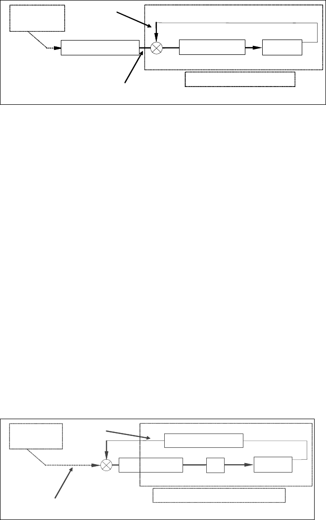
The most common scheme is the “inverse kinematics” one. The general principle
is summarised in Fig. 10.15: the trajectory generation module produces desired
Cartesian positions which are transformed into desired joint positions by the in-
verse kinematics module. Then a classical low level control loop is in charge of
servoing the joint positions.
There are two main reasons for this quasi-systematic use of such schemes:
• It is possible to use a different sampling time for the control loop (which re-
mains very simple here: it is motor control) and the computation of the inputs
(which needs in many cases a lot of floating point operations). These two tasks
can even be done by two different systems (e.g., amplifiers can take in charge
the low level position control while a computer does the inverse kinematics).
• For most parallel mechanisms, inverse kinematics is much easier to compute
than forward kinematics.
10 Parallel Kinematics for Machine Tools 359
One possible drawback of the method comes from the joint level control: it is
difficult to obtain a good accuracy in Cartesian space (which is often required)
with a control independent of the Cartesian configuration.
The second strategy is based on forward kinematics, as shown in Fig. 10.16.
The control loop is closed at the Cartesian level: the servoed variables are the one
really important for the user which is very appealing to get good accuracy in Car-
tesian space.
However, the drawback comes from the necessary computation of the forward
kinematics and the inverse of the Jacobian inside the control loop (that is: at a high
sampling rate). So, for a given control hardware, the sampling time will be bigger
in Cartesian control than in joint control.
Moreover, in the case of parallel robots, the computation of forward kinematics
cannot be expressed as an algebraic equation, in general (note that some mechan-
isms have this characteristic). The most common way to compute the forward
kinematic is based on numerical iterative techniques generally described above.
In the case of redundant machines, the control schemes should support (i) more
motors than DOF, or (ii) more sensors than DOF, and will probably be controlled
with schemes requiring you to get information from both the joint level (as in
schemes based on inverse kinematics) and the Cartesian level (as in schemes
based on forward kinematics) at the same control frequency.
Trajectory
generation
Machine Position Control
Inverse Kinematics
Position control in joint
Desired
joint
position
Actual
joint
position
Fig. 10.15 Classical control schemes with position control in joint space and trajectory genera-
tion in Cartesian space
Trajectory
generation
Machine
Position Control
Forward Kinematics
Position control in Cartesian space
Desired
Cartesian
position
Actual
Cartesian
position
J
−1
Fig. 10.16 Control in Cartesian space
360 O. Altuzarra et al.
10.6.1 Models Specific to Parallel Kinematics Machines
By definition, the mechanical architecture of a PKM differs from a serial one.
Even if control schemes developed for serial architectures are usable for PKMs,
they are far from giving good results.
To reach good accuracy and a high speed, some particularities have to be taken
into account during the controller design. The main difference between classical
serial architectures and parallel ones are recalled:
• The synchronisation of the axes has to be as perfect as possible. For example,
machining a straight line with a classical machine tool is very easy, but for
a PKM, the straightness of the machined line is the result of the quality of the
synchronisation between all actuators.
• The direct model, in general, does not exist in an analytical form. It has to be
computed in an iterative way. The inverse models often exist in an analytical
form. The control schemes used for PKMs take this consideration into account.
The open controller to be developed has to handle such considerations and also
the mathematical functions to compute these models.
• As intrinsically PKMs are able to reach higher speeds and accelerations, the
control must be able to handle these performances and to do so, to offer the
possibility to implement advanced controls like dynamic or predictive.
There are some specific problems to PKMs that influence the requirements of
control systems:
• The inverse kinematic model: for many simple PKMs (e.g., those based on
a Delta™-like principle, or Hexapods™, or HexaM™, or Hexaglide™, and so
on), the inverse kinematic model is rather easy to derive and to implement.
Such models, as no iteration processes appear during their resolution, are ex-
tremely easy to compute and should give no problem to control systems.
• Velocity relationships: the control system has to support linear algebra relation-
ships.
• Singular configurations: as already mentioned, singular configurations are de-
tected analysing the Jacobian matrix of the mechanism, so the control system
has to support linear algebra calculus.
• The forward kinematic model: writing the position relationships for a general
PKM gives usually a set of polynomial equations that are (in general) not solv-
able in a closed form. Usually, it is possible to resort to an iterative scheme to
work on the problem.
• Redundant machines: specific control strategies are required.
• Other cases: when inverse kinematics is not solvable without iteration (Space-
5H, Verne) or singular configurations are not visible resorting only to the Jaco-
bian matrix.
• The inverse dynamic model for advanced control: the use of this type of control
requires the computation of the inverse dynamic model of the machine. The aim
is to calculate, in an analytical way, the torques applied by the motors, as a func-
10 Parallel Kinematics for Machine Tools 361
tion of the position, velocity and acceleration of the motors. First of all, the Jaco-
bian matrix of the mechanism has to be calculated. This matrix permits having
a linear relationship between the velocity of the motors, and the velocity of the end
effector. In addition, the transpose of this matrix gives a linear relationship be-
tween efforts exhorted on the end effector and the torques applied by the motors.
There are two types of control suites for the PKM structure: the “dynamic con-
troller” and the model-based predictive controller, although both can be used also
for conventional machines (serial).
10.6.2 The Dynamic Controller
Some tasks performed by machine tools require fast motions and high dynamic
accuracy. In that case, the performance of the control has to be improved by tak-
ing into account dynamic interaction torques. This control is named computed
torque control or inverse dynamic control, and is based on the use of the dynamic
modelling of the machine. This control permits the linearisation and the decoup-
ling of the equations of the model, permitting a uniform behaviour in the whole
workspace of the machine. Thus, in order to implement such a control, the in-
verse dynamic model of the machine has to be calculated and implemented in the
control.
Although the dynamic control is suitable for conventional serial machines and
parallel kinematic machines, it becomes almost essential in the second category.
Usually, and due to the spatial distribution of the elements, the drives experience
a big variation in the commanded inertia. The traditional PID control structure can
manage limited variations in this inertia, and usually, the variations on the parallel
kinematic machines are bigger than these limits. This gives a situation of bad
trajectory follow-up, resulting in machining inaccuracies and instability problems.
Another problem related to parallel kinematic machines concerns the drive tun-
ing. The usual strategy is to tune the drives in the “worst” position. This position is
usually characterised by a lower stiffness, big axes inertia, etc. Sometimes, the
drive tuning is performed in such a way that a compromise in the entire working
volume is achieved. In both situations, the result is that the machine is optimised
in a usually small area of the working volume. In the rest of the position of the
working volume, the drive parameters could be increased or adjusted to obtain
a better machine performance.
Both problems can be minimised using the dynamic control. As a result, the
machine will have the same behaviour on the entire working volume, with in-
creased and optimised dynamic control and optimal machining precision.
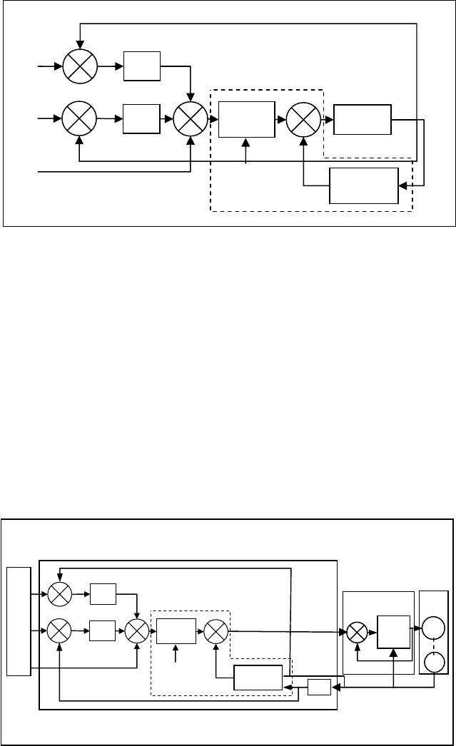
The inverse dynamic control consists of transforming a non-linear control prob-
lem into a linear one by using an appropriate feedback law (see Fig. 10.17). The
dynamic model can be written using two vectors directly used in the control. The
block diagram of the control is presented in the following figure.
362 O. Altuzarra et al.
In the ideal case of a perfect modelling and in the absence of a disturbance, the
problem consists in a linear control of decoupled double integrators, considering
that w(t) is the input control vector:
()
t=qw
(10.2)
The use of this control requires on-line calculation of the inverse dynamic model,
and a good knowledge of inertial, friction and mass parameters. The CPU has to be
sufficiently powerful to be able to make this computation. In the classical case, the
needs of such a control, in terms of the controller, are drives having current loop, i.e.,
drives able to control the torques applied by the actuators, and encoders. The velocity
and acceleration is calculated by the control itself using the position information.
Fig. 10.18 Implementation of the inverse dynamic control in the controller
..
.
Kp
Kv
)q(A
ˆ
Robot
)q,q(H
ˆ
q
d
q
d
q
d
q
q
+
+
+
+
+
+
+
-
-
q
Newton-
Raphson Alg.
.
Fig. 10.17 Block diagram of the inverse dynamic control
.
..
.
Kp
Kv
)q(A
ˆ
)q,q(H
ˆ
q
d
q
d
q
d
q
q
+
+
+
+
+
+
+
-
-
q
MC
Newton-
Raphson Alg.
d/dt
Current
Loop
M
s
NC
DRIVE
+
-
MOTOR
10 Parallel Kinematics for Machine Tools 363
In order to improve the behaviour of the control, some additional sensors can
be added. For example, an accelerometer or a force sensor can be placed on the
effector of the machine. The implementation of this inverse dynamic control in the
controller can be done as presented in Fig. 10.18.
This figure shows that all the calculations are done in the NC. It needs an input
that corresponds to the encoders of the motors, and an output allowing the control
of the torque of the motor through the current loop of the drive. As explained
previously, in order to extend the control, some additional inputs should be added,
as accelerometers or force sensors.
10.6.3 The Model-based Predictive Controller
Advanced controllers proposed to improve performances of production machines
will be based on the use of the dynamic model of the machine encountering for
inertial parameters. Efficient modelling can also take into account friction parame-
ters and elasticity. Model-based controllers are then implemented after the identi-
fication phase, which consists of estimating the model parameters.
The inverse dynamic model of machine tools composed of n moving links cal-
culates the motor torque vector
τ
(the control input) as a function of the general-
ised coordinates (the state vector and its derivative). It can be obtained from the
Lagrangian or Newton Euler equation:
=+
τ A(q) q H(q, q) (10.3)
where
τ is the (nx1) motor torque vector,
()
q,qq,
are the (nx1) vectors of general-
ised joint positions, velocities and accelerations respectively, A(q) is the (nxn)
inertia matrix, and
()
qq,H
is the (nx1) vector of the centrifugal, Coriolis, gravita-
tional and friction torques.
Equation 10.3 can be rewritten as a linear relation to a set of standard dynamic
parameters
X
s
:
= τχ
SS
D (q, q, q)
(10.4)
X
s
is the (13nx1) vector of standard dynamic parameters:
χ
⎡ ⎤
=
⎣ ⎦
j
S
T
jj jjjj j j jjjVjSj
XX XY XZ YY YZ ZZ MX MY MZ M Ia F F
(10.5)
It is composed for each link j of (XX
j
, XY
j
,
XZ
j
, YY
j
, YZ
j
, ZZ
j
) the 6 components
of the inertia tensor, (MX
j
, MY
j
,
MZ
j
) the 3 components of the first moment, (M
j
)
the mass, (Ia
j
) the total inertia moment for the rotor actuator and gears, (F
Vj
, F
Sj
)
the Coulomb and the viscous friction parameters.
For the estimation of the parameters of the dynamic model, usually
X is esti-
mated as the least squares (WLS) solution of an over determined (r x p) linear
364 O. Altuzarra et al.
system obtained from sampling and filtering the dynamic model along a trajectory
()
(t)(t)(t) q,q,q
:
()=τχρ+y W(q, q, q)
(10.6)
y is the (r x 1) measurement vector.
W is the (r x p) observation matrix.
ρ is the (r x 1) vector of errors.
The next steps can be divided in two stages:
1.
Identification procedure:
− exciting trajectories,
− signal acquisition,
− filtering,
− derivative estimation,
− weighted least computation.
2.
Control strategy:
− model parameters,
− controller parameters.
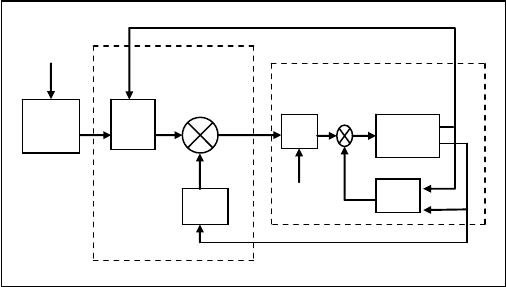
Figure 10.19 illustrates the model-based predictive control scheme.
Recent researchers are working on control algorithms without a model. Control
strategies based on dynamic models fit very well to parallel kinematic machine
tools. However, this approach depends mainly in the precise fitting of the dy-
namic model with the machine. During the machine tool life, small variations in
the operating conditions occur, such as ambient conditions, wear, and different
load conditions that lower the precision of the dynamic model. In this case, alter-
native algorithm models based on dynamic models with different precision levels
can be used.
Robot
Kv
)(
ˆ
qA
),(
ˆ
qqH
d
q
q
q
Γ
x
d
Γ
Non-linear compensation and
decoupling
Stabilizing linear
control
IKM
PFC
+
-
q
Fig. 10.19 Model-
b
ased control loop architecture
