Lopez de Lacalle L.N., Lamikiz A. Machine Tools for High Performance Machining
Подождите немного. Документ загружается.

406 J. Fernández and M. Arizmendi
Competition is strong in the aerospace industry, as in any other industry, and
the main goals are to drive down costs and/or reduce aircraft weight [7,
8]. These
two goals deserve to be considered in some detail.
12.4.1 The Drive to Reduce Aircraft Costs
The prevalent strategy for “small to middle range” aircraft is to cut costs. The
reason is that all aircraft companies build good and reliable aircraft and therefore
low price is a priority when it comes to buying a new aircraft.
The most straightforward strategy to cut costs consists of reducing process
times and the simplest solution for this is to increase feed speeds. However this
has two negative effects. On the one hand, a) it makes the cutting force to increase
(roughly in the same proportion as the feed) and b) it increases surface roughness.
However increasing cutting force also means increasing geometric error (a repre-
sentative example is the thin wall machining of aircraft structures). And increasing
roughness means poor surface quality. So increasing feed is not a good cost cut-
ting strategy.
Another strategy to cut costs consists of increasing both feed speed and spindle
speed, in the same proportion, so that feed per tooth (considering, for example,
a milling process) and therefore cutting force and roughness, do not increase.
The later strategy is known as high speed milling (HSM) and is being increas-
ingly applied in aerospace manufacturing.
Nevertheless increasing cutting speed presents the shortcoming of reducing tool
life, and therefore increasing associated tool costs. To solve this problem tool
coatings and more effective lubricant dispensation systems are being developed.
Although this also increases the tool related cost, on the whole this increase in cost
is compensated by the reduction in cutting times in many aerospace manufacturing
operations and this is the reason why HSM is gaining momentum in aerospace
manufacturing.
However the introduction of HSM implies running the spindle and the feed axis
of the machine at higher speeds than the ones used in ordinary speed machining
and this gives rise to some problems that imply the introduction of new or adapted
systems in the machine tools:
a) Dissipation systems for the heat produced in the bearings, the rotor and the
stator of the electro-spindles.
b) Automatic evacuation systems with high removal rates of chips.
c) Cutting fluid filters.
d) Mist handling, so that the high pressure cutting fluid does not impede the
operator’s ability to see the cutting zone.
e) Machine shielding to protect the operator from being hurt by chips at a high
speed.
12 Machines for the Aeronautical Industry 407
f) Feeding of the cutting fluid through the tool (otherwise tool tip cooling is not
efficient in HSM).
g) Number of tools in the machine magazine to cope with the reduced tool life in
HSM.
All these solutions have allowed HSM to be implemented by many component
suppliers.
12.4.2 The Drive to Reduce Aircraft Weight
The prevalent strategy for “long range–big capacity” aircrafts is not to cut costs, as
in small to middle range aircrafts (see Sect. 12.4.1). In the former, the number of
constructors is smaller and competition is not so strong, so price is not as impor-
tant when it comes to buying a new aircraft. Here the main issue is to minimize
fuel consumption, and thereby reduce aircraft weight. There are two ways to re-
duce aircraft weight:
a) Improving performance of the aircraft materials or introducing new material
components (the same mechanical properties with less weight) and
b) Reducing the mass of the aircraft components.
The role of the components supplier is apparently a secondary one, since the
first approach concerns the “materials department” and the second one, the “de-
sign and engineering department” of the main contractor. Nevertheless, the com-
ponent supplier actually plays an important role by working very closely with both
departments in researching new solutions. Thanks to main contractors and compo-
nent suppliers today’s aircrafts are lighter and relatively cheaper.
But besides aircraft cost and weight reduction, there are other topics that mark
the way machine tools are designed and built. One is component precision that
will be considered in the next section.
12.4.3 The Drive for Aircraft Component Precision
Precision is another “hot topic” in aerospace. It can be tackled mainly by:
a) Reducing the number of component set-ups on the machine, and
b) reducing component and machine distortions during machining.
12.4.3.1 Reducing the Number of Set-ups to Improve Precision
Component set-up on the machine table not only takes time but it is also a main
source of component errors (parallelism, perpendicularity, position …). Therefore, to
improve precision, a good strategy is to reduce the number of set-ups to a minimum.
408 J. Fernández and M. Arizmendi
For machining a particular component, the number of set-ups, increases with its
geometrical complexity, but decreases with the number of machine tool CNC
axes. Since a large amount of aerospace components are very complex in geome-
try and need more than one set-up, one strategy for improving precision consists
of changing from a 3-axis machine to a 4 or 5-axis machine. Actually, this is the
trend observed in many manufacturing subcontractors. 4/5-axis machines are more
expensive and more difficult to program and control than the 3-axis machines.
Nevertheless this extra cost is worthwhile in many components due to the im-
provement in precision.
Another advantage of the 4/5-axis machine is that machining can be done in
many more possible ways and therefore better machining strategies can be selected.
For example a 5-axis machine can perform an operation with a shorter overhang
length tool than a 3-axis machine, and therefore with greater rigidity and precision.
12.4.3.2 Diminishing Distortion to Improve Precision
Apart from minimising the number of set-ups, which has just been considered,
diminishing component and machine distortions during machining is another issue
that allows improving precision and this will be now considered.
As was already mentioned (Sect. 12.2.1), structure components are usually ma-
chined out of large aluminium plates and, since the component geometry is usually
strongly non-symmetrical, the natural equilibrium of the aluminium plate internal
stresses is strongly broken and this generates component distortion. One way to
minimize this danger is by checking the “as received” plates for internal stresses.
Another issue is the differences found in the shapes of components of the same
batch caused by the changing thermal status of the machine tool over time as
a result of different sources such as the warming up period of the machine or even
difference between day and night temperatures in the shop. These thermal gradi-
ents give rise to distortions in the machine and generate differences in the compo-
nent shape. There are two strategies to solve this problem: a) keeping the machine
thermal status constant and b) estimating and subsequently correcting the state of
distortions in the machine. Strategy a) demands good design and sometimes the
installation of cooling devices close to the machine’s thermal sources and repre-
sents the simplest solution. Some machine builders address also strategy b) by
providing intelligence to the machine tool so that distortions can be estimated and
corrected automatically. This topic and the improvement of the machine dynamics
are probably the two most crucial research points for machine tool builders today.
12.5 Machine Tools for Aeronautical Components
Having considered how machine tools and machining methods have evolved to
improve the price, weight and precision of aeronautical components, we may now
12 Machines for the Aeronautical Industry 409
address the evolution of machine tools and the machining methods related to the
three main classes of components, structures, engines and accessories.
12.5.1 Machine Tools for Machining Aeronautical Structures
As was already mentioned (Sect. 12.2.1) aeronautical structures are geometrically
complex and are manufactured mainly out of aluminium plates by removing
a large amount of material (sometimes up to 90%). This large ratio aluminium
plate mass/components mass, the so-called “buy to fly” ratio, implies converting
a huge amount of raw material in chips and this implies considerable costs.
That geometrical complexity came into play little by little in aerospace gaining
ground to components that initially were made out of many simpler parts joined by
screws, rivets or welds. The disadvantages of the joining process were lower com-
ponent strength and the amount of time spent in the assembly of the component.
The complexity of the parts geometry demands a 4/5-axis machining centre. How-
ever tolerances are not an issue (around 0.2
mm).
As is mentioned in Chap. 1, three configurations are common in 5-axis machin-
ing centres, namely:
a) LLLRR, where the spindle head has two rotary axis,
b) RLLLR, with a rotary table and a swivelling spindle head and
c) RRLLL, with a double rotary table.
Besides the rotary and/or swivelling movements, all configurations also have
3
linear axes (X, Y, Z) between the head and the table.
The best configuration for a particular component will depend on its size
which, for these components, varies considerably (between 1 to 12
metres).
12.5.1.1 The LLLRR Configuration
For machining large structural parts such as wing and fuselage skins, frames and
stringers, LLLRR machining centres with three Cartesian axes (X, Y, Z) and two
rotary axes (A, C) at the spindle head are used. The C-axis rotates the head while
the A-axis tilts it.
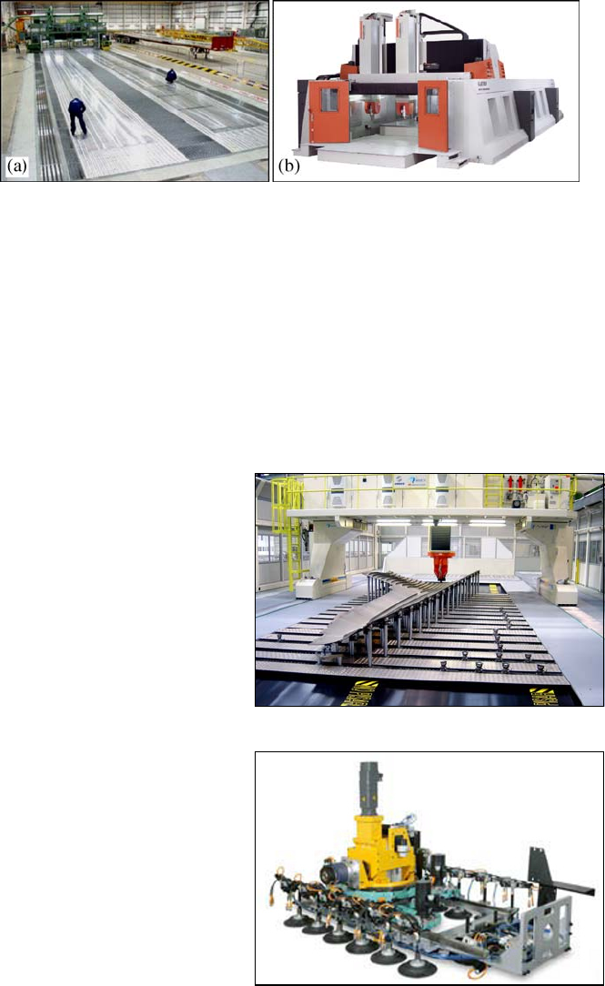
This axes configuration is typical of large “gantry” machining centres, such as,
for example, the dual Spindle gantry mill from Henri Liné
®
(Fig. 12.4a) and the
Gantry TS machining centre from Handtmann
®
(Fig. 12.4b). Both have two moving
vertical spindles so that either of the two components can be machined simultan-
eously or one component can be cut by two tools at the same time. In both cases an
increase in the material removal rate, and hence in productivity, can be achieved.
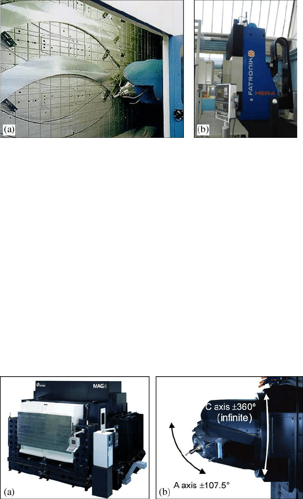
Mtorres
®
has developed the 5-axis gantry milling machine TorresMill
(Fig. 12.5) with a flexible tooling for the accurate positioning of parts for the rout-
ing and drilling of skin panels, stringers and frames.
410 J. Fernández and M. Arizmendi
Fig. 12.4 a Machining of large wing skin on a dual Spindle Gantry mill from Henri Liné
®
.
b Handtmann
®
Gantry TS with a twin spindle
A more specific machine has been developed by Fatronik
®
(Fig. 12.6), which is
a crawling portable robot for drilling large frame panels and structures for fuse-
lages and wings. The robot has the capacity of fixing itself to the frame panel by
vacuum cups so that drilling can be performed. Compared to the previous ma-
chines, it provides flexibility and portability.
As was said before, machining of structural components generates huge
amounts of chips that have to be evacuated from the working area. To solve this
Fig. 12.5 TorresMill from
MTorres
®
for the routing and
drilling of aerospace structural
components
Fig. 12.6 Crawling portable
robot from Fatronik
®
for the
drilling of large panels and
structures of fuselage and wings
12 Machines for the Aeronautical Industry 411
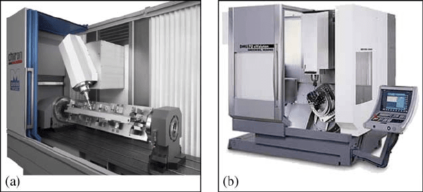
problem, horizontal machining centres with a travelling column, as the one shown
in Fig. 12.7a, are commonly used. As in previous machines, the tool has two ro-
tary axes (A, C). This configuration allows high chip volumes to be evacuated
through a chip conveyor placed between the column and the vertical frontal panel
where the part is placed.
Parallel kinematics has a niche for aeronautical structures and some 5-axis hy-
brid machining centres with a travelling column have been developed. As an ex-
ample, the Hera from Fatronik
®
(Fig. 12.7b) has a 3 axes parallel kinematics mod-
ule implemented in 2 serial axes for the machining of structural monolithic parts.
For medium size structures, 5-axis horizontal machining centres, with an
LLLRR configuration, are common. As an example, Fig. 12.8 shows the MAG4
5-axis machining centre from Makino
®
. It has two A/C rotary axes at the spin-
dle head where the A-axis rotates by +/–107.5º and C, by 360º allowing 5 side
machining.
Fig. 12.8 a Five–axis horizontal machining centre MAG4 from Makino
®
. b A detail of the two-
axis tilt/rotary spindle head
Fig. 12.7 a Horizontal machining centre Aerostar from Forest Liné
®
. b 5-axis hybrid machining
centre Hera from Fatronik
®
412 J. Fernández and M. Arizmendi
12.5.1.2 The RLLLR Configuration
So far, only the LLLRR configuration has been considered. This machine type is
the most adequate for large components that do not require high precision but it
cannot be employed to machine precise parts because the two rotary axes cannot
provide enough stiffness to the tool. In this case, one of the rotary axes is trans-
ferred to the table and the tool stiffness, now with only one axis, can provide
enough stiffness to fulfil the demanded precision in the component. This is the
RLLLR configuration.
Medium-size components (such as wing ribs) usually demand more precision,
and for this type of part machines with a RLLLR configuration are the right
choice. Among the different possibilities of this configuration the most common
one is a machine with a 360º rotary A-axis at the table and with a swivelling
B-axis at the spindle head.
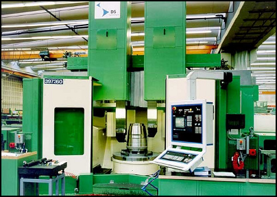
One example of this type of machines is the Mill Series from Chiron
®
. It is
a 5-axis machining centre that can be seen in Fig. 12.9a. The combination of
a 360º horizontal rotary (A) table and the (+/–100º range) swivelling (B) of the
head allows complex parts, such as the one in the figure, to be machined in only
one set-up.
Fig. 12.9 a Mill Series from Chiron
®
with a B swivel head and A rotary table. b DMU 70
eVolution with a swivel rotary table from DMG
®
12.5.1.3 The RRLLL Configuration
For small structural components, the configuration RRLLL with a swivel/rotary
table is commonly used.
As an example of this configuration, Fig. 12.9b shows the vertical 5-axis ma-
chining centre DMU 70 eVolution. It has a table with a 360-degree rotary C-axis
and a swivelling B-axis. It is a very flexible machine but it has the drawback of
a small working area that limits the component size that can be machined.
12 Machines for the Aeronautical Industry 413
As far as structures are concerned there is an emerging process of joining
structural assemblies to make larger components: the so-called “friction stir
welding” (FSW). FSW is easier and faster to implement in the shop than the
other structural joining processes such as riveting or welding. It strongly re-
duces assembly time and eliminates rivets, thereby, reducing assembly costs
and providing stronger and lighter joints. It is believed that, in the future, FSW
will replace most of the rivets in assemblies of cabins, fuselages, wings and
engines.
12.5.2 Machine Tools for Machining Engine Components
These components are machined out of castings or forgings of titanium alloys,
HRSA and steel and undergo long machining operations to reduce weight. How-
ever, in contrast to structures, tolerances are demanding.
The machine tools employed to manufacture different engine components are:
a) vertical lathes, machining centres of b) RRLLL and c) RLLLR configurations
and d) the newly introduced multi-function or multi-tasking machines. All are
described below.
12.5.2.1 Vertical Lathes
One of the engine components is the ring case (or housing), that can be as big as
2500
mm in diameter and needs external and internal turning operations plus mill-
ing operations to reduce weight. Commonly, the turning operations are performed
in lathes and then the component goes to a machining centre for the thinning
operations.
For shaping the internal and the external diameters of the ring type engine cases
vertical lathes are employed (Fig. 12.10).
Fig. 12.10 Vertical turning
lathe Contumat VCE from
Dörries Scharmann Tech-
nologie
®
for turning and
b
oring jet engine parts
414 J. Fernández and M. Arizmendi
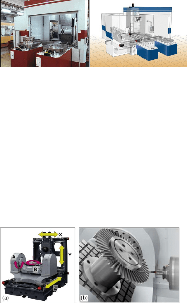
Fig. 12.11 Five-axis horizontal machining centre Starragheckert
®
ZT-800
For the subsequent weight reducing operations in engine cases, RRLLL and
RLLLR configurations are commonly used. Apparently the machining centres are
similar to the ones used for small and medium sized structural components but
there are some differences because, due to the difficult-to-cut materials used in
engine parts, much lower cutting speeds are employed and, as a consequence,
main spindles with high torque at low speeds are used instead of high speed spin-
dles that are commonly used for structural component machining.
As an example, Fig. 12.11 shows the 5-axis horizontal machining centre
Starragheckert
®
ZT-800, that has an RLLLR configuration. The head spindle can
move in the Y, Z and A axes and the table in the X and B axes. The machine has
two loading/unloading stations to save cycle times.
12.5.2.2 Machining Centres with the RRLLL Configuration
For the machining of smaller engine components such as blisks and impellers, ma-
chining centres with swivelling and rotary table (RRLLL configuration) are used.
The three linear axes (X, Y, Z) can be placed either at the tool side or distributed
between the tool and the table.
Fig. 12.12 a 5-axis horizontal machining centre NMH10000 DCG from Mori Seiki
®
. b Machin-
ing of a blisk
12 Machines for the Aeronautical Industry 415
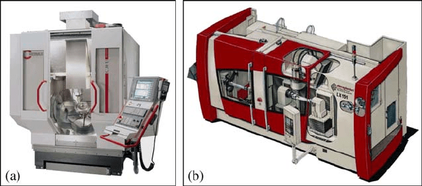
Fig. 12.13 a C30 U from Hermle
®
. b LX 051 from Starragheckert
®
for turbine blades machining
Figure 12.12a shows the NMH10000 DCG, a 5-axis horizontal machining centre
from Mori Seiki that has a box-in-box frame architecture and a table with
a linear Z axis, a B rotary axis and an A swivelling axis. Figure 12.12b illustrates
how the machining of a blisk is performed.
Figure 12.13a shows another RRLLL configuration, a 5-axis vertical machining
centre C30 U from Hermle
®
, with a gantry design instead a box-in-box frame. The
tool travels in the three (X, Y and Z) axes and the component is placed on a swivel-
ling (A) and rotary (C) table. The A-axis swivelling range is of +/–115º.
12.5.2.3 Machining Centres with the RLLLR Configuration
For the machining of turbine blades, as well as for case thinning, machining cen-
tres with an RLLLR configuration are the best choice. In Fig. 12.13b, a 5-axis
vertical machining centre from Starragheckert
®
can be observed where the blade
that is held between centres can rotate in the A-axis while the spindle head swivels
on the B-axis (+/–50º).
12.5.2.4 Multi-function or Multi-tasking Machines
As seen above, some components such as the engine housings need to go through
a vertical lathe, for external and internal turning, and later through a machining
centre for weight reducing operations. This procedure has a time penalty since the
component has to be loaded and unloaded in both machines.
To solve this problem new hybrid machines known as multi-function or multi-
tasking machines have been shown in recent machine tools fairs. One representa-
tive example is a new DMG hybrid machine (100% lathe and 100% machining
centre according to the builder) shown in Fig. 12.14a which is designed to ma-
chine engine components such as compressor housings, blisks and turbine blades
in only one set-up.
