Lopez de Lacalle L.N., Lamikiz A. Machine Tools for High Performance Machining
Подождите немного. Документ загружается.

6 Machine Tool Performance and Precision 233
nents (guide and counterguide) generates effects, such as stick and slip, that can
originate difficult to control vibrations. Thus, a precise guiding system not only
has to be accurate in the construction, but must also present smooth motion.
Hence, the design of guiding systems should accomplish two objectives, minimum
and constant friction coefficients.
6.2.3.3 Abbe’s Principle
This basic principle of metrology states “the length to be measured and the measuring
scale must lie on the same axis”. In conventional machine tools, many linear motion
systems do not satisfy Abbe’s principle because the motion axis and the machine
element (its reference point or its centre of gravity) do not lie on a single line.
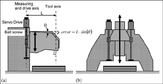
In Fig. 6.7 two different machine tool designs are presented, Fig. 6.7a shows
a C-frame with a single ball screw column. As can be observed, the tool axis line
and measuring line are separated; Abbe’s principle is thus not satisfied and there-
fore the angular deflection is translated into a displacement error at the tool. In
Fig. 6.7b a double column and twin ball screw is shown. In this case, the distance
between the tool axis and each ball screw axes compensate the angular deviation
effect on the linear axis. This is, obviously, a more costly solution, but the ma-
chine precision is much higher.
Fig. 6.7 Two different machine designs. a With Abbe’s error. b With Abbe’s error reduction
6.2.3.4 The Position Measurement
A direct measuring system, free of external perturbations or noises, is always
better than an indirect measuring one. The latter needs some geometrical parame-
ters that may vary due to sources of error. A classical example of this principle is

234 A. Lamikiz, L. N. Lopez de Lacalle and A. Celaya
the use recommendation of linear encoders instead of encoders to measure the
position of linear axes.
Most of the measuring devices for machine-tools operate using the principle of
photoelectric scanning, which is a contact-free method, so the measuring systems
are free of wear. These systems use light scanning devices, consisting of a light
source projected to two graduations with equal grating periods. One of the gradua-
tions: the scanning reticle is moved relative to the other: the scale reticle. When
the light passes through a grating, light and dark surfaces are projected to a photo-
electric sensor. There are two limit positions: first, when the gratings are aligned,
light passes through and the photovoltaic cells generate the maximum voltage
value. On the other hand, if the lines of one grating coincide with the gaps of the
other, no light passes through and the photovoltaic cells signal is minimum. The
resulting signal of the relative motion between the scanning and the scale reticle
generate nearly sinusoidal output signals.
There are two types of photoelectric measuring systems, depending on the scale
reticle. First, if the scanning reticle is a disk, the measurement device is called
a rotary encoder or simply an encoder. Rotary encoders can be used for the angu-
lar measurement of rotary motions such as NC rotary axes, tilting tables or angular
metrology measurements. On the other hand, if the scanning reticle is a linear
scale, the measurement device is a denominated linear encoder or simply a linear
scale. Both linear and rotary encoders can be divided into absolute and relative
encoders. The absolute encoders use a scale graduation formed from several
graduations or code tracks where each possible position creates a unique code.
Thus, the position is read directly and there is no need to find a reference position.
The relative encoders use a constant grating period scale, and the position is
measured relative to a reference position. The resolution of the relative encoders is
higher than the absolute ones and it is the most typical measuring device for high
precision machine tools.
The resolution of the relative encoders depends mainly on the period of the
grating scale. The smaller the period of the grating structure is the higher is the
resolution. In addition, the measurement precision depends on the mounting toler-
ance between the scanning and the scale reticle. Actually, typical grating periods
Fig. 6.8 a Rotary encoders. b Photoelectric scanning for a rotary and linear encoder. (Courtesy
of Fagor Automation
®
)

6 Machine Tool Performance and Precision 235
are below 20
μm and, for high precision applications, there are linear encoders
with 4
μm grating periods. In addition, the scanning reticle can be divided in sev-
eral scanning grids offset from each other. A photocell is assigned to each scan-
ning field and a different sinusoidal electrical signal is obtained from each one.
Thus, each grating period can be divided interpolating the different electrical sig-
nals from each photocell and the resolution of the measurement can be improved
up to 0.1
μm for high precision applications. In Fig. 6.8, both a rotary and a linear
encoder photoelectric scanning principle are presented.
In Fig. 6.9 two measuring solutions are presented. The solution based on the en-
coder directly measures the angular position of the ball screw, placed on the oppo-
site side to the joint between the drive and the ball screw. Using this data, the posi-
tion of the axis can be obtained, calculating the relationship between the linear axis
motion with the ball screw rotation, which is defined by the ball screw lead. How-
ever, the measurement is affected by numerous sources of error. Thus, the encoder
cannot detect the ball screw deformations due to thermal or load effects. On the
other hand, backlash of the ball nut is not detected either. In other words, the en-
coder cannot detect what happens in those elements placed after the drive system.
Contrarily, if a linear scale is installed between the table and the machine struc-
ture, the linear movement is measured directly. This measurement is independent
of the ball screw features (diameter and lead) and its deformations. Thus, it is
again a more costly but very much precise solution.
6.2.3.5 The Principle of Error Correction
The global precision after assembly is usually below the required precision for the
machine. This fact leads to use compensation techniques to correct and minimise
those errors that can be measured by advance measuring instruments such as laser
interferometers. Corrections are implemented in the machine CNC with the aim of
achieving the target position for the tool centre point. This principle or method may
seem an easy solution, because target positions can be obtained without the need to
build a very precise machine. However, it is false because there is a limit of accu-
racy compensation; low-precision machines will not significantly improve the pre-
cision by compensating the errors and will never become high-precision machines.
Fig. 6.9 a Encoder based measuring system. b Linear scale based measuring system
236 A. Lamikiz, L. N. Lopez de Lacalle and A. Celaya
In this respect, different types of errors can be distinguished:
• Repetitive errors, which can be predictable and, therefore, compensated by the
machine CNC. Usually, the geometric errors are in this group. A repetitive er-
ror is an error, but it is not really an uncertainty.
• Non-repetitive errors, which are variable with temperature, force, vibration or
other factors. These errors cannot be compensated because error value is un-
known. However, a lot of research in modelling, monitoring and control tech-
niques has been done. Through these techniques, thermal deformation or vibra-
tions errors may become predictable and consequently compensated.
• Random errors. Despite the current models there are a lot of divergences be-
tween reality and design that are impossible to be estimated. Therefore only
statistical treatments can be used with them.
6.2.3.6 Machine Tool Position Control
Once the machine is designed and built with the required precision, it is necessary
to tune the control of its motions. The first important fact is that it is impossible
to achieve a precise motion with low precision hardware.
Machine control must be designed under the filter effect principle, based on
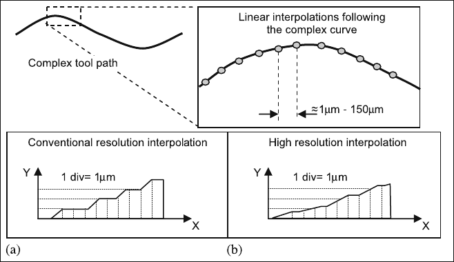
noise correction and obtaining precise and smooth motion. One of the noise
sources is the resulting linear interpolations of complex curves. CAD files are
usually defined with high order NURB curves. These curves are defined with
a relatively small quantity of points; nevertheless the geometry is well defined
Fig. 6.10 Conventional (a) and high resolution interpolation (b) for a sequence of linear inter-
polations
6 Machine Tool Performance and Precision 237
due to the mathematical definition of the shapes. However, the NC program
generated by CAM systems is usually based on small linear interpolations. As
a result, a double negative effect is introduced. First, the toolpath is not exact,
although the deviation between the toolpath and the exact curve can be con-
trolled by the CAM software. Second, the sequence of lineal interpolations re-
sults in a non-smooth toolpath which can result in axis drive instability and,
finally, in machining vibration.
Modern machine tool controls incorporate specific functions to minimise the
discontinuity effect deriving from the linear interpolation. Thus, advanced jerk
control functions are integrated in the CNC for controlling the feed rate at work-
piece corners. Jerk control results in a smooth variation of acceleration which
results in a smooth motion without any instability or shocks. On the other hand,
the resolution of interpolations has been improved significantly during recent
years. In Fig. 6.10 conventional and high resolution interpolation schemes are
presented. A relatively rough interpolation that leads to a poor surface finish
(Fig. 6.10a) is presented. In contrast to that, Fig. 6.10b shows a high resolution
interpolation that enhances surface finishing.
6.2.4 Error Propagation
Machine tools are spatial mechanism with joints that can be modelled as kinematic
pairs. Depending on the type of machine the kinematic model is different, and can
be represented by a “bar and nodes” scheme like any mechanism. This model
includes rotary and prismatic joints.
A X
i
Y
i
Z
i
coordinate system is going to be fixed on each element of the mecha-
nism; hence the position of the element will be fully defined by the X
i
Y
i
Z
i
origin to
the absolute reference system X
0
Y
0
Z
0
and the rotation of the X
i
, Y
i
and Z
i
axes with
respect to the X
0
Y
0
Z
0
coordinate system. To obtain the position of an element
placed at the end of the mechanism (in a machine tool, the cutting tool is the ele-
ment) a coordinate system must be associated to it at the tool centre point.
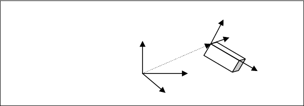
A known method to represent the relative spatial position of a rigid body with
respect to a given coordinate system is based on a 4
×
4 matrix, the so-called ho-
mogeneous transformation matrix [10]. The first three columns of the matrix (see
Fig. 6.11) represent the unit vectors of the rigid body reference system X
i
Y
i
Z
i
with
respect to the absolute reference system. The fourth column indicates the position
of the X
i
Y
i
Z
i
origin with respect to the reference system.
Using homogeneous transformation matrices, any element point refereed to the
local system X
i
Y
i
Z
i
can be easily obtained with respect to the X
0
Y
0
Z
0
reference
system as follows:
[]
⎪
⎭
⎪
⎬
⎫
⎪
⎩
⎪
⎨
⎧
=
⎪
⎭
⎪
⎬
⎫
⎪
⎩
⎪
⎨
⎧
i
i
i
z
y
x
T
z
y
x
0
0
0
(6.3)
238 A. Lamikiz, L. N. Lopez de Lacalle and A. Celaya
¸
¸
¸
¸
¸
¹
·
¨
¨
¨
¨
¨
©
§
1000
zzyx
yzyx
xzyx
kkk
jjj
iii
T
G
G
G
X
0
Y
0
Z
0
X
i
// (i
x
, j
x
, k
x
)
Y
i
// (i
y
, j
y
, k
y
)
Z
i
// (i
z
, j
z
, k
z
)
G
x
, G
y
, G
z
Fig. 6.11 Homogeneous transformation matrix to define the element spatial position
To represent a spatial manipulator like a machine tool, a homogeneous trans-
formation matrix is formulated to pass from one element to the next. Elemental
matrices are multiplied successively to obtain the unique homogeneous transfor-
mation matrix which can calculate the position of the tool (placed at the end of the
manipulator) with respect to the reference coordinate system. Thus, the global
transformation matrix T
4x4
of the machine and the tool is obtained.
In the case of machine tools, the tool centre point or TCP is the tool reference,
placed just at the tool tip, and the Z
tcp
axis usually matches the tool axis. There-
fore, the global homogeneous transformation matrix of a machine tool gives the
position of the TCP system (X
tcp
Y
tcp
Z
tcp
). This matrix is a function of the machine
geometrical parameters and the position of the degrees of freedom (machine axes).
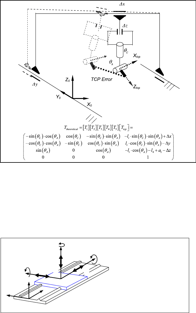
For example, in Fig. 6.12 a five-axis gantry type high speed milling centre and its
kinematic model are shown. This machine presents three translational axis (X, Y and
Z) in the ram, and two rotary axes (A and C) in the headstock. Once the model is de-
signed, a reference coordinate system (X
0
Y
0
Z
0
) fixed to the machine bed is specified.
To obtain the homogeneous transformation matrix of the whole machine, different
reference systems (not shown in the figure) are set at each structural component.
Multiplying each transformation matrix from one element reference to the following
one [T
i
], the resultant homogeneous transformation matrix [T
th
] is obtained, as is
shown at the bottom of Fig. 6.12. The terms of this matrix depends on the position of
the machine tool axes (
Δ
x,
Δ
y,
Δ
z,
θ
A
and
θ
C
), geometrical parameters of the machine
structure defined as a
1
or l
4
, and finally, on the tool length, defined as l
t
.
In the same way, an error in any machine component can be considered in the
kinematic model as a new parameter. In Fig. 6.12, the theoretical and real kine-
matic schemes are presented. As shown, the position of the tool tip referred to the
(X
0
Y
0
Z
0
) coordinate system is much more difficult to evaluate as all the errors of
the machine elements and joints have to be considered.
The complexity of the homogeneous transformation approach is derived from
the large number of errors that must be considered in each elemental transformation
[8, 18]. For example, considering a linear guide, the transformation matrix gives the
motion of a coordinate system set in the carriavge with respect to a reference system
set on the guide.The ideal linear guide results in an easy translational matrix, in-
cluding the constant values a, b and c dependent on the geometry of the guide and the
6 Machine Tool Performance and Precision 239
Fig. 6.12 Kinematic models of a perfect and real five axis gantry machining centre
Δ
x motion of the slide. But if errors are considered, the resulting matrix introduces
several translation and rotation terms (see Fig. 6.13). Error values noted as
δ
x
,
δ
y
,
δ
z
correspond to the linear positioning errors, whereas
ε
x
,
ε
y
and
ε
z
are the roll, pitch
and yaw errors. These errors are variables for each position of the guide and have to
be measured previously. Thus, comparing ideal and general matrices, the number of
parameters significantly increases.
X
0
Y
0
Z
0
Z
i
X
i
Y
i
G
x
G
z
G
y
H
x
H
y
H
z
¸
¸
¸
¸
¸
¹
·
¨
¨
¨
¨
¨
©
§
'
1000
1
1
1
zxy
yxz
xyz
c
b
xa
Ti
GHH
GHH
GHH
General Transformation matrix
¸
¸
¸
¸
¸
¹
·
¨
¨
¨
¨
¨
©
§
'
1000
100
010
001
c
b
xa
Ti
Ideal Transformation matrix
Fig. 6.13 Ideal and general homogeneous transformation matrix for a linear guide
240 A. Lamikiz, L. N. Lopez de Lacalle and A. Celaya
Y
Z
X
E
r
=
H
R
Y
X
Case a: Sensitive error direction
H
R
Y
X
Case b: Non ensitive error direction
E
r
<<
H
s
-
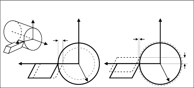
Fig. 6.14 Sensitive and non-sensitive error directions for a conventional turning operation
Despite this complexity, homogeneous transformations including errors of each
element result in an outstanding tool to study and improve the machine precision.
The influence of each error in the tool position could be checked (“error map-
ping”), concluding whether a specific error is important and worth working on to
reduce it. On the other hand, it is useful to check whether errors are in a sensitive
or a non-sensitive direction.
A direction is called sensitive when an error along it propagates directly or is
even amplified at the tool tip. A non-sensitive direction is one where errors slightly
affect at the tool tip. In Fig. 6.14 a typical example of sensitive and non-sensitive
directions are presented. Here, the same error value ε is introduced in the tool for
a conventional turning operation. In the first case, the error is introduced in the
radial direction, resulting in a similar workpiece error E
r
. However, if the same
error value is introduced in the tangent direction, the resulting error E
r
is much
lower than
ε
. In this case, the radial is a high sensitive direction and consequently
errors in that direction are the first to be reduced.
6.2.5 Thermal Errors
Thermal growth of machine tool structure and workpieces is, in general, a well-
known effect. There is a general understanding that temperature variations can
affect machine dimensions, consequently affecting its precision [3]. Nonetheless,
over the years, few machine tools have been designed to minimise thermal growth
effects. However, today some users are starting to keep the workshop temperature
at 20ºC commonly by air conditioning.
The size of solid elements depends on the temperature and most materials
expand or contract linearly with it; graphite is an exception being practically
6 Machine Tool Performance and Precision 241
stable for thermal variations. The increment of a linear length can be calculated
as:
0
LTL ⋅⋅Δ=Δ
α
(6.4)
where ΔL is the length increment, ΔT is the temperature variation,
α
is the thermal
expansion coefficient and L
0
is the initial length of the object. This equation con-
siders constant thermal expansion coefficient and uniform temperature along the
linear object, but it gives a reasonably good approximation of the thermal growth
of a component.
In view of this formula, the variation of length can be minimised if the lengths
of the element, the temperature variation or the thermal expansion coefficient are
minimal. However the length of machine elements depends on the machine size
and they are a design constraint. Thermal expansion coefficient is a material prop-
erty, therefore the selection of component material is very important.
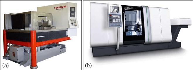
Granite has been widely used in coordinate measurement machines (CMMs).
Likewise, several high precision machine tools include structural parts of this
material; see Fig. 6.15. The main benefit is the reduction of the thermal expansion
coefficient and the accuracy and flatness of the surfaces, but it is obviously a much
more expensive solution than the conventional grey cast iron structure.
In Table 6.2, thermal expansion coefficients of some of the most typical mate-
rials are listed. As explained in Chap. 1, cast iron is the usual solution for conven-
tional machine tools when several aspects are simultaneously evaluated.
In view of the values collected in Table 6.2 and using the above equation, if a
workshop is not properly isolated and the temperature increases 10ºC, for a 1,000
mm
length cast iron component a length variation of more than 0.1 mm is caused.
A general but mistaken belief is that if temperature change is slow enough, ma-
chine and workpieces experiment similar thermal growth. Obviously it is not true
because the machine tool, the fixtures and the workpiece present different thermal
expansion coefficients. Furthermore, if the room temperature changes, the machine,
the fixtures and the workpiece do not change their temperature at the same velocity.
Again it depends on the material thermal conductivity and the size of the elements.
Fig. 6.15 a Ultraprecision centreless grinding machine of Tschudin
®
. b Advanced turning
centre CTX of DMG
®
with granite structural parts
242 A. Lamikiz, L. N. Lopez de Lacalle and A. Celaya
Table 6.2 Thermal expansion coefficients for materials used in machine tool structures and
workpiece materials
Material Coefficient of thermal expansion (α × 10
–6
K
–1
)
Grey cast iron 11.1
Carbon steel (AISI 1045) 10.8
Polymer concrete 11.5–14.0
Granite 08.0–8.5
Aluminium (7075 T6) 23.6
Titanium (Ti6Al4V) 08.6
Stainless steel (AISI 303) 17.3
Although as already mentioned, kinematic design is highly recommended, con-
ventional machine tools are usually high-constrained structures. For this reason,
thermal growths of machine components involve complex structural deformations
since these growths are constrained by other elements. To minimise the effect of
deformation stresses caused by thermal expansion, symmetrical machine structure
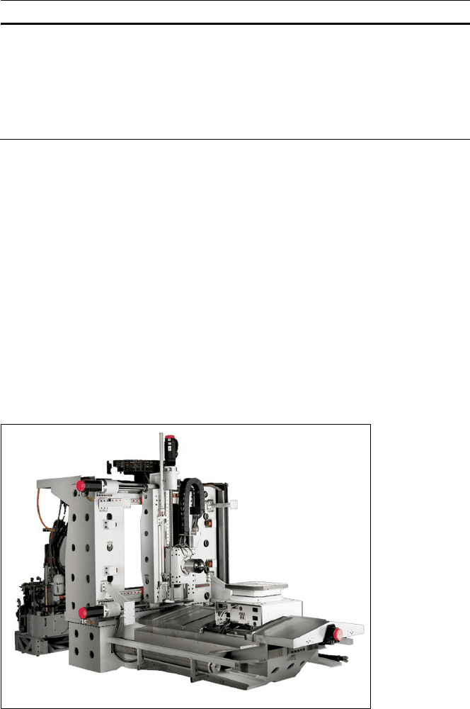
is a good design practice. Thus, the expansion towards one element end is com-
pensated with the expansion to the other side. In Fig. 6.16 a machine tool structure
with a complete symmetrical structure is shown. In this machine, servos and cool-
ing systems are placed away from the working area. This is because these ele-
ments are heat sources which can distort both the machine and the part.
Temperature control of the workshop is necessary through air conditioning sys-
tems, which usually works at 20°C as a reference temperature. As a rule of thumb,
the workshop should be situated in a closed room with heavily insulated walls to
Fig. 6.16 High precision machine tool with symmetrical design, by Dixi
®
