Linden D., Reddy T.B. (eds.) Handbook of batteries
Подождите немного. Документ загружается.

VENTED SINTERED-PLATE NICKEL-CADMIUM BATTERIES 27.7
0.60
0.70
0.80
0.90
1.00
1.10
1.20
1.30
1.40
0.0 10.0 20.0 30.0 40.0 50.0 60.0 70.0 80.0
Time (minutes)
Voltage (V)
1C
2C
3C5C
10C
20C
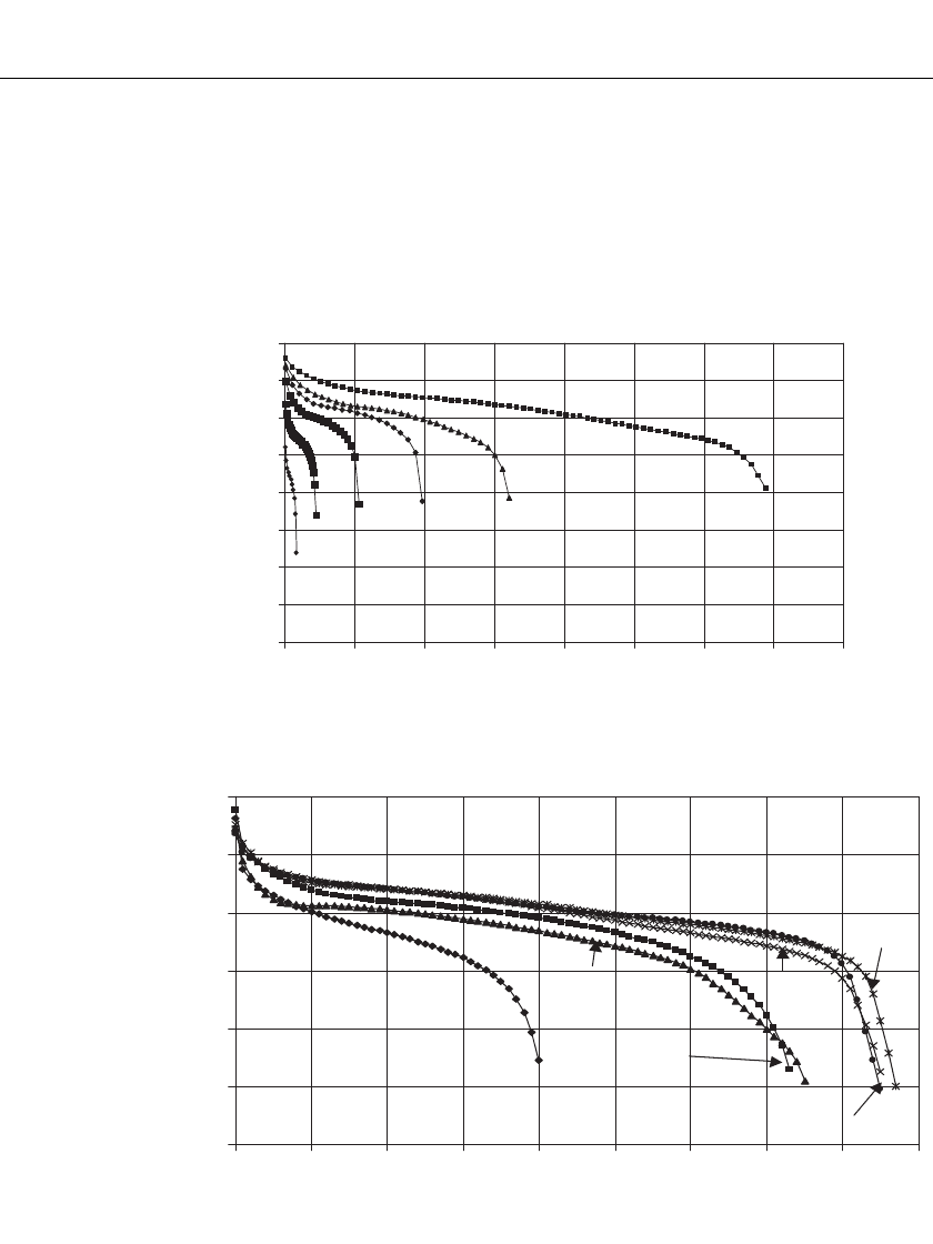
FIGURE 27.3 Typical discharge curves at various C rates, 25⬚C.
16.0
18.0
20.0
22.0
24.0
26.0
28.0
0 102030405060708090
Time (minutes)
Voltage (V)
-40°C-20° C
0 ° C25° C
40° C
70° C
FIGURE 27.4 Typical discharge curves at various temperatures 1C-Rate, 20 cell battery.
27.4 PERFORMANCE CHARACTERISTICS
27.4.1 Discharge Properties
The discharge curves for a typical vented sintered-plate nickel-cadmium battery at various
constant-discharge loads are shown in Fig. 27.3. The discharge curves for a typical battery
at various temperatures are shown in Fig. 27.4. The curves for this battery are characterized
by a flat voltage profile, even at relatively high discharge rates and low temperatures. Voltages
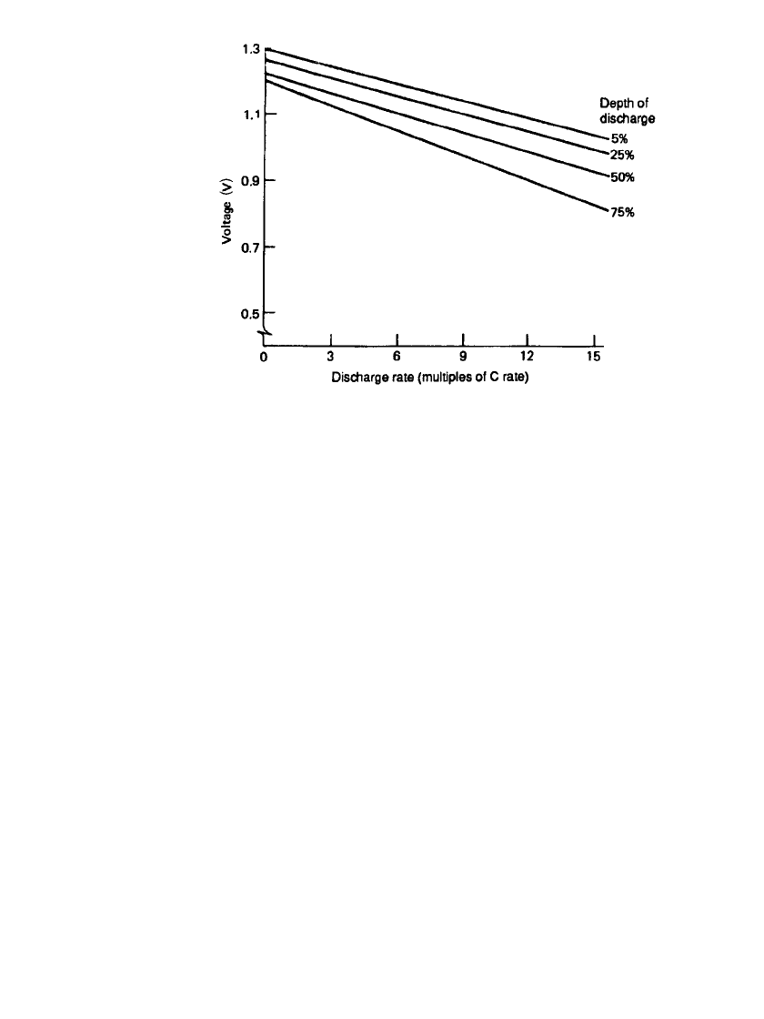
at various constant-current discharge loads and states of discharge are given in Fig. 27.5.
27.8 CHAPTER TWENTY-SEVEN
FIGURE 27.5 Voltage as a function of discharge load and at various
states of charge at 25⬚C.
The battery, because of its low internal resistance, is capable of delivering pulse currents
as high as the 20 to 40C rate. For this reason it can be used successfully for very high power
applications, such as engine starting (see Sec. 27.4.3).
27.4.2 Factors Affecting Capacity
The total capacity that the fully charged sintered-plate vented battery is capable of delivering
is dependent on both discharge rate and temperature, although the sintered-plate battery is
less sensitive to these variables than most other battery systems. The relationships of capacity
to discharge load and temperature are shown in Figs. 27.6 and 27.7, respectively.
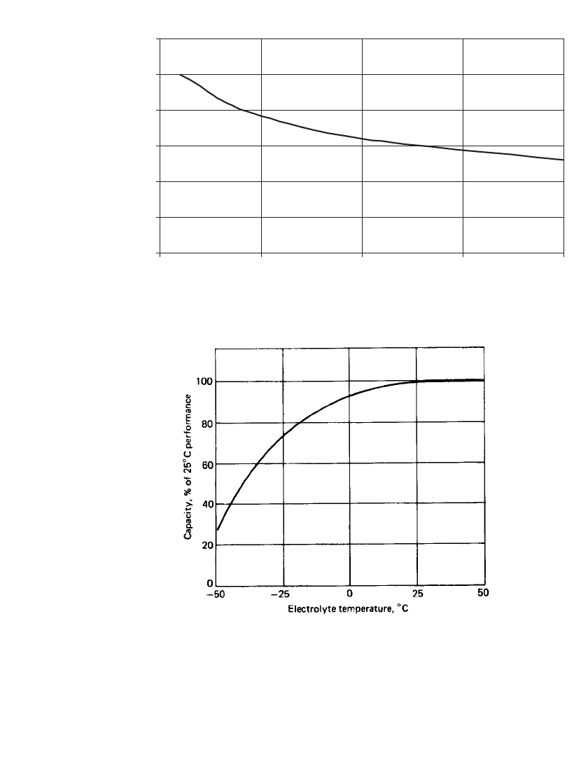
Low-temperature performance is enhanced by the use of eutectic 31% KOH (1.30 specific
gravity) electrolyte which freezes at
⫺66⬚C. Higher or lower concentrations will freeze at
higher temperatures; for example, 26% KOH freezes at
⫺42⬚C. As shown in Fig. 27.7, more
than 60% of the 25
⬚C capacity is available at ⫺35⬚C, with the temperature having an in-
creasingly significant effect as it is reduced toward
⫺50⬚C. At high discharge rates, heat that
is generated may cause the battery to warm up, giving improved performance on immediate
subsequent discharges than would be expected under the ambient conditions.
Vented sintered-plate batteries can also be discharged at elevated temperatures. Strict
control is required, however, when charging at high temperature. As with most chemically
based devices, exposure to high temperatures for extended periods of time will detract from
the life of the battery (see Sec. 27.7.3).
The combined effects of both increased discharge rate and low temperature may be ap-
proximated by multiplying the two derating factors.
VENTED SINTERED-PLATE NICKEL-CADMIUM BATTERIES 27.9
0%
20%
40%
60%
80%
100%
120%
05101520
Discharge Rate (C)
Capacity, % of 1C rate
FIGURE 27.6 Capacity derating as a function of discharge rate at 25⬚C.
FIGURE 27.7 Capacity derating as a function of discharge tem-
perature at 1C rate discharge.
27.4.3 Variable-load Engine-Start Power
The most common and demanding use of the vented sintered-plate nickel-cadmium battery
is as the power source for starting turbine engines on board aircraft. The discharge in this
application occurs at relatively high rates for periods of 15 to 45 s. Typically the load
resistance when the start is initiated, particularly in low-temperature in a marginal-start sit-
uations, is of the same order of magnitude as the effective internal resistance of the battery,
R
e
. The apparent load resistance increases as the engine rotor gradually comes up to speed.
27.10 CHAPTER TWENTY-SEVEN
0
200
400
600
800
1000
1200
1400
0 5 10 15 20 25
Time (s)
Current (Amps)
0
5
10
15
20
25
30
Voltage (v)
current
volta
g
e
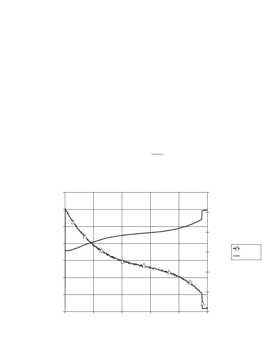
FIGURE 27.8 Battery voltage and current as a function of time for a typical turbine engine start (20 cell
battery).
This results in a typical discharge current which slowly decreases from some high initial
value while the battery voltage recovers from an initial drop of perhaps 50% or more, back
toward 1.2-V per cell, the effective zero load voltage. A representative graph of the battery-
starter voltage and current, expressed as a function of time is shown in Fig. 27.8.
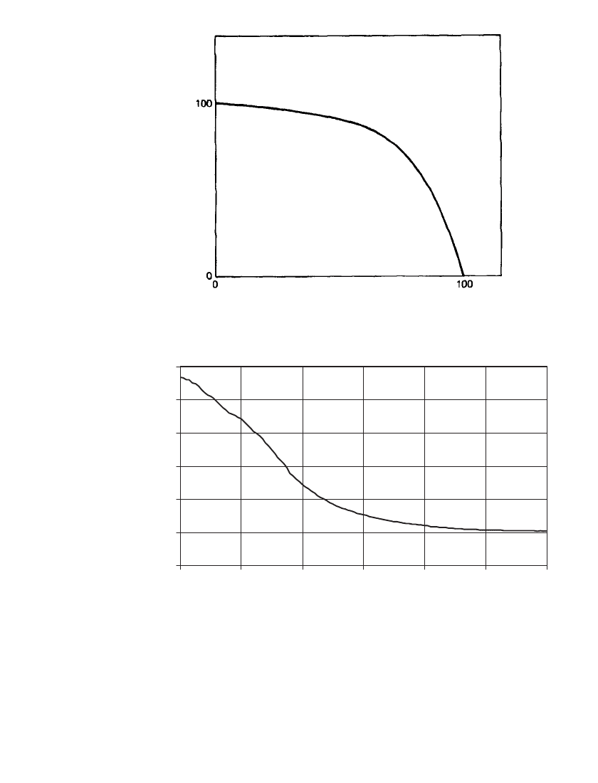
A common and useful measure of battery performance is the maximum power current.
This property is generally defined as the load current at which the battery voltage would be
0.6N V, or one-half of the effective open-circuit voltage (1.2 V/cell) and where N is the
number of cells in the battery. The instantaneous maximum power current decreases with
decreasing state of charge due to rising internal resistance. Its value versus state of charge
tends to behave exponentially, as shown in Fig. 27.9. An approximation of I
mp
may also be
measured by performing a ‘‘constant-potential’’ discharge at 0.6N V for 15 to 120 seconds.
A typical discharge is shown in Fig. 27.10.
The maximum power delivery P
mp
and the effective internal resistance R
e
are related to
the value of I
mp
as follows:
P
⫽ 0.6NI
mp mp
and
0.6N
R ⫽
e
I
mp
VENTED SINTERED-PLATE NICKEL-CADMIUM BATTERIES 27.11
% of discharge
l , % of performance of fully charged battery
mp
FIGURE 27.9 Maximum power current derating as a function of
state of charge at 25⬚C.
0.0
10.0
20.0
30.0
40.0
50.0
60.0
020406080100120
Time (sec)
Current (C Rate)
FIGURE 27.10 Representative 0.6V constant potential discharge at 25⬚C.
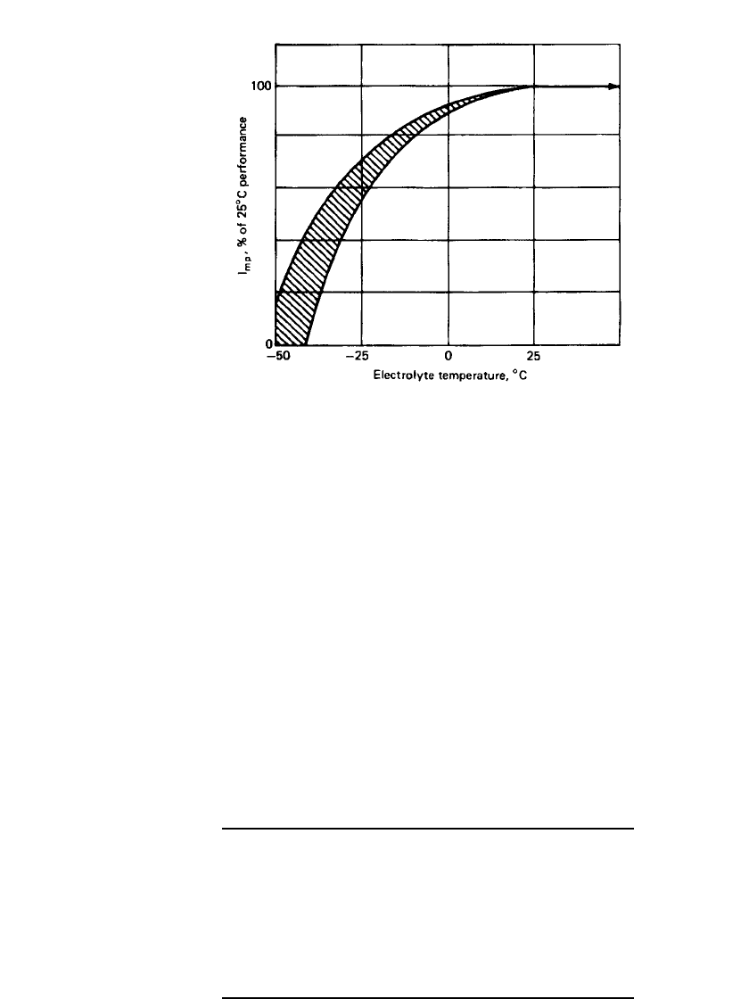
27.4.4 Factors Affecting Maximum Power Current
The value of I
mp
, which a battery is capable of delivering, is maximum at full charge and at
25
⬚C electrolyte temperature. Derating effects due to state-of-charge and electrolyte temper-
ature factors are shown in Figs. 27.9 and 27.11, respectively. It will be noted that both
relationships are nonlinear in that the effects on maximum power delivery, per unit of change,
increase with decreasing state of charge and with decreasing temperature. As with capacity,
the approximate effect of combined low electrolyte temperature and decreased state of charge
27.12 CHAPTER TWENTY-SEVEN
FIGURE 27.11 Maximum power current derating as a function
of battery temperature (fully charged).
may be determined by multiplying the individual factors. It should be noted, however, that
high-rate discharge at low temperature may increase the battery temperature. This self heating
must be accounted for when determining the combined derating factors for a subsequent
discharge. A negligible effect on I
mp
occurs with increases in electrolyte temperature above
25
⬚C.
27.4.5 Energy/Power Density
Typical average values for the energy and power densities of the vented sintered-plate nickel-
cadmium battery at 25⬚C are shown in Table 27.2.
TABLE 27.2 Energy and Power Characteristics of Vented
Sintered-Plate Nickel-Cadmium Battery (Single Cell Basis)
Capacity specific (single cell, C
rate)
25–31 Ah/kg
Capacity density 48–80 Ah /L
Specific energy (C rate) 30–37 Wh / kg
Energy density 58–96 Wh / L
Power specific (at maximum power) 330–460 W / kg
Power density 730–1250 W /L
VENTED SINTERED-PLATE NICKEL-CADMIUM BATTERIES 27.13
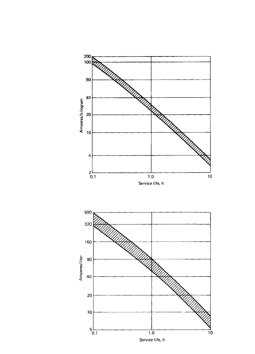
27.4.6 Service Life
The service life (discharge time) of the vented sintered-plate nickel-cadmium cell, normalized
to unit weight (kilogram) and size (liter) at various discharge rates at 25
⬚C, is approximated
in Figs. 27.12 and 27.13.
FIGURE 27.12 Service life of typical vented sintered-plate
nickel-cadmium battery (gravimetric) at 25⬚C.
FIGURE 27.13 Service life of typical vented sintered-plate
nickel-cadmium battery (volumetric) at 25⬚C.
27.14 CHAPTER TWENTY-SEVEN
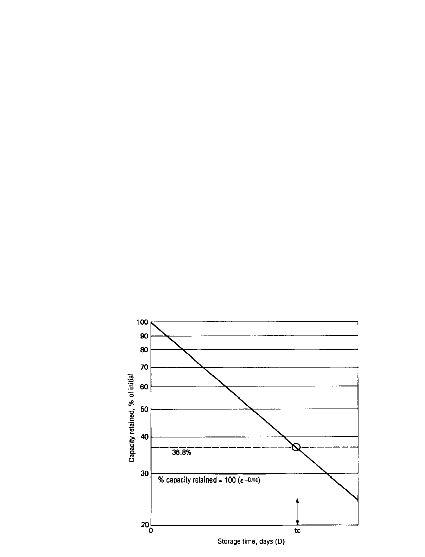
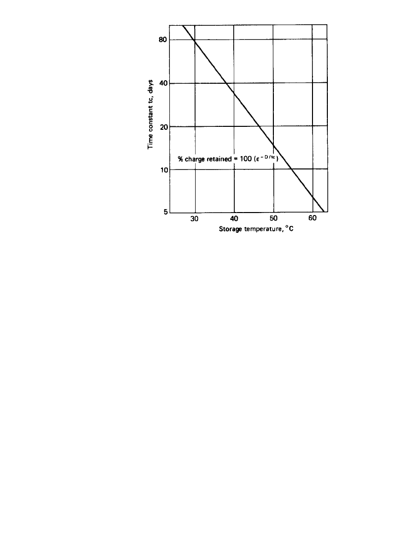
FIGURE 27.14 Capacity retention as a function of storage time.
27.4.7 Charge Retention
Charge retention or capacity retention refers to the amount of dischargeable capacity re-
maining in a battery following prolonged storage under open-circuit conditions. Two mech-
anisms are responsible for the loss of charge, namely, self-discharge and electrical leakage
between cells.
Self-discharge rates are an intrinsic property of cells. Typically, experimental results for
the capacity retained as a function of open-circuit storage time best fit a semilogarithmic
relationship such as that shown in Fig. 27.14. The self-discharge rate of a cell is affected by
impurity levels and the electrochemical stability of the electrodes.
The effect of temperature is shown in Fig. 27.15, where the exponential time constant
(tc), the time to retention of 36.8% of initial capacity, is plotted against temperature. Storage
temperature is the most important factor affecting the self-discharge rate.
The second mechanism, the loss of charge due to electrical leakage, is influenced by the
history of the battery’s use and maintenance. Charge retention usually improves with cycling
of the battery, and this will be true unless this cycling history has been abusive. The main-
tenance factor influencing charge retention is primarily battery cleanliness. Battery charge
can leak from the terminals of one cell to the terminals of other cells across the cell tops if
they are wet with potassium hydroxide. Loss of charge from this cause is relatively unpre-
dictable, but it can usually be prevented by good housekeeping practices. Although surface
leakage may affect only a portion of the cells in the battery, it is important since the capacity
of the battery is limited to that of the lowest-capacity cell. Additionally it unbalances the
cells in the timing of the onset of overcharge voltage response (see Fig. 27.1.).
It should be noted that loss of charge through these mechanisms is not permanent since
the battery capability can be completely restored through comprehensive maintenance prac-
tices and recharging.
VENTED SINTERED-PLATE NICKEL-CADMIUM BATTERIES 27.15
FIGURE 27.15 Charge retention time constant as a
function of storage temperature.
27.4.8 Storage
The sintered-plate cell can be stored in any state of charge and over a very broad temperature
range (
⫺60⬚Cto60⬚C) for an unlimited period. The battery should be clean and dry before
placing it in storage. Intercell hardware may have a light coating of petroleum jelly to prevent
corrosion. It should be fully discharged and shorted prior to storage periods greater than 30
days. Fully discharged batteries that have been stored longer than 30 days should be charged
by a ‘‘slow charge’’ method. The ‘‘slow charge’’ method typically consists of incremental
charge rates to voltage cut-off (i.e. C rate to 1.57 volts, C/2 rate to 1.6 volts), with a final
charge (C/10 or lower) for 2 hours. It is the best practice to store the cells shorted and
upright with proper electrolyte level at a temperature between 0 and 30
⬚C. The preferable
storage method is to allow the battery to discharge through a resistor until the battery voltage
is close to zero. Because a vented Ni-Cd still has considerable power available even at very
low states of charge, failure to completely discharge the battery prior to applying a shorting
device can create a hazardous situation.
27.4.9 Life
The life of the battery is strongly influenced by factors such as the design, the care with
which it is maintained and reconditioned as well as the way it is used; hence it is difficult
to predict battery life. Best life performance is obtained with operation at normal tempera-
tures, temperature-controlled charging, and minimum reconditioning. Some design features
that improve the life expectancy of a battery are: the use of modern separator materials and
gas barriers, the elimination of materials that degrade in KOH (e.g. O-rings), the reduction
of electrolyte impurity levels in manufacturing (by electrolyte flushing and replacement), and
the use of pure nickel components versus nickel-plated steel.
27.16 CHAPTER TWENTY-SEVEN
27.5 CHARGING CHARACTERISTICS
The functional design of the vented cell battery differs from that of the sealed cell battery
primarily by the inclusion of a gas barrier between the positive and negative electrodes. This
gas barrier has one principal function, which is to prevent, as discussed in Sec. 27.3, the
cross-plate migration and recombination of generated gases within the cell. Preventing this
recombination allows both positive and negative plates to return to full charge. This results
in an overvoltage during onset of overcharge, which is used as the feedback signal to control
the charging device. Because the gas is driven out of the cell, however, the vented cell
consumes water, which must be replenished.
Charging of the vented sintered nickel-cadmium battery following its discharge in cyclic
use, has four significant objectives. These may be stated as follows:
1. Restore the charge used during discharge as quickly as possible.
2. Maintain the ‘‘fully charged’’ capacity as high as possible during the use intervals between
removals for maintenance.
3. Minimize the amount of water usage during overcharge.
4. Minimize the damaging effects of overcharge.
Fulfillment of the first objective is the principal reason for the design and use of vented cells,
since the gas barrier provides the ‘‘voltage signal’’ which may be utilized in several different
ways to terminate the fast recharge. The charge may thus be accomplished at the desired
high rate, without compromising the battery, by continuing that rate in overcharge. Objective
2 must inherently be balanced against object 3 and 4 in the design and control of the charging
method. Generally, a continued good capacity between reconditionings is enhanced by pro-
viding more overcharge, while more overcharge inherently utilizes more water and, if suf-
ficiently high, may result in damage to the battery. A compromise must therefore be struck.
Usually about 101 to 105% of the Ampere-hours removed on discharge are replaced on the
subsequent charge.
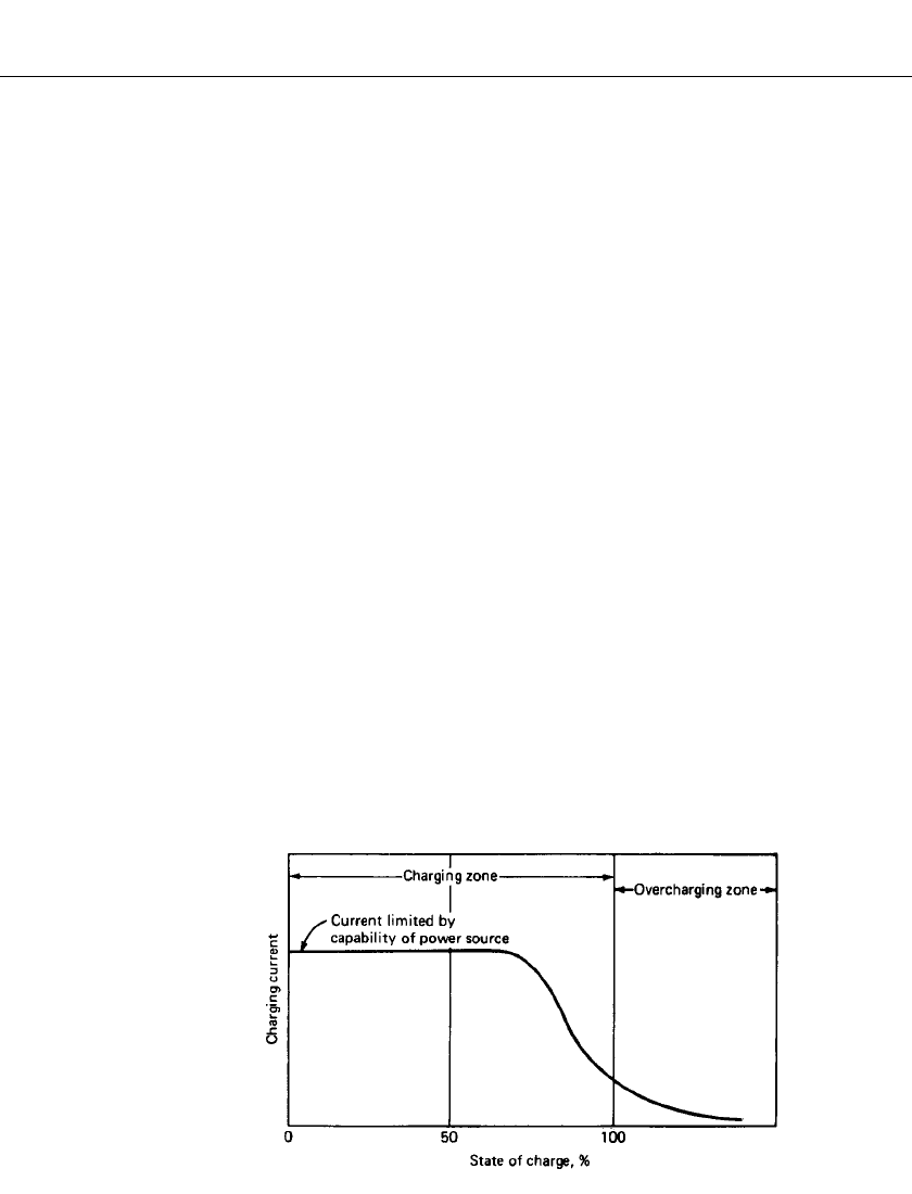
Charging techniques which are used in ‘‘on-board’’ systems utilize the ‘‘signal’’ provided
by the overvoltage of the vented cell in overcharge. This overvoltage signal is shown in Fig.
27.1. This significant voltage rise is present at all charge rates, and its sharpness actually
improves as the cell is cycled in high-rate discharge and recharge. The corollary to this
curve, which shows voltage response at constant current, is the current response at constant
voltage, which may be expected to be somewhat the reverse of Fig. 27.1 and is illustrated
in Fig. 27.16.
FIGURE 27.16 Constant-potential charge current.