Linden D., Reddy T.B. (eds.) Handbook of batteries
Подождите немного. Документ загружается.


VENTED SINTERED-PLATE NICKEL-CADMIUM BATTERIES 27.17
27.5.1 Constant-Potential Recharging
Constant-potential (CP) charging is the oldest of the methods still in use and is typically
utilized in general aviation aircraft. Similar to an automobile battery charging system, CP
charging utilizes a regulated voltage output from the aircraft DC generator, which is me-
chanically coupled to the engine. The voltage is typically regulated at 1.40 to 1.50 V per
cell. Figure 27.16 illustrates the form of the charge current as a function of the state of
charge of the vented cell battery during CP recharging. Although the initial current could be
quite high if limited only by the voltage response of the battery, it most frequently is limited
by the capability of the source as shown. As the battery approaches full charge, however,
the ‘‘back EMF’’ of the battery, illustrated as the charge voltage for the constant-current case
in Fig. 27.1, reduces the current to that required by the battery to provide an overvoltage
equal to the regulated voltage of the charging source. CP charging requires very careful
consideration of the selection of charge voltage and its proper maintenance in order to
achieve the balance between objectives 2 and 3. This is particularly difficult to achieve when
the battery temperature experiences significant variation, since overvoltage is dependent on
battery temperature. This balance may be made essentially independent of battery tempera-
ture effects by means of temperature compensation of the CP voltage, as discussed in Sec.
27.5.4.
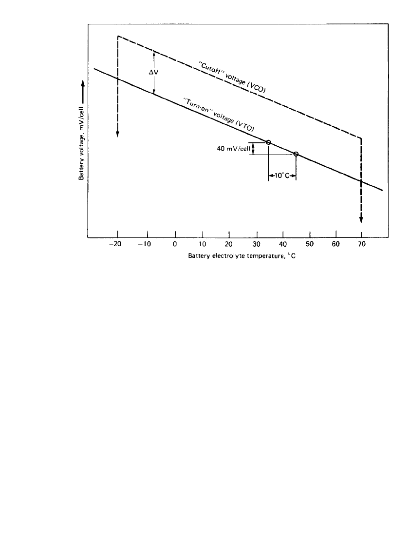
27.5.2 Constant-Current, Voltage-Controlled Recharging
A number of commercially available chargers based in general on constant-current charging
with voltage cutoff control are utilized in modern aircraft. One of the simplest and most
effective of these chargers applies in approximately C-rate constant-current charge to the
battery and then terminates it when the battery voltage reaches a predetermined voltage cutoff
(VCO) value such as 1.50 V per cell. The control also reinitiates the constant-charge current
whenever the open-circuit battery voltage falls to a predetermined lower level, such as 1.36
V per cell. The net result is that the charger will recharge the capacity used during an engine
start, typically 10% of the battery’s total, in approximately 6 min. and then cut the charger
off due to the sharp rise in voltage as the cells go into overcharge, as illustrated in Fig. 27.1.
Shortly thereafter, as the voltage falls below the turn-on voltage, the charge is reinitiated for
a short period of time until the battery voltage again reaches the cutoff voltage. This simple
on-off action continues at decreasing frequency and decreasing lengths of on-time, thereby
maintaining the battery in a float condition at a completely full state-of-charge.
The battery voltage reduction, due to a discharge, inherently initiates the recharging of
the battery without additional controls, thus automatically providing the recharge signal func-
tion regardless of the discharge rate or the reason. Adjustment of the cutoff and turn-on
voltages as a function of battery temperature, which is described in Sec. 27.5.4, matches this
mode of charging to the temperature characteristics of the vented sintered nickel-cadmium
battery, thereby maintaining the desired balance of objectives. Both cutoff and turn-on volt-
ages are compensated at the same rate, thereby maintaining a constant differential between
turn-on and cutoff. A diagram of the function of this simple basic charge control scheme is
shown in Fig. 27.17.
Several other proprietary chargers, based in part on the simple techniques outlined here,
may also be found in commercial use. Many of these chargers also provide auxiliary func-
tions such as upper and lower battery temperature charge discontinuation, detection of mal-
functioning cells in the battery by detecting half-battery voltage imbalance, and signaling
the user in the event of either of these conditions.
27.18 CHAPTER TWENTY-SEVEN
FIGURE 27.17 Charger control voltages as a function of battery temperature, C-rate charge
(nominal values).
27.5.3 Other Charging Methods
The charging methods outlined in the preceding are those used in order to achieve fast
recharging of a battery which has been discharged in normal use. Periodic maintenance of
the vented sintered-plated nickel-cadmium battery, however, requires a full and complete
discharge of each cell followed by a thorough recharge well into overcharge. This places
both positive and negative plates in each cell of the battery in full and complete overcharge.
The battery may then be returned to service with all plates of all cells in the same full
charged condition, thus enabling the battery to work from the ‘‘top down.’’
The simplest maintenance charge method, requiring the least complex equipment to en-
sure this fully balanced, fully overcharged condition, is the low-rate charge. This technique
utilizes a constant-current, approximately C/ 10 charge-overcharge current without voltage
feedback control. At this low rate the charge may be continued safely into overcharge without
compromising the physical integrity of the components of the cell. This charge current should
be maintained until at least twice the rated capacity of the battery has been replaced. Since
this will inherently result in water usage, water level replenishment is best performed on a
fully charged battery just prior to placing the battery back into service at the conclusion of
this maintenance charging routine.
Batteries in standby service can be maintained in a fully charged condition by a float or
trickle charge similar to pocket plate batteries. The float voltage for vented sintered-plate
batteries is 1.36 to 1.38 V per cell.
VENTED SINTERED-PLATE NICKEL-CADMIUM BATTERIES 27.19
27.5.4 Temperature Compensation of Charge Voltage
In both the constant-potential and the constant-current VCO charging methods, it has been
pointed out that the selection of voltage is a compromise between the minimization of water
usage and the maintenance of a high state of charge. The inherent change of overcharge
voltage as a function of battery temperature increases the difficulty of this compromise
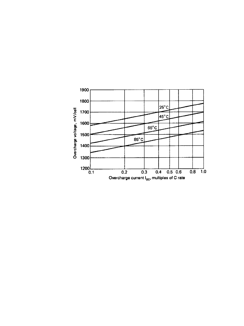
significantly. This voltage effect is shown as the Tafel curves in Fig. 27.18. The relationship
between the Tafel curves at various temperatures indicates a temperature coefficient of
⫺4
mV/
⬚C at constant-current conditions. In other words, overcharge voltage, at constant cur-
rent, decreases by approximately 4 mV per cell for each 1
⬚C rise in cell temperature.
FIGURE 27.18 Overcharge voltage as a function of current and tem-
perature (Tafel curves).
As shown by the slope of these Tafel curves, overcharge voltage is also a linear function
of the logarithm of overcharge current. That slope for vented sintered-plate nickel-cadmium
batteries is approximately 200 mV per cell per decade of change in overcharge current. Thus
with constant-potential charging without temperature compensation, the overcharge current,
and therefore both water usage and the overcharge damaging effects, will increase approx-
imately 60% for each 10
⬚C increase in electrolyte temperature.
A convenient technique for avoiding the detrimental effects of an increasing electrolyte
temperature is to compensate the ‘‘constant’’-potential voltage, or the constant-current cutoff/
turn-on voltages, for this change in battery temperature at the rate of
⫺4mV/⬚C per cell.
This may be accurately accomplished through the use of thermistors or other temperature-
sensitive electric devices installed in the battery case to signal cell temperature. It is important
that cell temperature and not ambient temperature be sensed by this device. There may be
significant differences between the two. This function for the constant-current charging sys-
tem is also shown in Fig. 27.17. The selection and use of the proper value of temperature
compensation permits the battery charging system to function as though the battery were
maintained at a constant temperature. Care must be exercised in the design and manufacture
of these devices, since they must operate in an environment of potassium hydroxide which
is electrically conductive and also has a propensity to wet and creep on most surfaces. High-
grade potting processes must therefore be used to insulate and protect all auxiliary electronic
components and wiring placed inside the battery case.

27.20 CHAPTER TWENTY-SEVEN
27.6 MAINTENANCE PROCEDURES
27.6.1 Electrical Reconditioning
The periodic maintenance of the vented sintered-plate nickel-cadmium battery has six specific
objectives:
1. Assess the timeliness of the preselected maintenance period schedule.
2. Restore the electrical performance, both capacity and power.
3. Detect and isolate cell failures and facilitate their replacement.
4. Physically clean the battery.
5. Replenish the water in the electrolyte.
6. Maintain the charging-system voltage calibration.
A relatively simple electrical procedure fulfills the first objective, namely a single discharge,
initially at a relatively high rate to simulate engine start and second at a relatively low rate,
approximating that of the 1-h value. This split-rate discharge of the battery as removed from
the aircraft serves as a measure of its performance readiness while it was in the aircraft. The
15-s high-rate portion, at approximately the I
mp
rate of discharge, while measuring the voltage
with the capacity removed, determines the relative engine start power capability. The capacity
removed during the low-rate portion of the discharge at approximately the C rate, when
added to the Ampere-hour capacity removed during the high rate test, determines the status
of the available emergency energy capacity. The battery, prior to performing this discharge
should be in the same ‘‘fully’’ charged condition that would typically be encountered when,
it is in the normal installation. Comparison of this power delivery, and the total available
capacity as removed from the aircraft, with the requirements of the application will allow
the user to determine whether the maintenance schedule interval may be increased or whether
it needs to be decreased.
The restoration of the electrical characteristics of the battery, known as electrical recon-
ditioning or deep cycle maintenance, objective 2, may be accomplished in two additional
simple steps. The first is a thorough and complete discharge of each cell in the battery in
order to discharge all the active material. The second step is the complete recharge of each
plate of each cell into full gassing overcharge. The first step consists of a C rate discharge
to approximately 0.7 volts. Once all cells have reached voltage, then resistors short cells to
0.010 volts per cell or 16 hours, whichever occurs first. The second step is accomplished by
charging the battery with constant current at a value of one-tenth its Ampere-hour rating
(C/ 10) for at least 20 h. Since the capacity for some of the cells in the battery may be as
much as 30 to 40% greater than the rated value, the total charge of 2.0C Ah is sufficient to
ensure that both plates of all cells reach the full overcharge required. Adjust electrolyte levels
accordingly. The battery should have deep cycle maintenance performed every 1000 flight
hours or 500 starts, whichever occurs first or when any abnormal operation of the battery is
observed.
There are other procedures used, and recommended by the manufacturers of specialized
proprietary equipment, to recondition cells in a shorter period of time. Periodic maintenance
in a qualified service center is necessary for optimum performance of the battery. The efficacy
of each should be verified and the added expense and complexity entailed in the use of these
proprietary reconditioning devices justified in specific applications. Care must always be
exercised in their use, however, to avoid sustained high-rate overcharge, which may damage
the gas barrier material.

VENTED SINTERED-PLATE NICKEL-CADMIUM BATTERIES 27.21
Evaluation of cell-to-battery case leakage current, part of objective 3, when the battery
is first received for maintenance will determine the electrical need for cell cleanup as well
as the presence of cracked or leaking cell cases. This procedure may be conveniently carried
out by the simple expedient of completing a circuit from each cell terminal to the battery
case with a fused ammeter. A significant amount of leakage current through the ammeter to
the case from anywhere in the cell electric circuit indicates the presence of a conductive
path, through potassium hydroxide, on the external surfaces of the cell cases. Such a con-
ductive path may result from spewing of the electrolyte during overcharge, which may in-
dicate either overfilling or the existence of a cracked or leaky cell case. Isolation of the exact
cause can be accomplished by determining the leakage ‘‘nodal’’ point in the cell string by
repeating the measurements after physical cleanup of the battery.
Detection of the failure of the gas barrier, a very important part of objective 3, may be
reliably and conveniently accomplished by extending the C /10 charge to 24 h. This over-
charge will indicate accurately the failure of the gas barrier by either or both of two principal
measurements near the end of that overcharge. First, the overcharge gassing rate is extremely
sensitive to gas barrier condition and gas recombination. When measured with a simple ball
flowmeter, the 24-h gas rate will be less than 80% of normal if the barrier has failed sig-
nificantly in the cell. The normal value is 11 ml /min for each ampere of the C /10 overcharge
rate. The second indicator of gas barrier failure will be a 24-h overcharge voltage of less
than 1.5 V if the cell is being charged in a 23
⬚C ambient. Some downward adjustment of
this voltage criterion may be made at the rate of 4 m V/
⬚C if the battery is being charged
in a higher ambient temperature.
27.6.2 Mechanical Maintenance
The replenishment of water in the electrolyte to return the electrolyte to the level recom-
mended, objective 5, is the most important routine mechanical procedure employed during
battery reconditioning. It is best accomplished near the end of the 24 hours of the C/ 10 rate
charge by replenishing with deionized water until the electrolyte reaches the recommended
level for a battery in overcharge. A record of the amount of water usage in each cell should
be maintained and compared with the battery manufacturer’s statement of reserve electrolyte
level in each cell. If the total water usage between maintenance fillings, after deducting the
amount used during the maintenance procedure, exceeds the reserve available in that cell
design, the maintenance interval must be shortened to prevent plate dry-out during use and
resultant cell failure. Note that the 24-h C/10 reconditioning procedure will itself use ap-
proximately 0.4 ml of water for each Ampere-hour of rated capacity during the 24-h recon-
ditioning period. For example, 12 mL of water would be used during the reconditioning
period for a 30-Ah rated cell, and this must be subtracted from the amount added to deter-
mine the amount actually used in service. It should also be noted that a cell with a damaged
gas barrier may use less water.
That point in the maintenance procedure, following the thorough short-circuiting of each
cell, may be utilized to perform physical maintenance. Cells may only be replaced while in
the discharged state. Cleanup generally consists of a thorough rinsing with clear water fol-
lowed by warm-air drying of the battery. This will dissolve and remove any accumulation
of potassium hydroxide and carbonates from the outside of the cell jars. Vent caps should
also be washed in warm de-ionized water, warm water forced through the vent, and then
dried with warm air. This is safely accomplished only with the cells in the completely
discharged state. Replacement of any cells not found defective until the conclusion of the
C/ 10 overcharge requires discharging the cells a second time.
Other typical hardware problems include, loose terminal nuts—indicated by burns or
arcing on intercell links; terminal seal failure—various heavy deposits around cell terminal,
remove all hardware and the O-ring; vent failure—various heavy deposits on or around the
vent valve, the valve may have been installed improperly or the vent sleeve or O-ring has

27.22 CHAPTER TWENTY-SEVEN
failed; also inspect the vent sleeve to insure it is not torn or broken. Power delivery of the
battery may be enhanced by removing intercell link hardware, buffing contact surfaces, then
replacing and retorquing all connectors.
27.6.3 System Inspection Criteria
Reinstallation of the reconditioned and fully charged battery into the aircraft system presents
the opportunity for performing the system voltage calibration check in fulfillment of objective
6. The only measurement required for this on a CP charging system is to record the value
of the battery voltage, after reactivating the system and following stabilization of the voltage.
This stable value is the regulated float voltage to which the battery will be subjected during
extended overcharge in use. This voltage measurement should be made at the battery with
the engine running at a sufficiently high speed to produce a representative and stable value.
The battery voltage measurement, on constant-current VCO systems, should be made just
as the system reaches cutoff voltage. The regulated voltage, on either of the two systems,
should then be adjusted to the manufacturer’s recommended value if necessary. These ad-
justments must consider the effects of any automatic temperature compensation of voltage
present in the system.
27.7 RELIABILITY
27.7.1 Failure Modes
The sintered plate construction is very robust and capable of operating in both high and low
temperature extremes. The cell is capable of withstanding substantial abuse and still per-
forming as intended. It can be discharged into reversal and given a substantial amount of
overcharge, as long as the temperature is controlled. The gas barrier that prevents recombi-
nation of the oxygen on the cadmium electrode aids control of the temperature during charge.
In the past, cellophane was mainly used as the gas barrier. It had a tendency to hydrolyze
in the electrolyte and eventually decompose to carbonate and derivatives of the cellophane
structure. In recent times, the cellophane has been replaced with Celgard
威 3400 or other
similar materials.
10
These materials are polyethylene and polypropylene based, and do not
degrade in the 30% KOH electrolyte. Should the cell’s gas barrier fail, continuing in oper-
ation for enough cycles will result in the battery losing capacity and maximum power ca-
pability. Continued temperature increase in the cell can result in fusing, or melting, of the
nylon separator and result in an internal short circuit of the cell.
Although the cellophane replacement used for the gas barrier alleviates the above failure
mechanism, it introduces another problem, if the cell is not manufactured and maintained
properly. Without proper additives in the electrolyte, which find their way into the cadmium
electrode during cycling, the cell can lose capacity in the negative electrode. The role of
supplying an oxidized cellophane expander for the cadmium electrode needs to be replaced
by cellulose derivatives and other additives to maintain the negative capacity.
11
Several other failure modes which account for a small portion of cell and battery failures
include the following: (1) Internally short-circuited cells can result from cut-through of the
electrical separator by burrs and other plate irregularities, aggravated by cell interplate pres-
sures and vibration. (2) Cracked and leaking cell cases may result from abusive handling of
the cells during cell replacement procedures and maintenance, or from defective manufac-
turing or sealing procedures. (3) Burned terminal contacts may result from faulty cleaning
and buffing procedures during maintenance, insufficient link assembly torquing, terminal
screw failure, or conductive articles being dropped on the internal connectors of a charged
battery.

VENTED SINTERED-PLATE NICKEL-CADMIUM BATTERIES 27.23
27.7.2 Memory Effect
In addition to these permanent failures, there is a reversible effect which may result in a
gradual reduction of both power and capacity with cycling. This effect, sometimes referred
to as ‘‘memory effect,’’ ‘‘fading,’’ or ‘‘voltage depression,’’ results from charging following
repetitive shallow discharges where some portion of the active materials in the cell is not
used or discharged, such as in a typical engine-start use. This effect is noticed when the
previously undischarged material is eventually discharged. The terminal voltage during the
latter part of that full discharge may be lower by approximately 120 mV (hence, ‘‘voltage
depression’’). The total capacity is not reduced, however, if the discharge is continued to the
lower voltages, as, for example, to the ‘‘knee’’ of the curve.
This effect is completely reversible by a maintenance cycle consisting of a thorough
discharge followed by a full and complete charge-overcharge as described in Sec. 27.6.1.
27.7.3 Factors Influencing Gas Barrier Failure
Gas barrier failure is generally acknowledged to be caused or aggravated by excessive over-
charge current, excessive overcharge temperatures, and discharge at high rates with low
electrolyte levels. Gas barrier failure may not be detectable during reconditioning with other
than the low-rate constant-current procedures. Barrier failures may actually occur during
poorly structured maintenance and then manifest themselves at a later time after reinstallation
in the aircraft. This possibility emphasizes the importance of an accurate assessment of the
condition of the gas barrier at the end of the reconditioning period just prior to reinstallation.
This assessment is accurately made by the measurement of overcharge gas flow following
the extended C/10 overcharge, as described in Sec. 27.6.1.
One indication of the significant importance of the two factors of (1) temperature com-
pensation of charger voltage and (2) effective maintenance practices is the existence of large-
scale field data which document real-time failure differences of up to 100:1. These life
differences exist between well-maintained batteries in temperature-compensated systems on
the one hand and identical battery designs in uncompensated CP systems with frequent and
poorly managed maintenance procedures on the other. Recent improvements in gas barrier
materials have significantly reduced these failures.
27.7.4 Thermal Runaway
The loss of the gas barrier in one or more cells of a vented nickel-cadmium battery can lead
to thermal runaway. Loss of this function allows oxygen, generated in overcharge, to reach
the negative plate and recombine on it. This generates heat. The temperature increase which
follows causes the internal cell voltage to decrease. Charge current then increases exponen-
tially to increase cell voltage to match the charger voltage.
Thermal runaway occurs with the use of a voltage-regulated (CP) charge source on a
battery containing cells with a failed gas barrier. Thermal runaway begins when the failed
cells approach overcharge following recharge. The (over)charge current may reach a mini-
mum and then gradually increase. Voltage inequities may exist at this point unless all cells
are experiencing similar recombination (gas barrier damage). Oxygen recombination heats,
and begins to increase the temperature of the failed cell or cells and thus their neighboring
cells unless the battery is effectively air cooled. The resulting temperature increase, however,
proceeds slowly due to the large thermal mass involved. It may take 2 to 4 hours of (near)
consecutive overcharging for a cell to reach boiling temperature.

27.24 CHAPTER TWENTY-SEVEN
If the boiling phase continues long enough, or is repeated, and the failed cell becomes
dry, large inequities in cell voltage will appear. The voltage across the cell that has boiled
dry will increase, thereby decreasing the charge current and the voltage across the cells that
are still wet with electrolyte. The next event probably will be internal short-circuiting of the
dried-out cell due to very high temperatures and voltage at the last remaining damp spots
with consequent burning of the electrical separator insulation. The (over)charge current then
increases sharply due to cell loss, and the process repeats itself with the next cell to go dry.
Because of extensive heating and boil away times, thermal runaway may go undetected
for many flight hours following the onset of gas barrier failure if the use of the system is
not consecutive or continuous. This can confuse the perceived connection between the cause
of the gas barrier damage and the resultant thermal runaway.
27.7.5 Potential Hazards
Potential hazards which may be present during the use and maintenance of the vented sin-
tered nickel-cadmium battery fall into five general categories, as described in this section.
Gas Fire and /or Explosion. Since all functional vented batteries generate a stoichiometric
mixture of hydrogen and oxygen gases during overcharge and expel them normally from the
cell into the battery container, a potential for explosion of these gases is always present.
Two conditions are necessary for such an explosion, however, and both are recognized and
accounted for in the design of a typical system. The first condition is the accumulation of a
sufficient quantity of this gas mixture. This condition is minimized in all system designs by
the incorporation of adequate battery case ventilation. Some designs rely on supplying a
modest quantity of air to purging tubes on the battery from overboard vents in the aircraft.
Others incorporate natural convection of the gases from a louvered battery case into a ven-
tilated compartment. Air-cooled designs inherently accomplish the required ventilation due
to the large volume of air used.
Unusual circumstances, however, may defeat any of these gas-purging techniques. It
should also be remembered that batteries generate a significant amount of explosive gas
during the maintenance procedure, and therefore maintenance should always be performed
in a well-ventilated shop.
The second condition necessary for explosion of the gases is the presence of a source of
ignition. Although normally there are no ignition sources inside the battery case, several
abnormal possibilities do exist. One is the internal short-circuiting of a relatively dry cell in
overcharge, resulting in an explosion inside the cell with a subsequent ejection of flames
into the battery case. A second and more likely source of ignition may exist at an improperly
maintained cell terminal due to the high temperatures generated during high-rate discharge.
A third source of ignition may occur at the site of stray leakage currents.
Although the coincidence of both a sufficient amount of gas accumulation and a source
of ignition is quite rare, it can and has happened. Because of this possibility, many batteries
are also designed to be physically capable of managing a hydrogen or oxygen explosion and
containing the effects entirely within the battery case. Typically these batteries will also be
electrically functional for at least one C-rate discharge following such an explosion.
Arcing and Burning. This potential hazard concerns excessive leakage currents through
electrolyte paths outside the cells. Such currents can occur either between cells which are
physically adjacent but with a wide voltage separation in the cell circuit or, more probably,
from a cell to a grounded metallic case. Arcing is more likely to occur, however, in the
circuit of an inappropriately protected auxiliary device located inside the battery case in the
environment containing potassium hydroxide. Some examples of these devices are battery
heaters, thermal detectors, and voltage sensors. The proper design of these auxiliary appli-
ances must recognize the conductivity of KOH and the ability of that electrolyte to creep

VENTED SINTERED-PLATE NICKEL-CADMIUM BATTERIES 27.25
along wires and even into mechanically ‘‘sealed’’ insulation. Devices of this type should be
tested with high dielectric voltages while submerged in a water-detergent mix before they
are installed in the battery case environment.
The result of a sustained leakage current through relatively localized KOH conducting
paths may be the ignition of the explosive environment by arcing, as discussed previously.
The result might also be the carbonization of adjacent insulating materials and the subsequent
burning of those materials within the battery case.
Electrical Power. One of the essential functional capabilities required of the vented nickel-
cadmium battery is the ability to deliver high-power rates for engine starting. This very
capability, however, presents a potential risk in the form of hot spots on improperly torqued
cell terminals during high-rate discharge. It is also a potential hazard to the unwary main-
tenance technician operating with metallic tools or other objects, such as jewelry, in a careless
manner in the vicinity of charged batteries. Since the short-circuit current of these cells
(batteries) may exceed 1000 to 4000 A, it should be obvious that the exposed conductors of
a charged battery should be treated with respectful caution. Very severe burns may occur if,
for example, a ring should accidentally make contact between two adjacent cell terminals.
Although one of the most obvious, this hazard is one of the most frequently encountered.
Insulated cell hardware does provide a partial solution: however, caution and respect for the
available power must always be exercised.
Corrosive KOH. Because of the corrosive nature of the KOH used as an electrolyte, all
material employed in the construction of the battery and its accessory appliances must be
KOH immune. Materials such as nylon, polypropylene, nickel-plated steel, steel, and stainless
steel are therefore used. The potential hazard of KOH corrosiveness, however, is primarily
encountered during maintenance. The use of safety glasses and safety face shields should be
mandatory while performing maintenance on these batteries. A very small amount of KOH
in the eye, for example, without prompt, continued, and adequate flushing followed by med-
ical treatment can result in the loss of eyesight. KOH is also corrosive to the skin, and the
affected area should be thoroughly washed and rinsed with water, thereby minimizing the
detrimental effect.
Electric Shock. Most vented sintered nickel-cadmium batteries are arrayed in groups of 10
to 30 cells, presenting maximum voltages of 15 to 45 V. There are applications, however;
in which batteries are connected electrically in series strings of 90 to 200 cells or more. It
should be apparent that the voltages presented by this number of cells in series may be lethal
to anyone exposed to them. Personnel should also be cautioned, because of the high prob-
ability of electrolyte being present between the cell circuit and the conductive external sur-
face of the battery, to exercise care by disconnecting series-connected batteries prior to
personal exposure. Significant shock currents may be carried by relatively small amounts of
KOH.

27.26 CHAPTER TWENTY-SEVEN
27.8 CELL AND BATTERY DESIGNS
27.8.1 Typical Vented Sintered-Plate Nickel-Cadmium Cells
A listing of several typical vented sintered-plate nickel-cadmium cells is given in Table 27.3.
The 14-, 22-, and 36-Ah sizes are those typically employed in aircraft batteries. Other cells
are available in sizes up to about 350 Ah. The larger cells are generally constructed in steel
containers rather than the plastic containers now used for the aircraft-size cells.
TABLE 27.3 Typical Vented Sintered Plate Nickel-Cadmium Cell Properties
Rated capacity
(A-h) Cell designation Height (cm) Width (cm) Thickness (cm) Weight (grams)
1.5
2
5.5
5.5
7
6
13
10
12
20
28
23
36
40
42
100
2B02-0
2A02-0
5A06-0
5C06-1
0707-0
0906-1
1313-1
1410-1
1412-0
2020-1
2028-1
2223-1
3030-1
4040-1
4240-1
6060-1
10.16
8.74
10.31
10.36
18.85
11.60
11.93
14.48
14.38
17.42
17.27
20.57
17.42
23.31
23.31
24.48
2.92
3.81
5.51
5.51
6.65
5.89
7.95
5.89
5.86
7.95
7.95
8.08
7.95
7.95
7.95
12.7
1.70
1.83
2.39
2.39
1.29
2.69
3.02
2.69
2.69
3.53
3.53
2.72
5.08
3.53
3.53
3.83
86
95
236
272
299
354
486
445
422
1067
1149
903
1562
1453
1453
2860
Source: Courtesy of Eagle-Picker Technologies, LLC. Power Systems Dept.
27.8.2 Typical Battery Designs
A typical arrangement of vented sintered nickel-cadmium cells into a battery configuration
is the conventional aircraft battery. An example of this use is shown in Fig. 27.19 and in
detail in Fig. 27.20. This arrangement generally consists of a completely enclosing battery
case and cover made of either stainless steel or steel with a KOH-resistant finish of epoxy
or paint. The cover is typically secured with over-center-type latches. The battery case is
provided with gas-purging vents or with freely convective gas-diffusion openings for dilution.
The cells are encased in nylon-molded cell cases with terminals extending through a nylon
cover sealed to the case. The cells are electrically connected in series with nickel-plated
copper links from cell terminal to cell terminal and from the first and last cell to the battery
termination and disconnect device. This battery termination extends through the battery case
wall and is present on the outside surface of the battery case as a recessed double-male,
polarized, high-current receptacle. Functional requirements of aircraft batteries are specified
in SAE standard AS 8033A.