Linden D., Reddy T.B. (eds.) Handbook of batteries
Подождите немного. Документ загружается.

LITHIUM BATTERIES 14.35
19.0
17.0
15.0
13.0
11.0
9.0
7.0
5.0
3.0
1
10 100
25°C
55°C
72°C
0°C
–30°C
mA
DRAIN RATE (mA)
CAPACITY (Ah)
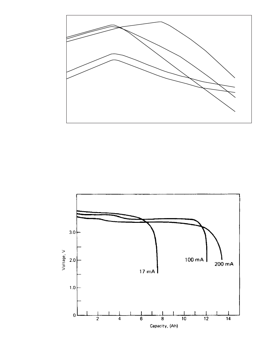
FIGURE 14.18 Performance characteristics of high-capacity cylindrical bobbin D-size batteries as a
function of drain rate at various temperatures. (Ref. 23.)
FIGURE 14.19 Discharge characteristics of Li / SOCl
2
cylindrical D-size bobbin bat-
tery at 145⬚C. (From Ref. 24.)
14.36 CHAPTER FOURTEEN
1 10 100 1000 10000 100000
Hours
Volts
40
3.5
3.0
2.5
2.0
1.5
1.0
169 Ω
20 mA
(1.65 Ah)
1.74 K Ω
2 mA
(2.40 Ah)
11.8 K Ω
300 µA
(2.30 Ah)
39.2 K Ω
90 µA
(2.20 Ah)
147 K Ω
25 µA
(2.00 Ah)
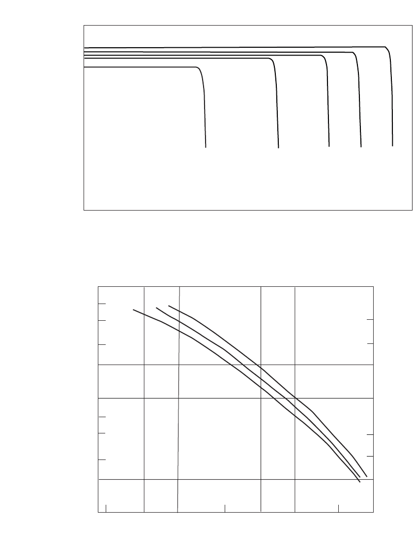
FIGURE 14.20 Discharge characteristics of high-capacity Li / SOCl
2
cylindrical AA-size bobbin battery on
low-rate discharge at ⫹25⬚C. (Ref. 23.)
Hours of Service
Amperes/kilogram
1.0
0.7
0.5
0.3
0.2
0.1
0.07
0.05
0.03
0.02
0.01
50 100 200 500 1000 2000 5000 10,000
1.770
0.885
0.531
0.354
0.177
0.088
0.053
0.0177
Amperes/liter
25 C
0 C
-30 C
o
o
o
0.035
FIGURE 14.21 Service life of Li / SOCl
2
cylindrical high-capacity bobbin batteries to 2.0 volt cut-off.
LITHIUM BATTERIES 14.37
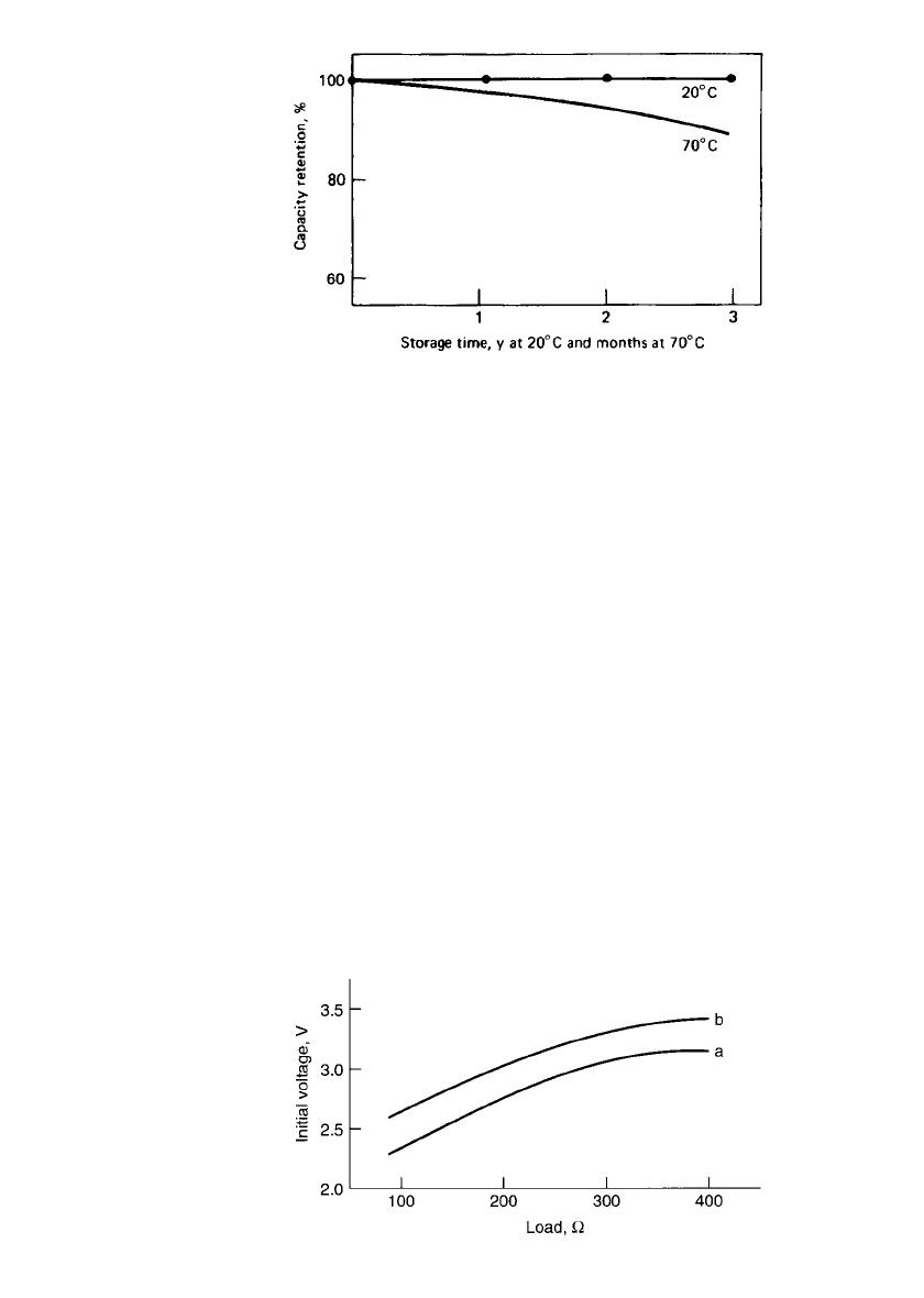
FIGURE 14.22 Capacity retention of Li / SOCl
2
cylindrical bob-
bin battery (From Ref. 23.)
FIGURE 14.23 Li / SOCl
2
cylindrical AA-size bobbin batter-
ies—minimum voltage vs. load after 2-year storage at 25⬚C; (a)
standard construction; (b) with loading on lithium anode.
After storage, the Li /SOCl
2
, battery may exhibit a delay in reaching its operating voltage
because of the formation of the LiCl film on the lithium surface. The voltage delay becomes
more pronounced with a heavier discharge load and lower discharge temperature. The voltage
delay of the Li /SOCl
2
cells can be improved by an in situ coating of the lithium anode with
an ionic conductor-solid-electrolyte interface. The improvement is shown in Fig. 14.23 which
compares the minimum voltage and the load after 2 years of storage for both the standard
construction and the coated one. It shows the dependence of the closed-circuit voltage on
the discharge current of AA cells after 2 years of storage at 25
⬚C. Once the discharge is
started, the passivation film is dissipated gradually, the internal resistance returns to its normal
value, and the plateau voltage is reached. The passivation film may be removed more rapidly
by the application of high-current pulses for a short period or, alternatively, by short-
circuiting the batteries momentarily several times until the cell is activated. The use of a
pulse provides more reproducible results.
Special Characteristics. The bobbin batteries are designed to limit the possibility of haz-
ardous operation and to eliminate the need (in some designs) for a safety vent. This is
achieved by minimizing the reactive surface area and increasing the heat dissipation, thus
limiting the short-circuit current and a hazardous temperature rise, respectively. These cells
also are cathode-limited, a feature that was found safer than anode-limited cells for this
design.
25
The batteries have withstood short circuits, forced discharge, and charging under
certain conditions with no hazardous condition.
23,24,26
Batteries should not be disposed of in
fire or subjected to long-term exposure at temperatures near 180
⬚C because they may explode.
14.38 CHAPTER FOURTEEN
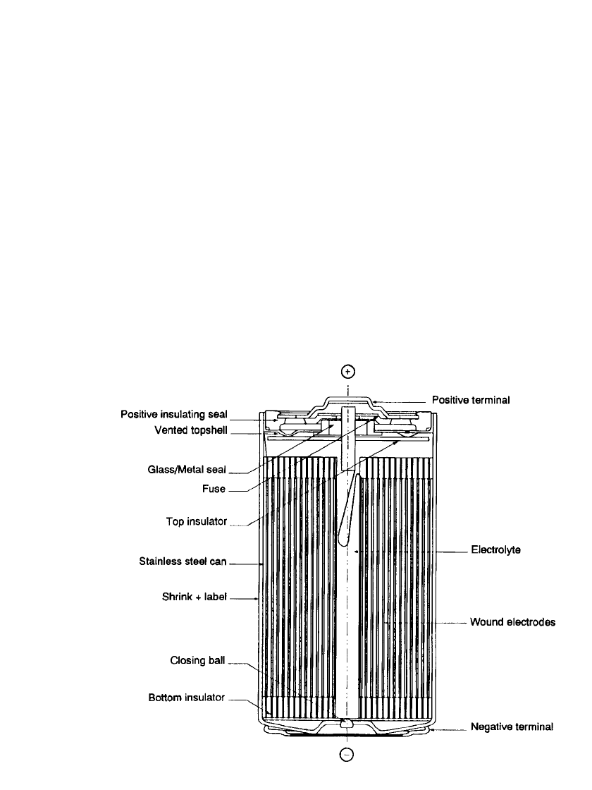
FIGURE 14.24 Cutaway view of lithium/ thionyl chloride spirally wound electrode battery.
(Courtesy of SAFT America, Inc.)
Battery Sizes. The bobbin-type Li/SOCl
2
batteries are manufactured in the standard ANSI
cell sizes as well as in special cell and battery configurations. Although some of these
batteries may be physically interchangeable with conventional zinc batteries, they are not
electrically interchangeable because of their higher voltages.
Table 14.11 lists the properties of some of the typical bobbin-type batteries that are
manufactured. These characteristics may vary with the manufacturer. Manufacturer’s data
should be consulted for specific data as well as for the characteristics of their other batteries.
14.6.3 Spirally Wound Cylindrical Batteries
Medium to moderately high-power Li/SOCl
2
batteries which are designed within spirally
wound electrode structure are also available. These batteries were developed primarily to
meet military specifications where high drains and low-temperature operation were required.
They are now also used in selected industrial applications where these features are also
needed.
A typical construction is shown in Fig. 14.24. The cell container is made of stainless
steel, a corrosion-resistant glass-to-metal feed-through is used for the positive terminal, and
the cell cover is laser sealed or welded to provide an hermetic closure. Safety devices, such
as a vent and a fuse or a PTC device, are incorporated in the cell to protect against buildup
of internal pressure or external short circuits.
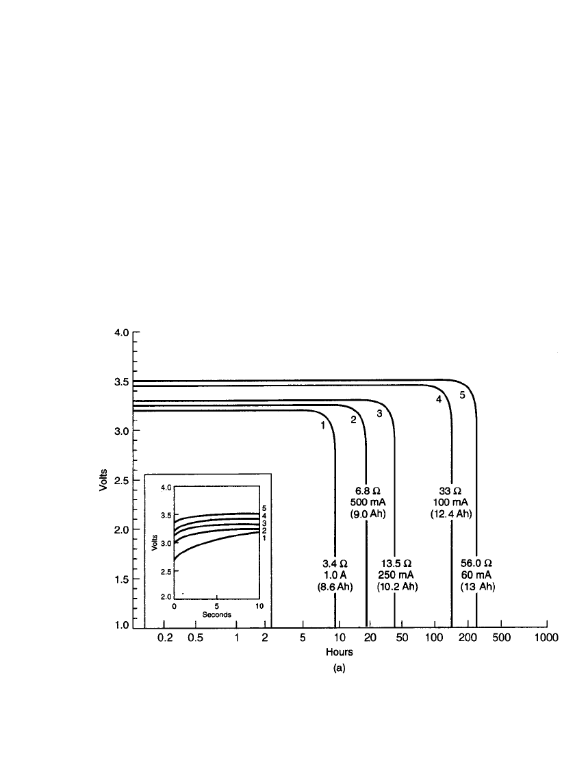
LITHIUM BATTERIES 14.39
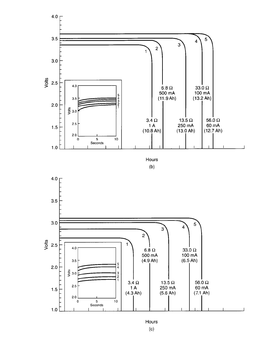
The discharge curves for a D-size battery are plotted in Fig. 14.25, showing the higher
performance at the moderate drains compared to the bobbin cell (see Fig. 14.17). The inserts
in Fig. 14.25 show the voltage response when the load is initially applied. The voltage of
these cells recovers within 10 s as they incorporate an anode-coating technology, as discussed
earlier.
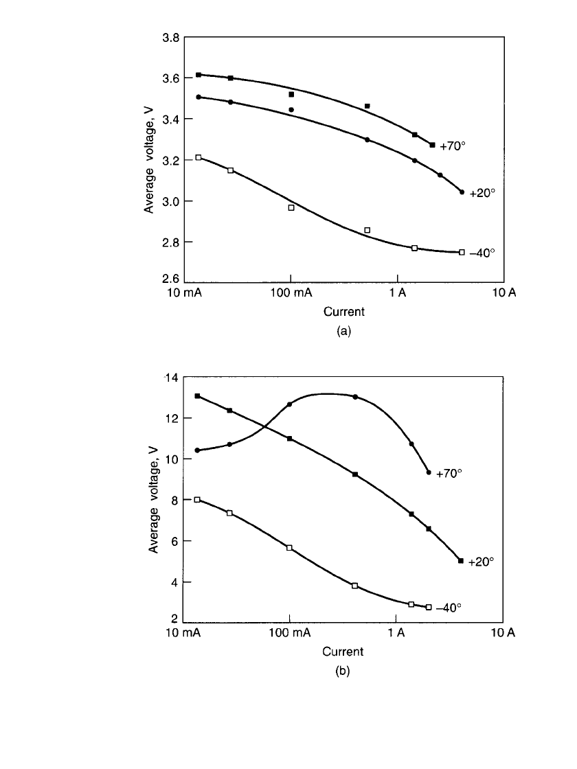
Figure 14.26 summarizes the performance characteristics of the D-size battery, showing
the relationship of voltage and capacity with current drain at several temperatures.
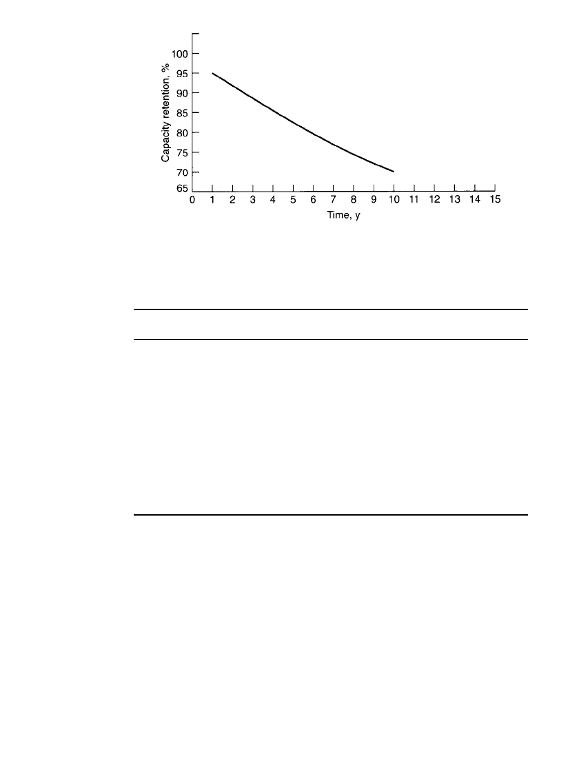
The capacity retention after storage at 20
⬚C is shown in Fig. 14.27. Like the other Li/
SOCl
2
batteries, these batteries have an excellent storage capability over a wide temperature
range due to the buildup of a protective lithium chloride layer on the lithium. This passivation
layer, however, may cause a voltage delay under some discharge conditions. Table 14.12
lists the characteristics of typical cylindrical spirally wound Li/ SOCl
2
batteries.
FIGURE 14.25 Discharge characteristics of spirally wound Li / SOCl
2
D-size battery, medium dis-
charge rate at (a)25⬚C. (Courtesy of SAFT America, Inc.)
14.40 CHAPTER FOURTEEN
0.2
0.5
1 2
510
20
50
100 200
500
1000
0.2
0.5 1
2 51020 50 100 200 500 1000
2010
FIGURE 14.25 Discharge characteristics of spirally wound Li / SOCl
2
D-size battery, medium dis-
charge rate at (b)72⬚C, (c) ⫺40⬚C. (Courtesy of SAFT America, Inc.)(Continued ).
LITHIUM BATTERIES 14.41
FIGURE 14.26 Discharge characteristics of spirally wound Li / SOCl
2
D-size bat-
tery, medium rate. (a) Voltage vs. current. (b) Capacity vs. current. (Courtesy of
SAFT America, Inc.)
14.42 CHAPTER FOURTEEN
FIGURE 14.27 Capacity retention of spirally wound Li / SOCl
2
D-size
cell, storage at 20⬚C. (Courtesy of SAFT America, Inc.)
TABLE 14.12 Characteristics of Typical Cylindrical Spirally Wound Li / SOCl
2
Batteries
1
⁄3CC D
Rated capacity at 20⬚C, Ah 1.15 5.5 13.0
Dimensions (max)
Diameter, mm 26.2 26.0 33.1
Height, mm 18.9 49.9 61.4
Volume, cm
3
10.2 26.5 52.8
Weight, g 24 51 100
Maximum current for continuous use, mA 400 800 1800
Specific energy/ Energy density
Wh/ kg 168 377 455
Wh/ L 395 726 860
Recommended operating temperature range,
⬚C ⫺60 to 85
Source: SAFT America, Inc.
14.6.4 Flat or Disk-Type Li /SOCl
2
Cells
The Li /SOCl
2
system was also designed in a flat or disk-shaped cell configuration with a
moderate to high discharge rate capability. These batteries are hermetically sealed and in-
corporate a number of features to safely handle abusive conditions, such as short circuit,
reversal, and overheating, within design limits.
The battery shown in Fig. 14.28 consists of a single or multiple assembly of disk-shaped
lithium anodes, separators, and carbon cathodes sealed in a stainless-steel case containing a
ceramic feed-through for the anode and insulation between the positive and negative termin-
als of the cell.
26
LITHIUM BATTERIES 14.43
TABLE 14.13 Characteristics of Disk-Type Li / SOCl
2
Batteries
Capacity,
Ah
Diameter,
mm
Height,
mm
Weight,
g
Maximum
continuous
current, A
Specific
energy
Wh/kg
Energy
density
Wh/L
500 432 127 7,270 7 240 915
1400 432 35 1,600 16 350 930
2000 432 51 17,700 25 385 910
8000 432 187 56,800 40 475 990
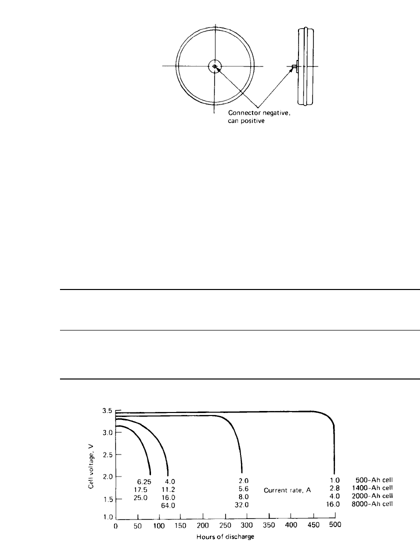
FIGURE 14.29 Performance characteristics of disk-type Li / SOCl
2
cells. High-capacity cell;
typical performance at 0–25⬚C range to 2.5 V cut-off.
FIGURE 14.28 Disk-type Li/ SOCl
2
cell.
The batteries have been manufactured in small and large diameter sizes. Originally de-
veloped by Altus Corp., they are currently being produced in large sizes only for U.S. Navy
applications by HED Battery Corp., Santa Clara, CA. The characteristics of these batteries
are summarized in Table 14.13. Discharge curves for large batteries are shown in Fig. 14.29.
Typically the cells have a high energy density, flat discharge profiles, and the capability of
performance over the temperature range of
⫺40 to 70⬚C. On storage they can retain 90% of
the capacity after storage of 5 years at 20
⬚C, or 6 months at 45⬚C or of 1 month at 70⬚C.

14.44 CHAPTER FOURTEEN
TABLE 14.14 Performance Characteristics of 1000 Ah
LMRS Lithium / Thionyl Chloride Cells and Batteries
(Number of Cells Tested Indicated in Parenthesis After
Each Test)
Configuration Rate Ah kWh Wh / kg
Single (1) C/ 22–C/ 67 931 3.12 108
Single (5) C/ 25–C/ 67 913 3.00 105
Single (2) C/ 40 927 3.09 111
4-cell C/ 25–C/ 50 1053 3.58 125
4-cell C/ 40 1075 3.67 126
4-cell C/ 60 1004 3.41 119
12-cell C/ 20–C/ 40 896 3.03 106
12-cell C/ 20–C/ 40 1016 3.44 121
The cell design includes the following features:
1. Short-circuit protection: Structure of interconnects fuses at high currents, providing an
open circuit.
2. Reverse-voltage chemical switch: Upon cell reversal, it allows cell to endure 100% ca-
pacity reversal, up to 10-h rate, without venting or pressure increase.
3. Antipassivation ( precoat lithium anode): Reduces voltage delay by retarding growth of
LiCl film; large cells stored for 2 years reach operating voltage within 20 s.
4. Self-venting: Ceramic seal is designed to vent cell at predetermined pressures.
27
These cells are used as multicell batteries in naval applications.
Recent work on these designs
28,29
has involved 1000 and 1200 Amp-hour cells for appli-
cation in a U.S. Navy Long-Range Mine Reconnaissance System (LMRS). These are scaled-
down versions of 2350 Ah cells which had shown the ability to operate at the C /40 rate,
providing a power density of 2.3 W/ kg. Both 1000 and 1200 Ah cells were 20.3 cm in
diameter with an annular cavity in the center of the disk. The former unit was 9.53 cm high,
while the latter was 12.07 cm high. Both designs incorporate a ceramic-to-metal seal capable
of carrying 60 amps and both were limited by the capacity of the carbon cathode with Li /
SOCl
2
capacity ratio balanced. The 1000 Ah units were tested individually and as 4 and 12-
cell batteries with 0.5 cm intercell insulators and compressed between 1.59 cm aluminum
end-plates by tie-rods. The 12-cell battery consisted of three stacks of four cells with a
diameter of 45.3 cm designed to fit within the hull of LRMS. Test data is summarized in
Table 14.14. Based on the results of this testing, a 30-cell battery weighing about 205 kg
would deliver 100 kWh at 100 Volts for operational power up to 5kW. Subsequently, the
cell capacity was increased to 1200 Ah by increasing the cell height.
29
These cells were
subjected to a series of safety tests as defined by NAVSEA INST 9310.1B (June 13, 1992)
and U.S. Navy Technical Manual S9310-AQ-SAF-010. The 1200 Ah units were subjected
to intermittent and sustained short circuits, forced discharge into voltage reversal, charging
tolerance and high-temperature discharge and high-temperature exposure after low temper-
ature (0
⬚C) discharge. No cells produced venting, loss of material or case breach of any kind
during these tests, nor were there indications of internal shorts or potentially violent condi-
tions. The pulsed and sustained soft-shorts produced significant heating and pressure, but
these were within the capability of the battery to operate safely. At sustained currents in
excess of 110 Amps, the cathode appears to clog rapidly, limiting capacity. The exothermic
response obtained when the battery was quickly heated to 75
⬚C after cold discharge at 40
Amps at 0
⬚C is a result of accelerated anode repassivation. The subsequent 55⬚C short-circuit
