Linden D., Reddy T.B. (eds.) Handbook of batteries
Подождите немного. Документ загружается.

40.8 CHAPTER FORTY
(a) (b)
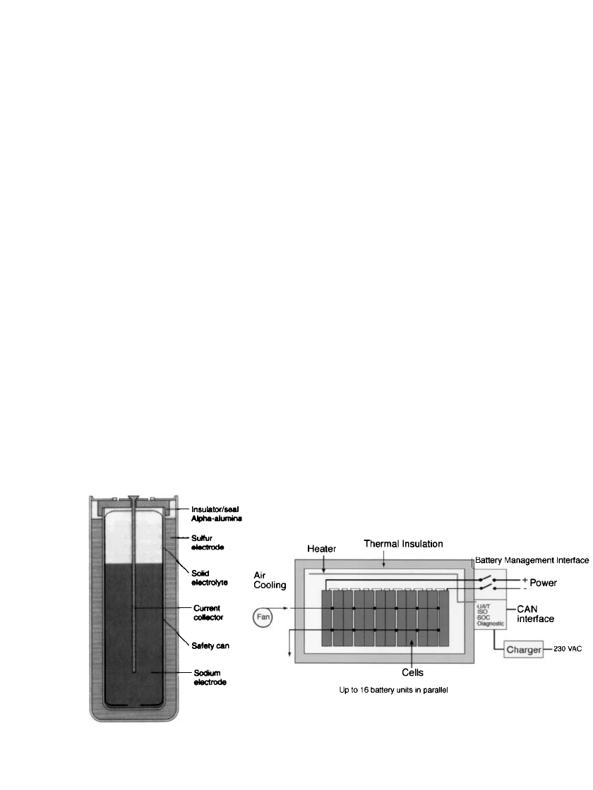
FIGURE 40.5 Schematic diagrams of reference sodium-beta cell and battery configurations: (a) monopolar
sodium / sulfur cell (SPL XPB cell), and (b) a sodium / nickel-chloride battery (Diagram (b) is courtesy of
MES-DEA SA).
Major Components. A simplified schematic diagram of a standard monopolar cell design
is shown in Fig. 40.5a. Referring to this figure, every cell contains the following components:
Electrolyte: A solid

ⴖ-Al
2
O
3
ceramic functions as the electrolyte by conducting sodium
ions (ionic charge transfer) between the positive and negative electrodes. At operating
temperature, the conductivity of the

ⴖ-Al
2
O
3
is approximately equivalent to that for the
electrolytes used in most aqueous batteries. In addition, this component is impermeable
to the molten reactants and has negligible electronic conductivity. Thus, the electrolyte
also functions as an excellent separator for the molten electrodes, preventing any direct
self-discharge and permitting 100% coulombic efficiency. In all modern cell designs, the
electrolyte is formed in the shape of a closed-end tube.
Negative (sodium) electrode: This component contains the sodium metal that is electro-
chemically oxidized during discharge and an inert conductive metal component for trans-
ferring current to a terminal (current collector). In Fig. 40.5a the current collector is a
combination of the metal rod and the metal container. The sodium is placed on the inside
of the electrolyte tube. This cell configuration is preferred by all developers and is termed
central sodium. The internal metal container restricts the flow of sodium to the electrolyte,
thus effectively limiting the quantity of sodium that can be exposed to sulfur in the event
of seal or electrolyte failure to the volume in the very small container-electrolyte gap.
Positive (sulfur) electrode: The constituents of this elecrode include the sulfur that is
reduced during discharge and a current collector. In Fig. 40.5a, the current collector
consists of the external metal container and a layer of compressed carbon or graphite felt
within the space between the electrolyte and the container (not shown). The carbon fibers
are needed to conduct electrons through the insulating sulfur.
External metal container: This component facilitates packaging and safe handling and,
as noted, functions as a current collector. In a central sodium cell, the external container
must resist corrosive attack by molten sodium polysulfides (discharge reaction product).
The best corrosion-resistant materials identified to date use aluminum or chromium or
one of their alloys. Usually chromium-containing layers are coated on an inexpensive
substrate.

SODIUM-BETA BATTERIES 40.9
Seals: To prevent exposure of cell reactants to the external atmosphere, hermetic seals
are required. Their physical design and materials of construction are important because
of the high operating temperature and the presence of internal corrosive liquids. Two
types of seals are needed: one to join the

ⴖ-Al
2
O
3
electrolyte to an insulating
␣
-Al
2
O
3
component; and the other to join the metal current collectors to the same
␣
-Al
2
O
3
. The
two ceramic components are normally sealed with a glass that is stable in sodium, sulfur,
and sodium polysulfides and has a similar coefficient of thermal expansion to the ceramic
components. The metal-to-ceramic seals typically use some form of mechanical or ther-
mocompression bonding.
Physical Configuration
Electrolyte Shape. The cell design with a single-electrolyte tube is preferred from the
perspective of the electrolyte primarily because of manufacturing and service-life consider-
ations. Attempts to manufacture flat-plate electrolyte shapes with satisfactory quality have
been unsuccessful. Significant problems have also been encountered with the seals around
the perimeter of the plates because of thermal expansion mismatch and poor chemical du-
rability. Finally, the capability of flat-plate cells to accommodate freeze-thaw cycles and
vibration has not been validated. As is discussed in Sec. 40.3.3, sodium /nickel-chloride cells
now use a single electrolyte tube with a cruciform/fluted cross-section shape to improve cell
power. Multitube approaches have also been proposed as a technique to achieving high power
levels, and experimental assemblies have been constructed. However, the problems that have
precluded serious consideration of the multitube configuration include difficulty in fabricating
the complex alpha-alumina headers, sharing of positive-electrode reactants, overfilling of
some tubes during recharge, and an inability to prevent self-discharge of the cell after an
electrolyte failure.
Aspect Ratio. Several factors influence the practical limits of the aspect ratio (length to
diameter) of a cell, including electrolyte manufacturability, cell power-to-energy ratio, and
cell durability. From the perspective of cost and energy density, cells with a large capacity
are advantageous. However, the following considerations relative to each of these factors
force a compromise solution to be sought.
•
Longer electrolyte lengths are more difficult to manufacture with acceptable minimum
thickness, diameter tolerances, and manufacturing yield. In the next subsection, NGK In-
sulators Ltd. has recently had remarkable success reliably fabricating very long electrolyte
tubes.
•
If length and thickness are maintained, as the electrolyte (and cell) diameter decreases,
power density increases. However, a practical limit exists because electrolyte manufactur-
ing yields, gravimetric energy density, and cell cost per unit energy deteriorate. Cell length
does not, in general, affect energy density or power significantly, but longer cells cost less
per unit of energy. Most cell lengths are limited by an application-related space constraint,
by manufacturing yield considerations, or by the inability to keep the resistance of the
current collectors low.
•
In standard tubular cell designs, increasing the aspect ratio may have important negative
implications on the ability of the cell to survive thermal cycling and vibration or shock.
These detrimental effects occur because of higher mechanical stresses on the seals and the
electrolyte-header interface as the length of the electrolyte increases. Also, non-uniform
conditions associated with longer cells can produce reduced safety performance and greater
thermal gradients.

40.10 CHAPTER FORTY
Positive/Negative Electrode Location. In the tubular cell design, either sodium or sulfur
can be contained within the electrolyte, and the corresponding configurations are referred to
as central sodium and central sulfur, respectively. Each configuration has advantages and
disadvantages. For example, in the normally preferred central-sodium approach, the cost of
a corrosion-resistant cell container is a significant portion of the total material costs. A central
sulfur design would reduce the required quantity of corrosion-resistant material substantially
and thus provide potential savings. The major disadvantages of the central sulfur design are
its questionable ability to survive freeze-thaw cycling and its lower power (due to a limited
area for conduction). Central sodium and central sulfur cells also possess different thermal
characteristics because of the relative thermal conductivities of sodium and sulfur. In the
central sulfur design, the sodium between the electrolyte and the container provides good
heat conduction, whereas in the central sodium design the sulfur acts as an insulating blanket.
Cell Orientation. Cells can theoretically be designed for operation in a horizontal or a
vertical orientation, although success has only been attained with vertical cells. The advan-
tage of horizontal orientation is greatly improved battery-packaging flexibility. For example,
the limited height of electric-vehicle batteries eliminates the potential to use long vertical
cells. In addition, with a horizontal operation the electrical path length between cells would
be minimized, reducing battery resistance and weight. Unfortunately, reactants segregate in
horizontal cells due to gravity, producing reduced freeze-thaw durability and increased sen-
sitivity to vibration and shock. This, coupled with poor sodium distribution, eliminated hor-
izontal cells from serious consideration.
Component Thickness
Electrolyte. The electrolyte contributes a significant portion to the total cell resistance,
a factor directly related to its wall thickness and area. A thinner electrolyte tube reduces cell
resistance, although a penalty on manufacturing yields and mechanical durability is usually
incurred.
Electrodes. The structure and thickness of the positive electrode can have a substantial
effect on cell resistance, polarization (effect of charge and discharge rate), and recharge
characteristics. Increasing thickness degrades all three of these performance parameters. The
relationship between positive electrode thickness and performance requires accurate model-
ing to ensure that the correct projections of performance are made when changing cell
dimensions. The thickness of the negative electrode compartment is not an electrical factor
because it is filled with highly conductive sodium metal.
Container. The cost and weight of the cell container are related to its wall thickness.
Cost is influenced mainly by the fabrication method and the cell aspect ratio. Typically,
containers with an aspect ratio of less than 4 can be pressed from relatively thin material.
Construction Materials
Positive Electrode. Two different electrode structures have been developed for construct-
ing sulfur electrodes that have good recharge characteristics. The purpose of both methods
is to reduce the amount of elemental sulfur that forms on the electrolyte surface during
recharge. One method uses physical components that are preferentially wet by sodium pol-
ysulfides and the other alters the electric-potential distribution in the sulfur electrode by
using graded-porosity carbon or graphite felt. In general, the first method produces cells with
better recharge characteristics, but because the cells have a more complicated structure, this
method can be more costly. The primary advantages of the graded felt approach are lower
cost and better lower-temperature operation.
Container. A major materials challenge associated with central sodium cells is the iden-
tification of a suitable sulfur container. The solution to this problem is difficult because the
container must be very corrosion-resistant, have a surface with reasonable electrical conduc-
tivity, possess good mechanical properties, and yet be lightweight and inexpensive. Corrosion
is detrimental not only because of its direct impact on the cell lifetime, but also because
SODIUM-BETA BATTERIES 40.11
corrosion products can cause the electrical performance of the cell to continuously degrade.
A container constructed with a single material has proven impractical because the two known
corrosion-resistant, electrically conductive metals (molybdenum and chromium) are generally
too expensive or difficult to fabricate. In addition, molybdenum sometimes produces irre-
versible cell polarization problems, a phenomenon that still is not fully understood. Alumi-
num has excellent durability in the presence of corrosive sodium polysulfides, but forms a
nonconducting sulfide product layer. Although a few nickel-based superalloys and stainless
steels have fair resistance to molten sodium polysulfides, their corrosion rate is too high for
the long life desired for these cells (more than five years). Thus with unacceptable single-
component containers, manufacturers have been forced to select and use composite materials.
These are usually an inexpensive substrate (such as aluminum, carbon steel, or stainless
steel) that has been coated, plated, or sheathed with at least one corrosion-resistant material.
The key to success of these composites is to ensure that the corrosion-resistant layer is defect
free, thus preventing undermining, substrate attack, and spalling.
40.3.2 Sodium/Sulfur Cell Technology
General. The majority of the work on the sodium/sulfur technology has been directed to
electric-vehicle and stationary energy-storage applications. Cells intended for aerospace and
defense-related applications (e.g., satellites, submarines, and tanks) have primarily been
based on electric-vehicle designs. As noted in Sec. 40.1, the only active development of this
technology is currently being performed in Japan for stationary applications and a photograph
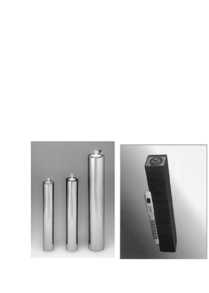
of three of NGK’s cells is shown in Fig. 40.6a. The electrical performance characteristics
(a) (b)
FIGURE 40.6 Modern sodium-beta battery cells: (a) 3 NGK sodium / sulfur cells (left to right—T4.1, T4.2,
T5.1), and (b) an MES-DEA sodium / nickel-chloride cell (ML3). For reference, the dimensions of the largest
NGK cell are 91 mm in diameter ⫻ 515 mm long while the MES ML3 cell is 36 mm square ⫻ 232 mm
long. ( Photographs courtesy of Tokyo Electric Power Company and NGK Insulators, Ltd. (a) and MES-DEA
SA (b)).
40.12 CHAPTER FORTY
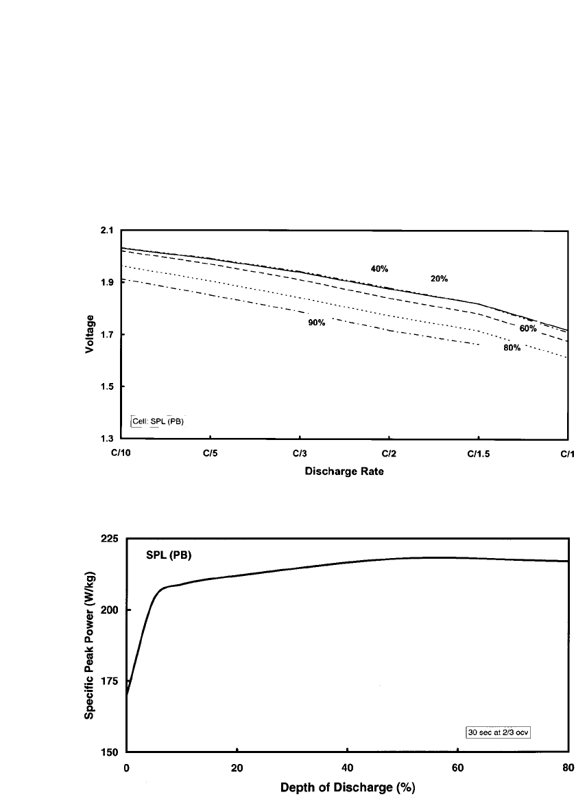
FIGURE 40.7 Cell voltage as a function of discharge rate for an SPL PB sodium /sulfur cell. The parameter
is depth of discharge.
FIGURE 40.8 Specific peak power as a function of depth of discharge for an SPL PB sodium / sulfur cell.
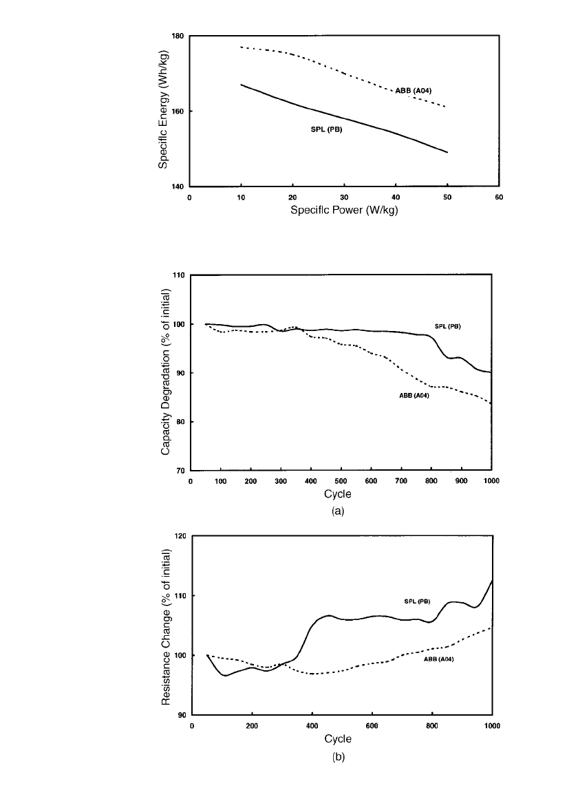
of this technology are demonstrated in the graphs presented in Figs. 40.7 to 40.11. These
figures are based on data collected at Sandia National Laboratories for two of the advanced
electric-vehicle cell designs developed by ABB and SPL respectively. The relative insensi-
tivity of the cell voltage-current behavior and the peak power to the depth of discharge
(‘‘stiffness’’) is demonstrated in Figs. 40.7 and 40.8. A Ragone plot (relation of specific
power to specific energy) is shown in Fig. 40.9. When considering the Ragone plot, it is
important to remember that these data are only for cells (does not include weight burdens
associated with battery hardware). Typically, cells constitute 50 to 60% of the battery weight.
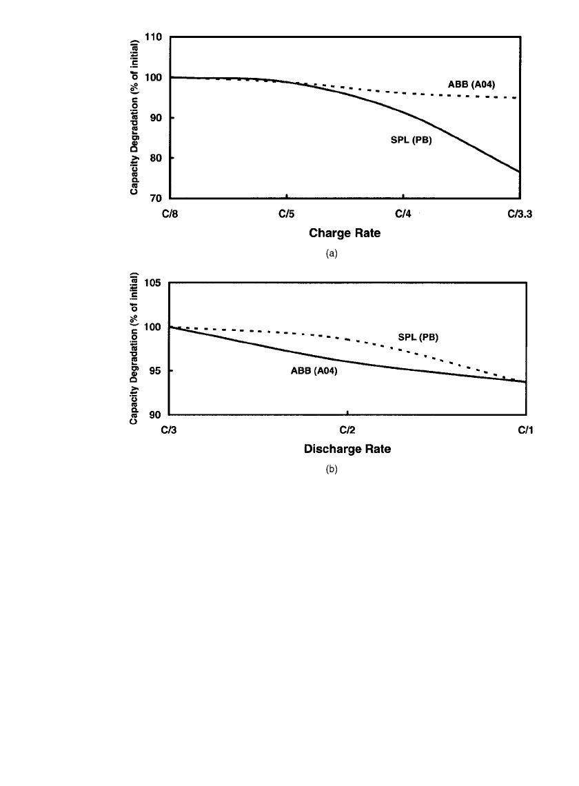
Long-term cycling stability is exhibited by the capacity and resistance response given in Fig.
40.10. Finally, Fig. 40.11 shows that capacity is, in general, not greatly affected by practical
discharge or charge rates. However, the capacity of many cells does decline at charge rates
greater than C/5.
SODIUM-BETA BATTERIES 40.13
FIGURE 40.9 Relationship of specific power to specific energy (Ragone
plot) for two sodium / sulfur cells.
FIGURE 40.10 The effect of cycle life on (a) cell capacity and (b) end-
of-discharge resistance (discharge rate: C/ 3, charge rate: C/5).
40.14 CHAPTER FORTY
FIGURE 40.11 The effect of (a) charge and (b) discharge rate on cell capacity retention.
Sodium/ Sulfur Cell Development
Stationary Energy-Storage Cells. The physical and performance specifications for the
leading cells designed for use in stationary applications are listed in Table 40.4. As will be
further documented in Sec. 40.4, the dominant organization that is presently developing and
commercializing the sodium/sulfur technology is a Japanese collaboration between NGK
Insulator, Ltd and Tokyo Electric Power Company (TEPCO) that started in 1984.
5
Their goal
was to develop cells with sufficient energy capacity for use in utility-based load-leveling and
peak-shaving applications (e.g., TEPCO’s) that require up to an 8-hr discharge period. The
critical technology for such cells involved the manufacture of large diameter beta-alumina
tubes of very high quality and precise dimensions. The capability to manufacture 40-mm
diameter tubes for 160-Ah cells (designated ‘‘T4.1’’) was confirmed and was soon extended
to 45-mm diameter and slightly longer units for use in 248-Ah cells (designated ‘‘T4.2’’).
By 1998, NGK was in the process of developing yet larger cells. This effort has culminated
in a 632-Ah cell (designated ‘‘T5’’) based on 58-mm diameter beta-alumina tubes.
The other active Japanese developers include Yuasa Corporation and Hitachi Ltd. These
organizations originally targeted large-scale utility load leveling as their prime intended use.
Yuasa’s initial effort was part of the national Moonlight Project that resulted in the design
and fabrication of a large number of 300-Ah cells.
6–8
Hitachi has been developing several

SODIUM-BETA BATTERIES 40.15
TABLE 40.4 Specifications for Sodium/ Sulfur Cells Designed for Stationary-
Energy-Storage Applications
Manufacturer NGK NGK NGK YU HIT SPL
Cell designation T4.1 T4.2 T5 — — XPB
Capacity, Ah 160 248 632 176 280 30
Diameter, mm 62 68 91 64 75 44
Length, mm 375 390 515 430 400 114
Weight, g 2000 2400 5400 2700 4000 345
Energy density, Wh/ L 285 340 370 240 300 345
Specific energy, Wh/ kg 160 202 226 120 133 170
Power density, W/ L 36 43 46 60 — 360
TABLE 40.5 Specifications for Sodium/ Beta Cells Designed for
Motive-Power Applications
Manufacturer ABB SPL EPI MES
Cell designation A04 PB — ML3
Prime application
a
EV EV Aero EV
Chemistry Na/ S Na /S Na / S Na / NiCl
2
Capacity, Ah 38 10.5 55 32
Electrolyte shape
b
cyl cyl cyl cruc
Diameter, mm 35 44 36 36.5
Length, mm 220 45 240 232
Weight, g 410 120 590 715
Resistance,
⍀ 6 32 5 6-20
Specific energy, Wh/ kg 176 178 150 116
Specific peak power, W /kg
c
390 250 — 260
a
EV: electric vehicle; Aero: aerospace
b
cyl: cylindrical, cru: cruciform/ fluted
c
at two-thirds open-circuit voltage and 80% DOD
sodium/ sulfur cell designs since 1983. Lately, they have targeted other applications, includ-
ing renewable energy storage.
9,10
Before the discontinuation of their programs in the mid-
1980s, two U.S. companies, Ford Aerospace and Communications Corporation (FACC) and
General Electric, had also been developing large central-sodium cells for utility load-leveling
applications. Silent Power Ltd., a company operating in the U.K. and the U.S, developed a
cell specifically for utility applications that had a nominal capacity of 30 Ah.
11
This cell (the
XPB) was essentially an extended version of their electric-vehicle cell.
Motive-Power (Electric-Vehicle) Cells. Although all development of sodium/ sulfur for
these applications has ceased, the two major participants up through the mid-1990s were
Asea Brown Boveri (ABB) and Silent Power Limited (SPL). The performance of their main
EV cells was discussed in the previous section on Sodium /Sulfur Cell Technology. A com-
pilation of the physical and performance specifications of their cells and Eagle-Picher’s
aerospace cell is included in Table 40.5. During the 1980s, ABB’s A04 cell technology cell
configuration was the building block of their battery program. Innovations included the use
of thermocompression bonding for the electrode seals and aluminum as the primary cell
container. Then, ABB made some subtle, but important, changes to the A04 cell and created
the A08. Discharge of this cell was terminated at 1.87 V open circuit rather than the A04’s

40.16 CHAPTER FORTY
1.76 V. This higher open-circuit cutoff voltage significantly decreased the corrosivity of the
sodium polysulfide active material, permitting the use of lower-cost container coatings.
12
During this same time period, SPL adopted a major change in cell design philosophy to
address problems with freeze-thaw durability and battery reliability (networking considera-
tions). A relatively small, nominally 10-Ah cell resulted that was designated the PB.
40.3.3 Sodium/Nickel-Chloride Cell Technology
A schematic diagram of a sodium /nickel-chloride cell was shown previously in Fig. 40.1b
and a photograph of a modern cell in Fig. 40.6b. In this standard configuration, the sodium
is located on the outside of the

ⴖ-Al
2
O
3
electrolyte (outside sodium). An inside sodium
configuration would require the use of an expensive nickel container. Another advantage of
the outside-sodium cell configuration is that an external cell case with a square cross-section
can be used. This cell geometry permits maximum volumetric packing efficiency within the
battery enclosure to be attained. A third advantage of this configuration is the cell behavior
during thermal ‘‘freeze/ thaw’’ cycling. Here, detrimental tensile stresses on the electrolyte
do not develop, thus effectively eliminating this potential failure mode. The positive electrode
itself is then contained within the electrolyte. In a fully charged cell, this electrode is a
porous nickel matrix that is partially chlorinated to nickel dichloride. The remaining nickel
backbone serves as part of the positive-electrode current collector. About 30% of the nickel
is used in the cell reactions. The matrix is impregnated with the NaAlC1
4
molten salt. The
sodium compartment is less complex than that of the sodium/sulfur cell because safety
features are not needed. The approach to primary containment for both the outer container
and the electrode seals is similar to that with sodium/ sulfur. As discharge proceeds, the
reactions in the positive electrode occur from the outside of the solid nickel structure and
proceed inqard thorugh an ever-increasing thickness of reduced nickel. This shrinking-core
process resuls in an increasing electrical resistance as the cell discharges because the effective
area of the reacting nickel chloride is constantly being reduced. The chemistry of the dis-
charge process provides another significant advantage relative to sodium/ sulfur: cells can be
safely assembled with the discharge products (nickel metal and salt), and then charged.
Also in contrast to the sodium/ sulfur technology, the development of the sodium/metal
chloride system has been pursued by a successive progression of single, integrated organi-
zations for one primary application—electric vehicles. Currently, the prime developer is the
Swiss company, MES-DEA SA. They purchased the technology from AEG Anglo Battery
Holdings (AABH), an organization formed by the German company AEG in cooperation
with the original developers (Zebra Power Systems and Beta R&D Ltd.). This technology is
often referred to as ZEBRA because of its origins. The acronym ZEBRA stands for Zero
Emission Battery Research Activities. To date, development has focused almost exclusively
on the higher voltage nickel variant but using iron as a doping addition to the positive
electrode. As such, the pure iron-based system will not be discussed further in this chapter.
The cell designs that have been developed to date have capacities ranging from 20 to 200
Ah. Specifications for the actual cell design that incorporates the advancements made during
the past five years are listed in Table 40.5. These advancements resulted in an improved
pulse-power capability (especially near the end of discharge) and energy content.
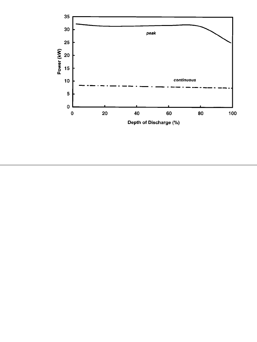
4
At 80%
depth-of-discharge, the power of a modern cell (ML3) is 2.5 times that of a 1992 vintage
cell (SL09). This enhanced level of power performance can be determined by comparing the
cell data previously presented in Fig. 40.3 with modern performance data shown in Fig.
40.12 for a full-sized battery. The most important modifications involved: (1) the use of a
fluted or cruciform-shaped electrolyte that minimized the thickness of the positive electrode
and increased the area of the

ⴖ-Al
2
O
3
electrode; and (2) the introduction of iron as a dopant
to the nickel positive electrode. Optimization of the design and improvements in the chem-
istry of the positive electrode also resulted in a 20 to 40% increase in energy content. The
demonstrated reliability of the early 1990s ZEBRA cells was outstanding with cell failures
virtually non-existent.
SODIUM-BETA BATTERIES 40.17
FIGURE 40.12 Power capability (peak and continuous) as a function of depth of dis-
charge for a modern sodium / nickel-chloride battery (Z5C). (Courtesy of MES-DEA SA).
40.4 BATTERY DESIGN AND PERFORMANCE CHARACTERISTICS
This section on battery-level information is organized the same as Sec. 40.3. That is, battery-
level design considerations specific to the sodium /sulfur technology are presented first. Then,
brief descriptions of modern battery configurations and performance for both sodium-beta
technologies are provided. For reference, a schematic diagram of an integrated sodium /
nickel-chloride battery system was shown previously in Fig. 40.5b.
40.4.1 Sodium/Sulfur Battery Design Considerations
Battery-level components include mechanical supports for the cells, a thermal management
system (incorporating the thermal enclosure) to ensure that each cell is maintained at a
relatively high temperature (e.g., for Na/S from 300
⬚Cto350⬚C), electrical interconnects
(cell-cell, cell-module, module-battery), possibly cell-failure devices, and safety-related hard-
ware (such as thermal fuses). As discussed in the next paragraph, batteries are assembled by
connecting cells into series and series-parallel arrays to produce the required battery voltage,
energy, and power. Electrical heaters are installed within the enclosures to initially warm the
cells and then to offset heat loss during periods while the battery is at temperature, but idle.
Normally, extra heat is not required during regular discharging and charging due to ohmic
heating and chemical reaction effects.
Electrical Networking. During the lifetime of a battery, individual cells will fail, resulting
in a degradation of electrical performance. The rate of degradation is primarily a function
of the failure characteristics of the cells and the electrical networking configuration of the
battery. Some compensation can be provided with additional capacity at the beginning of
life. However, with some battery configurations, especially those with higher voltages (such
as 200
⫹ V), the impact of small numbers of cell failures can be significant. The effects of
cell failure must therefore be mitigated or controlled in the battery.
