Linden D., Reddy T.B. (eds.) Handbook of batteries
Подождите немного. Документ загружается.


METAL / AIR BATTERIES 38.53
50. E. L. Littauer and K. C. Tsai, ‘‘Anodic Behavior of Lithium in Aqueous Electrolytes, ii. Mechanical
Passivation,’’ J. Electrochem. Soc. 123:964 (1976); ‘‘Corrosion of Lithium in Aqueous Electrolytes,’’
ibid. 124:850 (1977); ‘‘Anodic Behavior of Lithium in Aqueous Electrolytes, iii. Influence of Flow
Velocity, Contact Pressure and Concentration,’’ ibid. 125:845 (1978).
51. N. Shuster, ‘‘Lithium-Water Power Source for Low Power Long Duration Undersea Applications,’’
Proc. 35th Power Sources Symp., IEEE, 1992.
52. K. M. Abraham and Z. Jiang, J. Electrochem. Soc. 143, 1 (1996).

39.1
CHAPTER 39
ZINC/BROMINE BATTERIES
Paul C. Butler, Phillip A. Eidler, Patrick G. Grimes,
Sandra E. Klassen, and Ronald C. Miles
39.1 GENERAL CHARACTERISTICS
The zinc/ bromine battery is an attractive technology for both utility-energy storage and
electric-vehicle applications. The major advantages and disadvantages of this battery tech-
nology are listed in Table 39.1. The concept of a battery based on the zinc /bromine couple
was patented over 100 years ago,
1
but development to a commercial battery was blocked by
two inherent properties: (1) the tendency of zinc to form dendrites upon deposition and (2)
the high solubility of bromine in the aqueous zinc bromide electrolyte. Dendritic zinc de-
posits could easily short-circuit the cell, and the high solubility of bromine allows diffusion
and direct reaction with the zinc electrode, resulting in self-discharge of the cell.
Development programs at Exxon and Gould in the mid-1970s to early 1980s resulted in
designs which overcame these problems, however, and allowed development to proceed.
2
The Gould technology was developed further by the Energy Research Corporation but a high
level of activity was not maintained.
3–5
In the mid-1980s Exxon licensed its zinc/ bromine
technology to Johnson Controls, Inc., JCI (Americas), Studiengesellschaft fu¨r Energie-
speicher und Antriebssysteme, SEA (Europe), Toyota Motor Corporation and Meidensha
Corporation (Japan), and Sherwood Industries (Australia). Johnson Controls sold their inter-
est in zinc /bromine technology in 1994 to ZBB Energy Corporation, which is located in the
United States and Australia. Powercell Corporation was formed in 1993, including SEA (now
Powercell GmbH), and is located in the United States, Austria, and Malaysia. The technology
discussed in this chapter is based on the original Exxon design.
39.2 CHAPTER THIRTY-NINE
TABLE 39.1 Major Advantages and Disadvantages of Zinc/ Bromine Battery Technology
Advantages Disadvantages
Circulating electrolyte allows for ease of thermal
management and uniformity of reactant supply to
each cell
Good specific energy
Good energy efficiency
Made of low-cost and readily available materials
Low-environmental-impact recyclable/reusable
components made using conventional
manufacturing processes
Flexibility in total system design
Ambient-temperature operation
Adequate power density for most applications
Capable of rapid charge
100% depth of discharge does not damage battery
but improves it
Near-term availability
Auxiliary systems are required for circulation
and temperature control
System design must ensure safety as for all
batteries
Initially high self-discharge rate when shut
down while being charged
Improvements to moderate power capability
may be needed
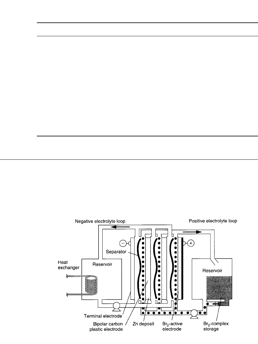
FIGURE 39.1 Schematic of three-cell zinc / bromine module. (Courtesy of Exxon Re-
search and Engineering Co. and Sandia National Laboratories.)
39.2 DESCRIPTION OF THE ELECTROCHEMICAL SYSTEM
The electrochemical reactions which store and release energy take place in a system whose
principal components include bipolar electrodes, separators, aqueous electrolyte, and elec-
trolyte storage reservoirs. Figure 39.1 shows a schematic of a three-cell zinc/bromine battery
system that illustrates these components (plus other features which are discussed in Sec.
39.3). The electrolyte is an aqueous solution of zinc bromide, which is circulated with pumps
past both electrode surfaces. The electrode surfaces are in turn separated by a microporous

ZINC / BROMINE BATTERIES 39.3
plastic film. Thus two electrolyte flow streams are present—one on the positive side and one
on the negative side. The directions of the flow streams may differ depending on the designs
of different companies.
The electrochemical reactions can be simply represented as follows:
(25⬚C) (50⬚C)
Negative electrode
charge
2
⫹
0
—— —
Zn ⫹ 2e Zn
———
discharge
E
0
⫽ 0.763 V 0.760 V
Positive electrode
charge
⫺
—— —
2Br Br (aq) ⫹ 2e
———
2
discharge
E
0
⫽ 1.087 V 1.056 V
Net cell reaction
charge
0
—— —
ZnBr (aq)Zn⫹ Br(aq)
———
2
discharged state discharge
⫽ 1.85 V
0
E
cell
During charge, zinc is deposited at the negative electrode, and bromine is produced at the
positive electrode. During discharge, zinc and bromide ions are formed at the respective
electrodes. The microporous separator between the electrode surfaces impedes diffusion of
bromine to the zinc deposit, which reduces direct chemical reaction and the associated self-
discharge of the cell.
The chemical species present in the electrolyte are actually more complex than that de-
scribed. In solution, elemental bromine exists in equilibrium with bromide ions to form
polybromide ions, , where n
⫽ 3, 5, 7.
6
Aqueous zinc bromide is ionized, and zinc ions
⫺
Br
n
exist as various complex ions and ion pairs. The electrolyte also contains complexing agents
which associate with polybromide ions to form a low-solubility second liquid phase. The
complex reduces the amount of bromine contained in the aqueous phase 10 to 100-fold,
which, in addition to the separator, also reduces the amount of bromine available in the cell
for the self-discharge reaction. The complex also provides a way to store bromine at a site
remote from the zinc deposits and is discussed further in the next section. Salts with organic
cations such as N-methyl-N-ethylmorpholinium bromide (MEMBr) are commonly used as
the complexing agents. One researcher has proposed a mixture of four quaternary ammonium
salts for use in zinc/ bromine batteries. The proposed electrolyte has favorable properties
with regard to aqueous bromine concentration, resistivity, and bromine diffusion and does
not form solid complexes at low temperatures (5
⬚C and above).
7
Complexes with quaternary
ammonium ions are reversible and also have an added safety benefit due to a much reduced
bromine vapor pressure (see Sec. 35.6).
The electrodes are bipolar and are typically composed of carbon plastic. The presence of
bromine precludes the use of metal electrodes—even titanium can corrode in this environ-
ment.
8
A high-surface-area carbon layer is added to the positive side of the electrode to
increase the area for reaction. On charge, circulation of the electrolyte removes the com-
plexed polybromide as it is formed, and on discharge complexed polybromide is delivered
to thee electrode surface. Circulation of the electrolyte also reduces the tendency for zinc
dendrites to form and simplifies thermal management of the battery. Thermal management
will be needed in many applications of present and advanced batteries.
The optimum operating pH range is set by the occurrence of undesirable mossy zinc
plating and bromate formation above pH
⫽ 3, and by an increased zinc corrosion rate at
lower pH. Hydrogen evolution due to the reaction of zinc with water has sometimes been
observed during operation of zinc/bromine batteries. The hydrogen overpotential on zinc is
large, however, and the reaction is slow in the absence of metals with low hydrogen over-
potential, such as platinum.
9
During the development program it was found that the amount
of hydrogen generated was small in the absence of impurities and had a minimal effect on

39.4 CHAPTER THIRTY-NINE
the capacity of the battery.
10
Because of the circulating electrolytes, it would be easy to add
water or acid to the system to compensate for any hydrogen formed, but this has not been
necessary.
In a system where the cells are connected electrically in series and hydraulically in par-
allel, an alternate pathway for the current exists through the common electrolyte channels
and manifolds during charge, discharge, and at open circuit. These currents are called shunt
currents and cause uneven distribution of zinc between end cells and middle cells. This
uneven distribution causes a loss of available capacity because the stack will reach the voltage
cutoff upon discharge sooner than if the zinc were evenly distributed. Also shunt currents
can lead to uneven plating on individual electrodes, especially the terminal electrodes. This
uneven plating can in turn lead to zinc deposits that divert or even block the electrolyte flow.
Shunt currents can be minimized by designing the cells to make the conductive path
through the electrolyte as resistive as possible. This is done by making the feed channels to
each cell long and narrow to increase the electrical resistance. This, however, also increases
the hydraulic resistance and thus the pump energy. Good battery design balances these fac-
tors. Higher electrolyte resistance reduces shunt currents but also reduces battery power.
Since the cell stack voltage is the driving force behind the currents, the number of cells in
series can be set low enough that the magnitude of the shunt currents is minimal. In a specific
utility battery design with 60 cells or less per cell stack, the capacity lost to shunt currents
can be held to 1% or less of the total input energy. When these approaches are not sufficient
to control the shunt currents, protection electrodes can be used to generate a potential gra-
dient in the common electrolyte equal to and in the same direction as that expected from
the shunt current.
10
Several modeling approaches to calculate the currents for various appli-
cations have been proposed.
11–14
39.3 CONSTRUCTION
In general terms the battery is made up of cell stacks and the electrolyte along with the
associated equipment for containment and circulation. The primary construction materials
are low-cost readily available thermoplastics. Conventional plastic manufacturing processes
such as extrusion and injection molding are used to make most of the battery components.
Because terminal electrodes must also collect the current from over the surface and deliver
it to a terminal connection, the lateral conductivity must be higher than in bipolar electrodes,
where the current only passes perpendicularly through the electrodes. A copper or silver
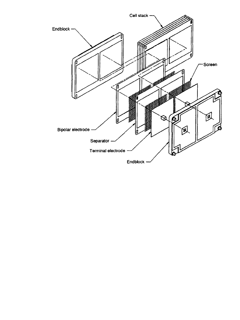
screen is molded into the end block to serve as a current collector. Plastic screens are placed
as spacers between the electrodes and separators. The components are assembled into a
battery stack either by compression using bolts and gaskets, by using adhesives, or by thermal
or vibration welding.
15,16
Assembly of a leak free stack using vibration welding has been
demonstrated by manufacturing cells that can withstand three times the normal operating
pressure before bursting.
17
Figure 39.2 is a schematic showing the components and assembly
of a cell stack.
Various materials have been used for the separator. Ideally a material is needed which
allows the transport of zinc and bromide ions, but does not allow the transport of aqueous
bromine, polybromide ions, or complex phase. Ion-selective membranes are more efficient
at blocking transport than nonselective membranes; thus higher columbic efficiencies can be
obtained with ion-selective membranes. These membranes, however, are more expensive,
less durable, and more difficult to handle than microporous membranes.
10
In addition use of
ion-selective membranes can produce problems with the balance of water between the pos-
itive and negative electrolyte flow loops. Thus battery developers have generally used non-
selective microporous materials for the separator.
3,4,10,15
As shown in Fig. 39.1, two electrolyte circulation circuits are needed for the battery and
include pumps, reservoirs, and tubing. The positive electrolyte side has an additional pro-
ZINC / BROMINE BATTERIES 39.5
FIGURE 39.2 Components and assembly of a cell stack. (Courtesy of Johnson Controls
Battery Group, Inc.)
vision to store polybromide complex, which settles by gravity into a lower part of the res-
ervoir. In Fig. 39.1 complexed polybromide is being delivered to the electrode surfaces during
discharge. During charge, the bulk of the polybromide complex is not recirculated. The
polybromide which is formed at the positive electrode associates with the aqueous-phase
complexing agent and is collected in the storage area of the reservoir. This limits the potential
self-discharge of the battery to only that complex which is in the cell stack at the termination
of the charge process. The bromine may be dissolved in the aqueous phase, absorbed on the
electrode surface, or complexed as polybromide.
A heat exchanger, located in the negative electrolyte reservoir, as shown in Fig. 39.1,
provides for the thermal management of the battery. In general plastic heat exchangers can
be used, and even though titanium corrodes when used as electrode material, titanium has
been used successfully as the tubing material for the heat exchanger.
Ultimately the battery parts will be reclaimed or sent for disposal. The most significant
parts of the battery in this respect are the cell stacks and electrolyte. The battery stacks are
nearly all plastic and can be recycled by conventional processes and new processes that are
being developed by the plastics industry. The electrolyte is not consumed in the battery. It
will be removed and reused in other batteries.
39.6 CHAPTER THIRTY-NINE
39.4 PERFORMANCE
Zinc/ bromine batteries are typically charged and discharged using rates of 15 to 30 mA/
cm
2
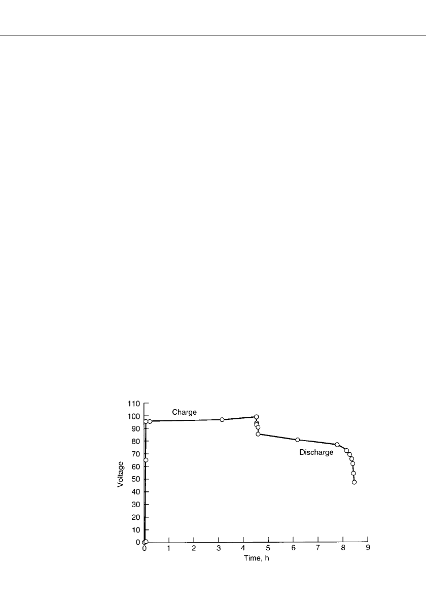
. A charge-discharge profile for a 50-cell stack is shown in Fig. 39.3. The amount of
charge is set based on the zinc loading that is defined at 100% state of charge. This amount
is always less than the total zinc ion dissolved in the electrolyte. Thus rate of charge, time
duration of charge, and charge efficiency are used to determine the end of charge. The voltage
rises at the end of charge, and severe overcharge will electrolyze water. The discharge is
usually terminated at about 1 V per cell since the voltage is falling rapidly at this point.
The capacity of a battery is directly related to the amount of zinc that can be deposited
on the negative electrodes, and zinc loadings can range from 60 to 150 mAh/cm
2
. One
hundred percent state of charge is defined as a specific zinc loading and can vary depending
on the battery. Considerable effort has been expended to ensure good-quality dense zinc
plating. It is important to control the pH to avoid undesirable mossy zinc deposits. Circulation
of the electrolyte reduces the occurrence of dendritic deposits. Studies have shown that
current density, zinc bromide concentration, electrolyte additives, and operating temperature
also affect the quality of the zinc deposit.
4,15
With these studies and improvements, the
problems are being managed or have been eliminated.
Zinc deposited onto a clean carbon plastic surface is smoother than when deposited on
top of zinc; but zinc can be completely removed by total discharge to renew the surface.
This is, in effect, a 100% depth of discharge and does not damage the battery but improves
it. In practical applications the battery should complete many cycles before a strip cycle is
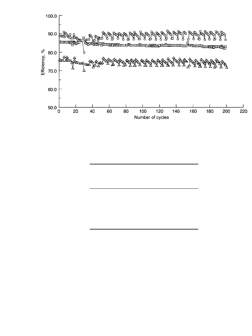
run. A plot of the cycling efficiencies of a 15-kWh battery is shown in Fig. 39.4. The periodic
nature of cycles 60 to 200 is a result of multiple tests in which five cycles were followed
by a strip cycle and also occasionally a baseline cycle. The first new cycle is only slightly
lower in efficiency because the base coat of zinc is being replated.
The amount of ZnBr
2
electrolyte that can be reacted at the electrodes is called the utili-
zation and varies depending on the application. For utility applications battery efficiency is
a primary concern, and percent utilization is about 50 to 70% to maximize efficiency. For
electric-vehicle applications battery size and weight are more important, and the percent
utilization can be as high as 80 to 90%. High utilization results in solutions of lower con-
ductivity at the end of charge, which lowers voltaic and energy efficiencies. Attempts to
charge to very high utilization result in electrolysis of water as a competing reaction, and
high utilization cycles are also opposed because some of the reactant material is isolated in
the opposing electrolyte chamber.
18
FIGURE 39.3 Charge-discharge profile for 50-cell stack. 80% electrolyte
utilization; 30⬚C; 90-mAh / cm
2
zinc loading; 20-mA / cm
2
or C / 4.5 charge
rate; 20-mA/ cm
2
or C / 4 discharge rate. (Courtesy of Sandia National Lab-
oratories.)
ZINC / BROMINE BATTERIES 39.7
FIGURE 39.4 Cycle efficiencies for 15-kWh battery. —coulombic; ▫—voltaic, 䉭—energy. (Courtesy
of Sandia National Laboratories.)
TABLE 39.2 The Effect of Discharge Rate on
Temperature and Energy Output for a 60-cell
Battery Stack
Discharge
current
(A)
Discharge
time
(hours)
Maximum
temperature
(
⬚C)
Energy
output
(kWh)
35.5
42.8
53.3
71.2
104.9
209.9
5.61
4.67
3.75
2.82
1.87
0.82
30.6
31.6
33.2
35.0
39.5
50.9
19.83
19.71
19.43
19.15
17.86
13.54
Source: From Clark, Eidler, and Lex.
19
Battery performance varies with discharge rate. As the discharge rate becomes higher, the
energy efficiency decreases and the temperature of the battery increases. Table 39.2 shows
the effect of rate on temperature and energy output for a 60 cell stack.
19
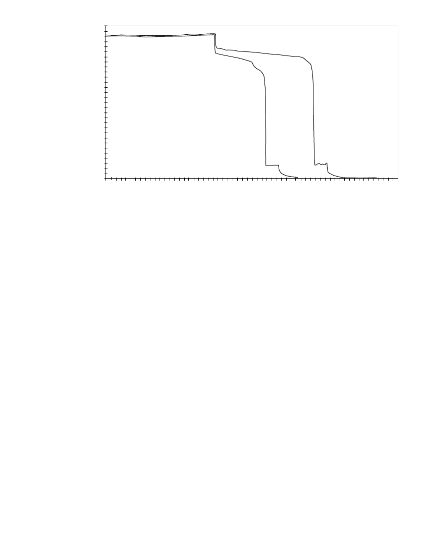
Figure 39.5 shows
the charge and discharge voltage profiles for a 50 A and 100 A discharge of a 60 cell stack.
20
The average voltage and energy efficiency for the 50 A discharge were 98 V and 77%,
respectively. The values for the 100 A discharge are 92 V and 72%, respectively. Calculations
are based on a discharge of 60 V (1 V per cell), and the battery had been charged at a
constant current of 50 A for 4.5 hours prior to both cycles. The average charge voltage was
112 V.
In a battery system a portion of the energy will be diverted to auxiliary systems such as
thermal management, pumps, valves, controls, and shunt current protection as required. The
energy needed for auxiliaries depends on a number of factors, including the efficiency of
pumps and motors, pump run time, and system design. Little publicly available data exist
39.8 CHAPTER THIRTY-NINE
50 AMP CHARGE
120
100
80
60
40
20
0
0123
4
5
67
8
910
11 12
#64 50 AMP
DISCHARGE
TIME IN HOURS
#92 100 AMP DISCHARGE
VOLTAGE
FIGURE 39.5 Charge and discharge profiles for a 50 A and 100 A discharge of a 60 cell stack.
(Courtesy of ZBB Energy Corporation.)
on total energy requirements of auxiliary systems, although the energy devoted to auxiliaries
is projected to be less than a few percent of the total battery energy. ZBB Energy Corporation,
for example, reports that the pump power requirements for a 60 cell stack are just over 1%
of the battery power during discharge at a 100 A rate.
21
In another study, ZBB compared
the performance of the battery when the pumps and controls were powered by the stacks
versus AC.
22
The battery output energy and energy efficiency were 49.5 kWh and 64.5%
when powered by the stacks and 53.3 kWh and 69.3% when powered by AC. It was also
shown that energy efficiency could be raised from 61.3% to 69.8% by using larger pumps
and by making modifications to the plumbing, controls, and manifold system. It should be
noted that other systems have auxiliaries and balancing inefficiencies as well.
Energy will also be lost during stand time. This was measured in one zinc/bromine battery
system to be about 1%/ h (watt-hour capacity lost) over an 8-h period.
16
During the test,
electrolyte, which did not contain the complexed bromine phase, was circulated periodically
to remove heat. The self-discharge reaction ceases once bromine in the stacks has been
depleted.
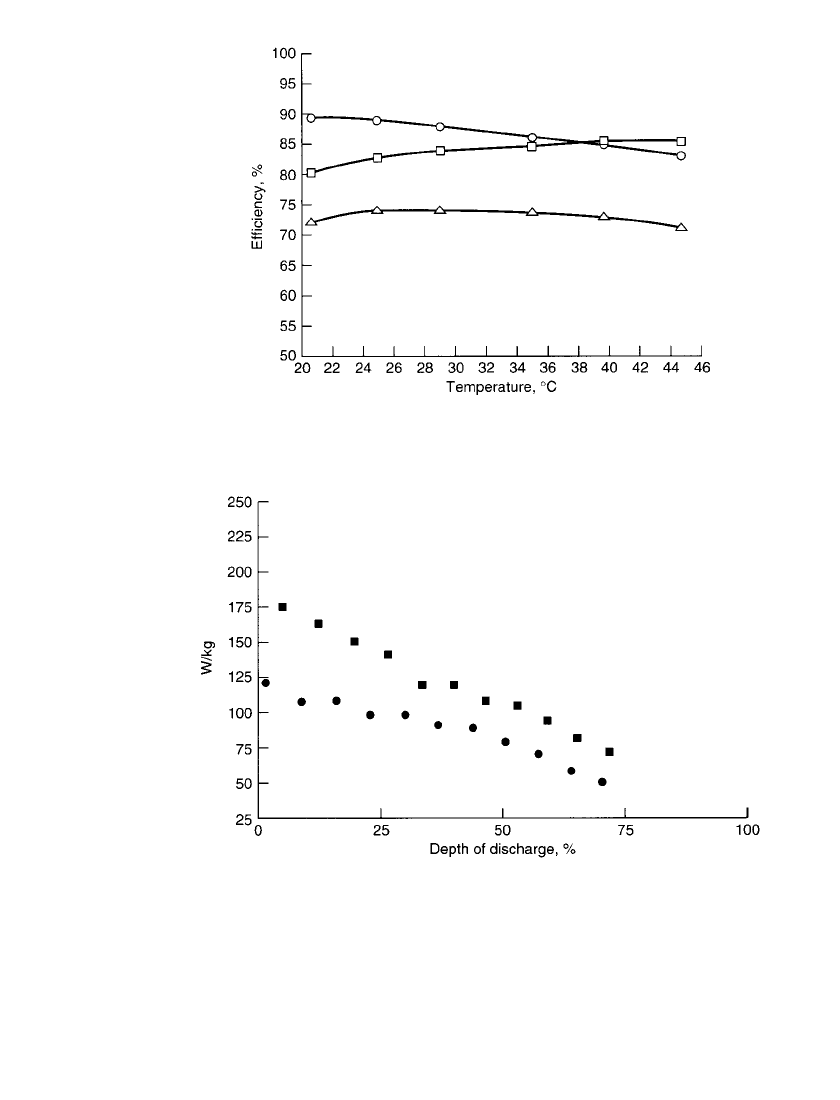
Zinc/ bromine batteries normally operate between 20 and 50
⬚C. Typically the operating
temperature has little effect on energy efficiency, as shown in Fig. 39.6. At low temperature
the electrolyte resistivity increases, resulting in lower voltaic efficiency. This is offset by
slowed bromine transport, which results in higher coulombic efficiency. At high temperature
the resistance decreases and the bromine transport increases, again partially compensating
for each other. Temperature control is accomplished with a heat exchanger and the circulating
electrolyte. The optimum temperature will vary depending on the individual battery design
and electrolyte used.
For applications which require high-power discharges, such as electric vehicles, the con-
ductivity of the electrolyte can be enhanced by using additives such as KCl or NH
4
Cl. In
this way internal ohmic energy losses are decreased. A test using NH
4
Cl supporting electro-
lyte showed more peak power capability than unsupported electrolyte over a range of depths
of discharge, as shown in Fig. 39.7. A Ragone plot of data from sustained power tests is
shown in Fig. 39.8. Batteries with supporting electrolyte, however, do have disadvantages.
Overall efficiencies are about 2% lower than with unsupported electrolyte. Also plating
ZINC / BROMINE BATTERIES 39.9
FIGURE 39.6 Efficiencies vs. operating temperature for battery with
load-leveling electrolyte. —coulombic; ▫—voltaic; 䉭—energy.
(Courtesy of Johnson Controls Battery Group, Inc.)
FIGURE 39.7 Zinc / bromine battery peak power for NH
4
Cl supporting () and
unsupported () electrolyte. Peak power—maximum power that can be achieved for
20 s. 80% electrolyte utilization; 30⬚C; 90-mAh / cm
2
zinc loading. (Courtesy of John-
son Controls Battery Group, Inc.)
additives are needed to counteract the tendency of supported electrolytes to produce rougher
zinc deposits.
15
Since the supporting salts increase the weight and cost of the battery without
increasing the energy content, they would not be added unless the extra power was necessary.
Multicycle and long-term testing is needed to determine the specifications for optimum
operation.
