Linden D., Reddy T.B. (eds.) Handbook of batteries
Подождите немного. Документ загружается.

39.10 CHAPTER THIRTY-NINE
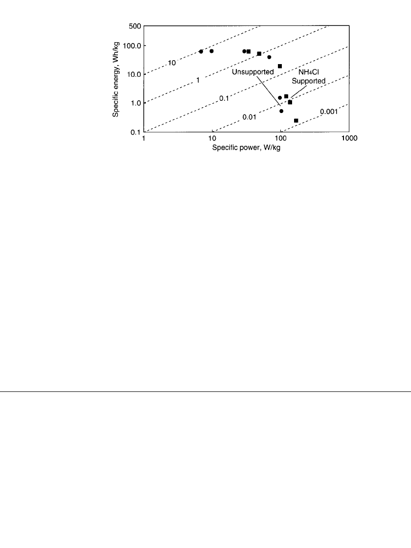
FIGURE 39.8 Zinc / bromine sustained power discharge. 80% electrolyte
utilization; 30⬚C; 90-mAh /cm
2
zinc loading. Diagonal lines denote hours.
(Courtesy of Johnson Controls Battery Group, Inc.)
The largest factor influencing the lifetime of zinc /bromine batteries is most likely the
long-term compatibility of the components with bromine. Improvements have been made in
dealing with degraded seals, corrosion of the terminal current collectors, and warpage of the
electrodes (which can interfere with the flow of the electrolytes), and in many cases problems
have been solved. Studies have been done in a variety of plastic compositions.
3,4,15,23,24
Ad-
ditives which may affect battery performance can be leached out of polyvinylchloride. Fluor-
inated polyolefins are generally chemically stable, but they are expensive, and carbon-loaded
materials are not dimensionally stable in the presence of bromine. High-density polyethylene
with glass fibers appears to be a good choice of materials for battery components from the
viewpoint of chemical and dimensional stability and has displaced polypropylene. With con-
trol of warpage, a battery lifetime of more than 2000 cycles is possible. Studies have also
been done on the stability of the quaternary ammonium salts used as bromine complexing
agents, and decomposition was not found.
10,25
Another study showed that a carbon-plastic
bipolar electrode could tolerate 3000 cycles of zinc deposition and removal without degra-
dation.
3
Battery companies claim 10 to 20 year service lives, which are, of course, influenced
by the application and number of cycles required per year.
20,26
39.5 TRADEOFF CONSIDERATIONS
The zinc/ bromine battery, as do all battery systems, offers a tradeoff between high-rate
discharges and lower-rate discharges; i.e., power and energy. Other additional design trade-
offs can be made. The two most important are increasing the ratio of electrolyte volume to
electrode area to favor energy storage over power, and adding a conductivity salt to the
electrolyte to favor power over energy. There is no clear evidence that operating a zinc/
bromine battery at high power necessarily reduces life. If, however, the battery is allowed
to operate at higher temperatures, plastic material degradation has been observed which does
lead to reduced life. Therefore thermal management is a key issue that has to be addressed
in high-power applications. To be assured of adequate cooling in a high-power application,
larger cooling systems may be needed, which would also increase the battery weight.
The specific energy of the battery may decrease depending on the degree of safety re-
quired. Containment can be enhanced by incorporating multiple barriers to minimize elec-
trolyte loss through a breach. Impact and leak sensors with shut-down controls can be in-
corporated to further ensure that electrolyte circulation ceases in the event of an accident.
All of these additions, however, add weight which contributes to lower specific energy.

ZINC / BROMINE BATTERIES 39.11
39.6 SAFETY AND HAZARDS
Very little free bromine exists in the battery. Bromine is present as polybromide ions dis-
solved in the aqueous portion of the electrolyte or bound with complexing agents in a second
phase. Any remaining bromine is dissolved in the aqueous electrolyte. Liquid or gaseous
bromine is hazardous; it injures through physical contact, especially inhalation.
27
In the
complexed condition, however, the chemical reactivity and the evaporation rate are greatly
reduced from those of pure bromine. For example, at 20
⬚C the vapor pressure of bromine
over the complex with MEMBr is more than 20 times lower than for elemental bromine.
28
If spilled, the charged electrolyte will slowly release bromine from the complex, which in
turn will form vapor downwind from the spill site. Bromine has a strong odor, and it is
readily detected at low levels. Spilled electrolyte can be treated using methods recommended
by qualified industrial hygienists or methods listed in material safety data sheets. The EPA
DOT reportable quantity for zinc bromide spills is 1000 lb.
29
Runaway chemical reactions are unlikely because the polybromide complexes are stored
away from the zinc. Even if the zinc electroplate were somehow flooded with polybromide
complex, the reaction rate of the complex would be relatively slow because of the low zinc
surface are available for reaction.
39.7 APPLICATIONS AND SYSTEM DESIGNS
A great deal of flexibility is available when designing zinc/bromine battery systems. Batteries
can be custom built for a particular application, where multiple modules share a single set
of electrolyte reservoirs or where each module contains a complete system of cell stacks,
reservoirs, and controls. Modules can be stacked to conserve the footprint in energy storage
applications, and reservoirs can be made to match the space available in electric vehicles.
39.7.1 Electric-Vehicle Applications
The Studiengesellschaft fu¨r Energiespeicher und Antriebssysteme (SEA, now Powercell
GmbH) in Mu¨rzzuschlag, Austria, has been developing zinc/ bromine batteries for electric
vehicles since 1983 and has produced batteries with capacities ranging between 5 and 45
kWh.
30
SEA replaced the original Exxon molding of electrolyte channels into the flow frames
with an external tubing manifold system. This allowed a flexible tubing connection of the
stack to the reservoirs and ease of assembly and disassembly. The stacks are in horizontal
layers, allowing low-profile construction. Programmable microprocessor controllers have
been developed to allow thorough, safe, and reliable operation of the systems under various
loads. Systems designed by SEA demonstrate a range of characteristics, as listed in Table
39.3.
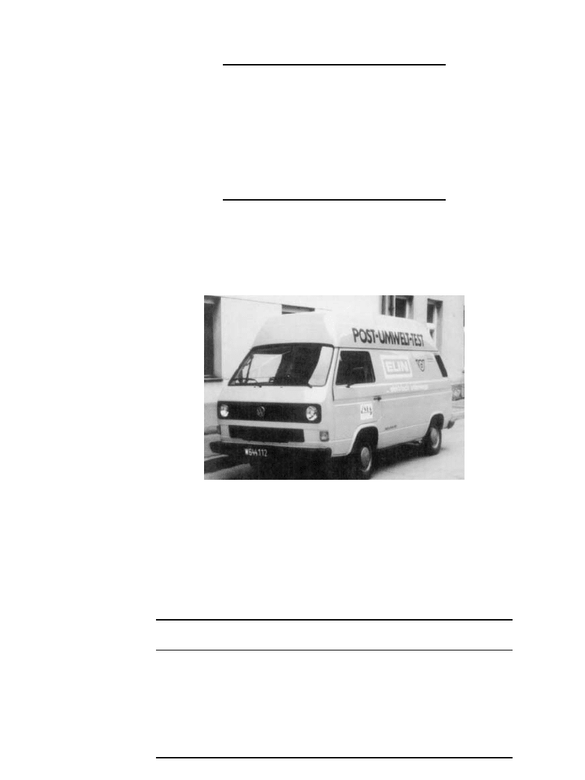
SEA has installed a 45-kWh 216-V battery in a Volkswagen bus which the Austrian Postal
Service has been using to deliver packages in the mountains around Mu¨rzzuschlag (Fig.
39.9). The battery weighs about 700 kg, and the maximum speed achieved by the bus is 100
km/ h. The maximum range at 50 km/ h is 220 km.
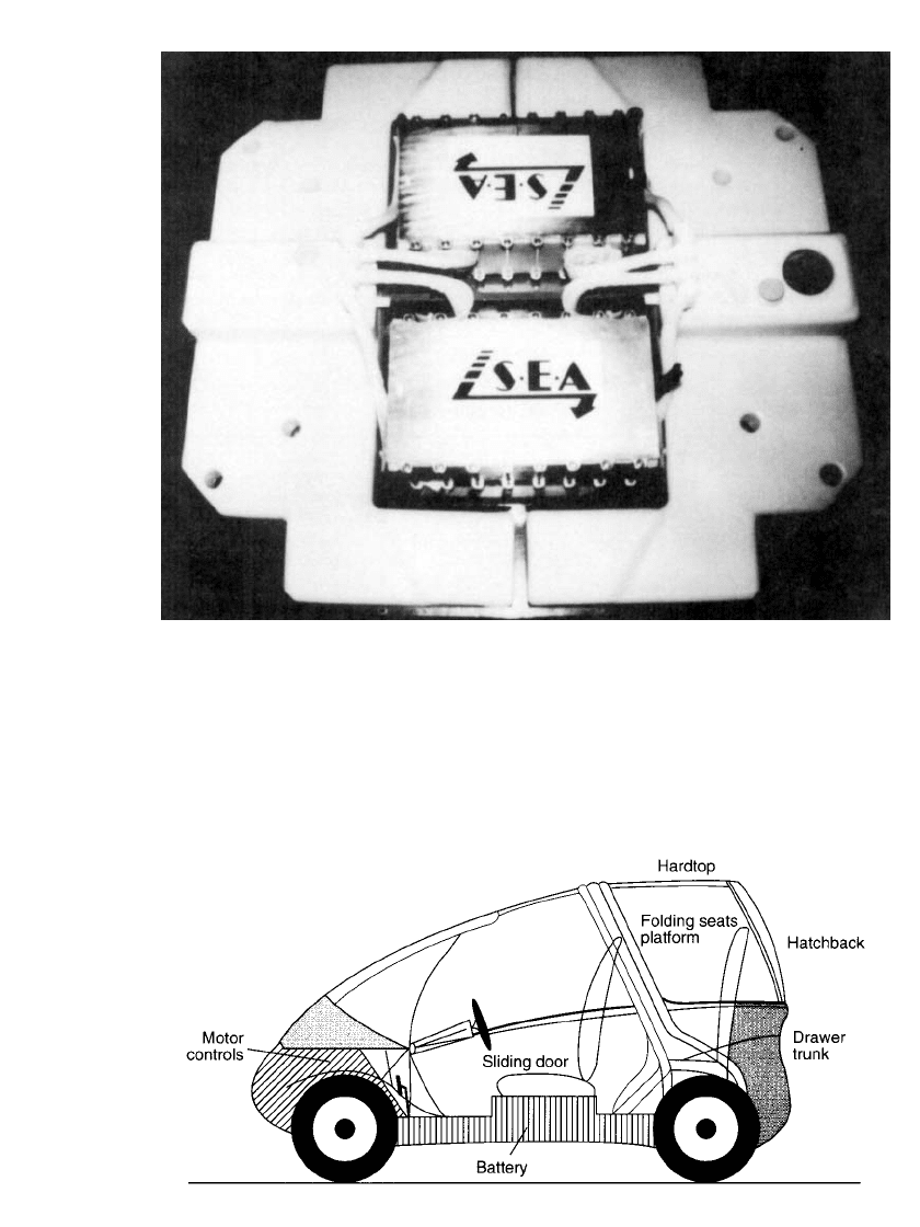
Hotzenblitz, a German company, has designed an electric vehicle to be powered specif-
ically by a zinc /bromine battery (Fig. 39.10). The battery is 15 kWh 114 V and is located
in a compartment under the passenger area, as shown in Fig. 39.11. It is sealed from the
passenger area and is located between side impact barriers for safety. Specifications and
performance data are given in Table 39.4.
39.12 CHAPTER THIRTY-NINE
TABLE 39.3 System Properties for SEA
Designed Zinc/ Bromine Batteries
Cell voltage, theoretical 1.82 V
Cell voltage, nominal 1.5 V
Coulombic efficiency 88–95%
Voltaic efficiency 80–86%
Energy efficiency 68–73%
Gravimetric energy density 65–75 Wh /kg
Volumetric energy density 60–70 Wh/ L
Specific power 90–110 W / kg
Operating temperature Ambient
Source: From Tomazic.
23
FIGURE 39.9 Volkswagon bus powered by SEA zinc/
bromine battery. (Courtesy of SEA.)
TABLE 39.4 Specifications and Performance Data for Hotzenblitz EL
SPORT
Vehicle Battery
Length, 2700 mm Type, zinc-bromine battery
Width, 1480 mm Charging time, approx. 5–6 h
Height, 1500 mm Onboard charger, 3 kW
Gross vehicle weight; approx. 650 kg Battery weight, approx. 240 kg
Payload capacity, 300 kg Speed max.
⬎100 km /h
Range, 150–180 km Gradability, approx. 25%
Motor, 12 kW /144 V
Source: From Tomazic.
30
ZINC / BROMINE BATTERIES 39.13
FIGURE 39.10 SEA 15-kWh 114-V zinc / bromine battery used to power Hotzenblitz EL SPORT.
(Courtesy of SEA.)
FIGURE 39.11 Schematic of Hotzenblitz EL SPORT showing location of zinc / bromine bat-
tery. (From Tomazic.
23
)

39.14 CHAPTER THIRTY-NINE
In the United States, a team at the University of California, Davis, installed a Powercell
30 kWh Zinc-Flow
battery in a Geo Prizm with a Dolphin drive system for the Endura
project.
31
The battery consisted of two stack towers, each containing two 54 cell bipolar
stacks connected in series, two electrolyte tanks and associated pumping systems, and control
and cooling systems. Selected battery specifications are given in Table 39.5. At 391 V, this
is the highest voltage zinc /bromine battery used in an electric vehicle, and the team claims
the Endura is one of the few electric vehicles that is capable of travelling in the high speed
lane of the Los Angeles freeway system. The Endura travelled 175 miles on a single charge,
and the vehicle was capable of accelerating from zero to 100 kilometers (62 miles) per hour
in 15 seconds, and of reaching a velocity of 125 kilometers (78 miles) per hour.
32
The gross
vehicle weight was 1595 kg with a front to rear weight distribution of approximately
50/ 50.
TABLE 39.5 Selected Specifications for the Powercell Endura
Electric Vehicle Battery
Open circuit voltage @ 100% SOC 391 V
Maximum power @ 50% SOC
⬃40 kW
Charge method Constant current
Nominal charge rate 30 amps DC
End of charge voltage 432 V
Nominal charge power 12 kW
Nominal charge time 5 hours (0 to 100% SOC)
Battery specific energy @ C/ 3 rate 65.8 Wh /kg
Source: From Swan, et al.
31
After an extensive safety review,
33
the Endura was entered into several competitions with
successful results. The team placed third in the 1994 Arizona Public Service Electric 500,
first in the 1994 World Clean Air Rally, second in the 1994 American Tour de Sol, and first
in the 1995 Arizona Public Service Electric 500.
31,33
Powercell GmbH asserts that the zinc /bromine technology will be one of the most af-
fordable for electric vehicles.
32
In direct comparison using the same test vehicle fitted with
lead-acid batteries versus Zinc-Flow
batteries, Powercell has been able to show that the
test vehicle will havea2to3fold greater range when fitted with a Zinc-Flow
battery due
to this technology’s reduced weight and higher energy density.
Toyota Motor Corporation has also been developing zinc /bromine batteries for electric
vehicles.
35,39
A concept urban transportation vehicle, called the EV-30, has been designed
for use with Toyota’s zinc/ bromine battery and has been displayed at motor shows in Japan.
This two-seater vehicle would transport people in buildings, shopping centers, small com-
munities, and to and from train stations—a ‘‘horizontal elevator’’ concept. The front-wheel-
drive system uses an AC induction motor built by Toyota Motor Corporation. The battery
system is modular zinc/bromine at 106 V and 7 kWh.
39.7.2 Energy Storage Applications
The use of zinc/ bromine batteries in energy storage applications is also being demonstrated.
A study by Sandia National Laboratories rated the zinc/bromine battery as excellent for
these four utility applications: storage of energy generated by renewable sources, transmis-
sion facility deferral, distribution facility referral, and demand peak reduction.
36
ZINC / BROMINE BATTERIES 39.15
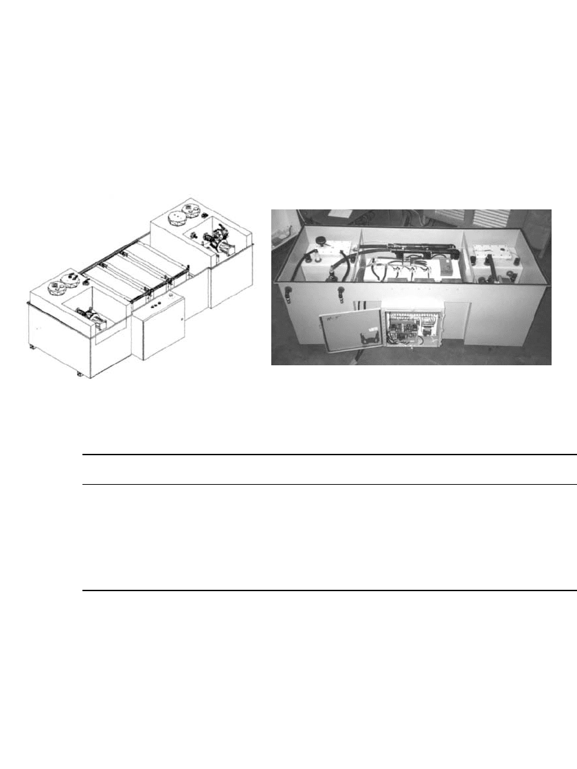
ZBB Energy Corporation has designed and manufactured a 50 kWh battery module that
serves as a building block for larger systems. Each module is made up of three 60 cell stacks
connected in parallel, an anolyte reservoir, a catholyte reservoir, and an electrolyte circulation
system as shown in Fig. 39.12.
20
These modules offer flexibility in building larger batteries
because they can be placed in a variety of series and parallel arrangements. A 400 kWh
battery has been designed for utility demonstrations and consists of two strings connected
in parallel with each string composed of four 50 kWh modules in series. Specifications for
the battery and module can be found in Table 39.6.
20,37
Operation of the battery is flexible
because the power conversion system (PCS) is connected directly to each of the strings
which allows either simultaneous or independent operation.
FIGURE 39.12 Schematic and photograph of ZBB Energy Corporation’s 50 kWh battery module. (Courtesy of ZBB
Energy Corporation.)
TABLE 39.6 ZBB Energy Corporation Battery and Module Specifications
Battery system Module
DC interface 504 volts DC maximum 126 volts DC maximum
Open circuit voltage 432 volts 109 volts
Baseline charge 300 amps for 4.5 hours 150 amps
Capacity 400 kWh—2 hour discharge 50 kWh—2 hour discharge
Dimensions Approx. 2.44 meters
⫻ 2.44 meters
⫻ 5.18 meters
Approx. 2.44 meters
⫻ 0.91 meters
⫻ 0.91 meters
Weight Approx. 18200 kg Approx. 1360 kg
Source: From Lex and Jonshagen
20
and Lex.
37
Future costs for this battery, excluding the PCS, are projected to be $400 /kWh or lower
at modest product levels. The battery is expected to operate for 10 years if cycled five days
per week (2500 cycles) before the stacks and pumps need to be replaced. Replacement costs
are anticipated to be about 20% of the initial cost.
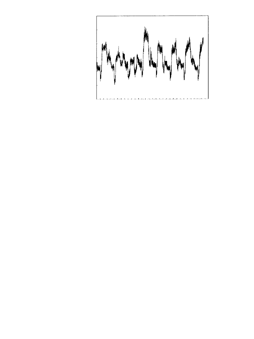
A 400 kWh zinc /bromine battery will be installed at the United Energy Ltd., Nunawading
Electrical Distribution Substation in Box Hill, Victoria, Australia, to shave peaks in the load
curve.
37
A load profile from the Nunawading Substation is shown in Fig. 39.13. Discharge
of the battery during times of peak demand will reduce the transformer load so that equip-
ment ratings aren’t exceeded. The battery can be recharged at night when demand is lower.
Operation in this manner allows costly system upgrades to be deferred.
39.16 CHAPTER THIRTY-NINE
1/3/97 1/4/97 1/5/97 1/6/97 1/7/97 1/8/97 1/9/97 1/10/97
300
250
200
150
100
50
0
Load KVA
FIGURE 39.13 Load profile from the Nunawading Substation,
Australia, January 3–10, 1997. (Courtesy of ZBB Energy Cor-
poration.)
ZBB Energy Corporation also plans a 400 kWh demonstration in the United States and
is working with the Department of Energy and Sandia National Laboratories to evaluate
potential sites.
37
A transportable battery system is an advantage to a utility company because
it can be moved to locations as needs arise. The goal of this demonstration is to use the
battery for peak reduction in the summer at one site and load levelling and power quality
applications during the fall and winter at another site.
Powercell Corporation is also in the process of demonstrating and commercializing zinc/
bromine battery technology for utility applications.
26,38
The company introduced Power-
Block
in 1998, which combines the Zinc-Flow battery technology with solid state power
electronics for quality power output, and a global monitoring system to provide real-time
display of performance as well as data storage. PowerBlock
can be applied to a variety of
electric power issues. PowerBlock
can be used to correct voltage disturbances seen with
intermittent and incessant power quality issues, and can be used to provide protection against
momentary and extended outages. PowerBlock
can also be applied to peak shaving and
other energy service management applications.
A photograph of PowerBlock
is shown in Fig. 39.14, and selected specifications are
shown in Table 39.7.
26
PowerBlocks can serve as modules to build larger systems that can
provide 1 MW of power for 2 hours, for example.
39
These energy storage systems are self-
contained and transportable to allow flexible application. PowerBlock
connections are 480
V, 3-phase (delta) and 112.5 kVA isolation transformers are placed between PowerBlock
and the load and between PowerBlock and the grid or other generating source.
38
PowerBlock is designed for a 20-year service life, and 1250 cycles have been demonstrated
in a single battery.
26
Replacement of the electrode stacks and pump motors will be approx-
imately 15% of the system cost.
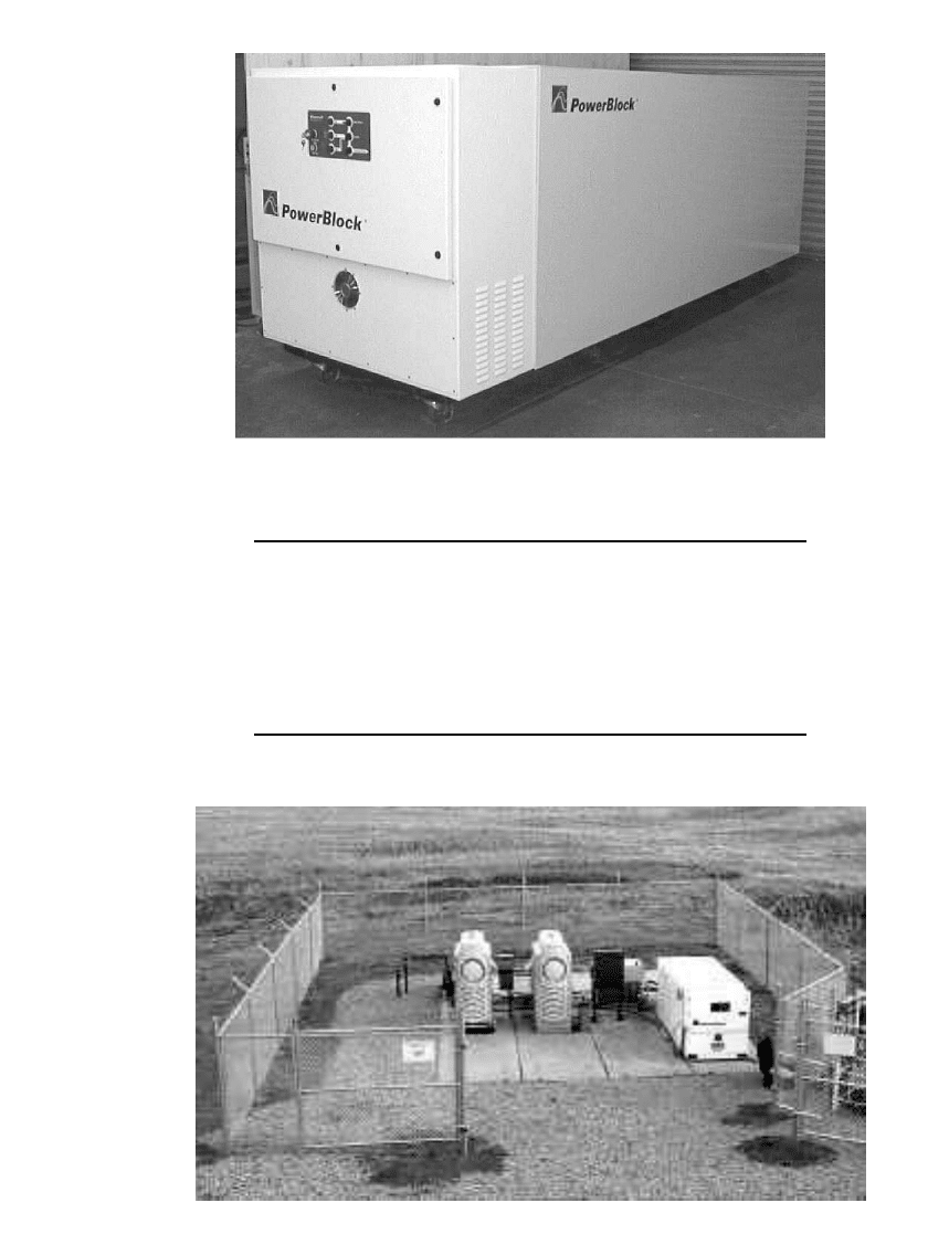
A PowerBlock
module has been installed near the Denver International Airport to store
energy produced by two microturbines that are powered by natural gas from a well on the
property as shown in Fig. 39.15.
40
Installation was completed in three days.
ZINC / BROMINE BATTERIES 39.17
FIGURE 39.14 Photograph of PowerBlock.(Source: From Reference 22.)
TABLE 39.7 Selected PowerBlock Specifications
Continuous power rating 100 kW
Short term (10s) rating 150 kW
Energy capacity 100 kWh @ 25 kW
Recharge time 5 hours
Energy storage efficiency
⬎70%
Ambient conditions 0 to 35
⬚C
Dimensions 3.41 meters
⫻ 1.12 meters ⫻ 1.31 meters
Mass 2670 kg
Source: From Winter.
26
FIGURE 39.15 Aerial view of the PowerBlock module with two microturbines near the
Denver International Airport. (Source: From Reference 22.)
39.18 CHAPTER THIRTY-NINE
In Japan a long-term project to develop zinc/ bromine battery technology for electric-
utility applications has been part of the Moonlight Project under the sponsorship of the
Ministry of International Trade and Industry (MITI).
41,42
During the 1980s research and
development resulted first in 1-kW batteries, then 10-kW batteries, and finally 60-kW battery
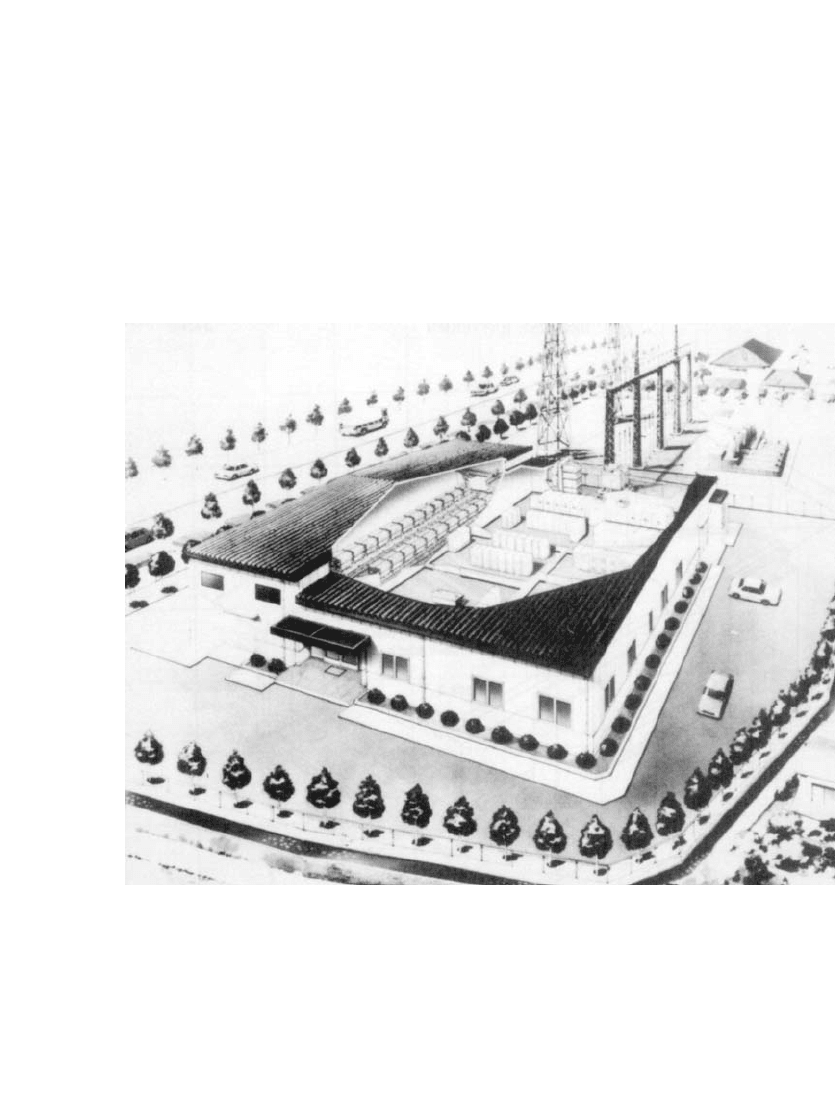
modules. The modules were used as components of a larger system, and in 1990 a 1-MW
4-MWh battery was installed at the Imajuku substation of the Kyushu Electric Power Com-
pany in Fukuoka City by the New Energy and Industrial Technology Develop Organization,
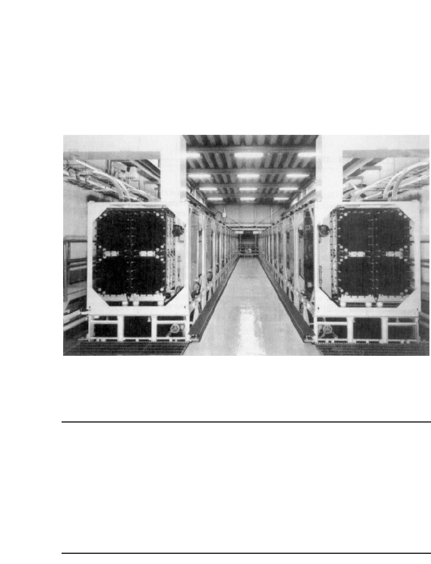
the Kyushu Electric Power Company, and the Meidensha Corporation (Fig. 39.16). The
battery room of the Imajuku energy storage test plant is shown in Fig. 39.17. The system is
composed of 24 25-kW submodules connected in series and is presently the largest zinc/
bromine battery in the world. Design specifications are given in Table 39.8.
43
FIGURE 39.16 Artist’s conception of Imajuku energy storage test plant. (Courtesy of NEDO, Kyushu
Electric Power Co., and Meidensha Corp.)
A typical charging voltage (DC) nominally is about 1400 V with a current of 520 A,
while the discharge starts at 1186 V at an average current of about 900 A.
42,44
Discharge is
terminated when the voltage drops to 720 V. Discharge can be carried out for 8 h at 500
kW or for 4 h at 1000 kW. The 1100-V DC battery output is supplied to a self-commutated
inverter of 1000 kVA, and the output transformer is a self-cooled 1200-kVA type. The AC
output is fed to the Kyushu utility grid in times of peak demand. In periods of low demand
ZINC / BROMINE BATTERIES 39.19
the batteries are recharged from the grid. The battery completed over 1300 cycles with an
overall energy efficiency of 65.9%.
45
MITI has also sponsored a project with Meidensha Corporation and Aisin Seiki Company,
Ltd., to evaluate a 30 kWh zinc/bromine battery module for storage of electrical energy
produced by a solar stirling generator.
46
The intent was to use the battery for lighting at
night and to charge the battery using electric power generated during the day. Results of
field tests at Miyako Island were unsatisfactory due to bad weather; however, tolerance of
this technology to the uneven charge currents generated by solar energy was demonstrated.
FIGURE 39.17 Battery room of Imajuku energy storage test plant. (Courtesy of NEDO, Kyushu Electric
Power Co., and Meidensha Corp.)
TABLE 39.8 Design Specifications for Imajuku Energy Storage Test Plant
Power 1 MW AC
Capacity 4 MWh AC (1000 V AC, 4 h)
Cell electrode area 1600 cm
2
Current density 13 mA /cm
2
(nominal)
Stack 30 cells bipolar
Submodule 25 kW (30 cells in series, 24 stacks in parallel)
Dimensions (height
⫻ width ⫻ length) 3.1 ⫻ 1.67 ⫻ 1.6 m
Weight 6380 kg
Module 50 kW (25-kW submodule, 2 series)
Pilot plant system 50 kW, 12 series
Total weight 153 tons
Source: From Fujii et al.
43