Linden D., Reddy T.B. (eds.) Handbook of batteries
Подождите немного. Документ загружается.

LITHIUM / IRON SULFIDE BATTERIES 41.7
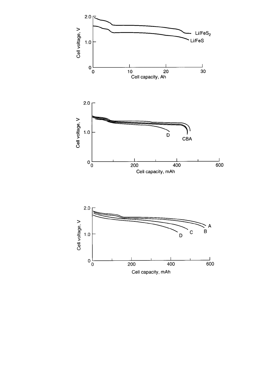
FIGURE 41.3 Voltage vs. delivered capacity plots for 13-cm-
diameter bipolar Li-Al / FeS
x
cells at 425⬚C. (From Kaun et al.)
17
FIGURE 41.4 Voltage vs. delivered capacity plots for 3-cm-diameter
bipolar Li-Al / FeS cell for different discharge rates at 425⬚C. Curve A—
25 mA / cm
2
; curve B—70 mA / cm
2
; curve C—100 mA / cm
2
; curve D—
200 mA / cm
2
.(From Kaun et al.)
17
FIGURE 41.5 Voltage vs. delivered capacity plots for a 3-cm-
diameter bipolar Li-Al / FeS
2
cell for different discharge rates at
425⬚C. Curve A—50 mA / cm
2
; curve B—100 mA/ cm
2
, curve C—
150 mA / cm
2
; curve D—200 mA/ cm
2
.(From Kaun et al.)
17
A very attractive characteristic of bipolar Li-Al /FeS
x
cells is their low impedance, which
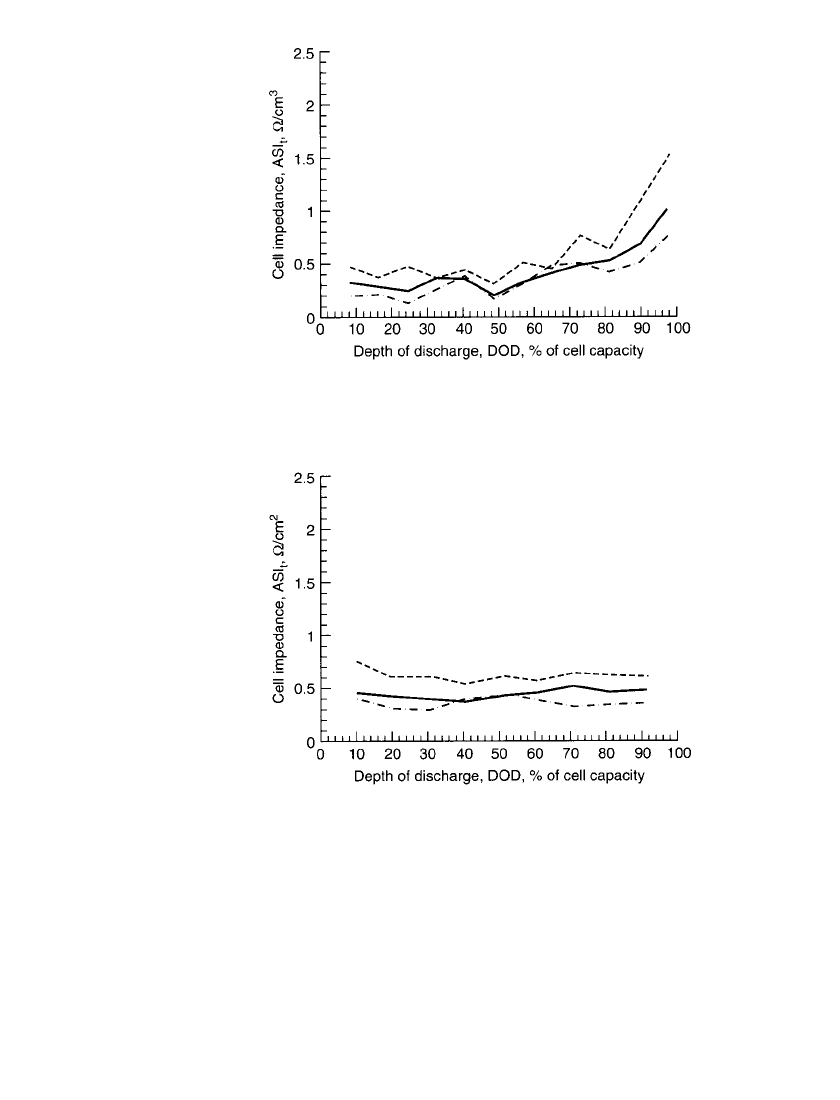
leads to high power capabilities. Figures 41.6 and 41.7 provide cell impedance data as a
function of the depth of discharge for bipolar Li-Al/FeS and Li-Al/FeS
2
cells, respectively.
17
The area-specific impedance (ASI) of Li-Al/ FeS cells remains low through 70% depth of
discharge and then increases through the remainder of the discharge. The ASI of Li-Al/FeS
2
cells remains low throughout the discharge, indicating its ability to deliver high power even
at 90% depth of discharge. A comparison of the 25-ms data to the 1-s data reveals that the
bulk of the impedance is due to an electronic component rather than an ionic component.
This is a direct result of the high conductivity of the electrolyte,
5
1.7 S /cm at 425⬚C, which
is nearly a thousand times greater than that of the lithium-ion organic electrolyte.
41.8 CHAPTER FORTY-ONE
FIGURE 41.6 Cell impedance vs. depth of discharge for 13-
cm-diameter bipolar Li-Al /FeS cell at 425⬚C. Relaxation time t:
---,15s;——,1s;— 䡠 —, 25 ms. (From Kaun et al.)
17
FIGURE 41.7 Cell impedance vs. depth of discharge for 13-
cm-diameter bipolar Li-AL /FeS
2
cell at 425⬚C. Relaxation time
t:---,15s;——,1s;— 䡠 —, 25 ms. (From Kaun et al.)
17
41.4.3 Effect of Temperature
One of the advantages of switching from the LiCl-KCl eutectic electrolyte to the LiCl-rich
LiCl-LiBr-KBr electrolyte is to lower the acceptable operating temperature to 400
⬚C. The
LiCl-LiBr-KBr electrolyte has a melting point of about 320
⬚C and a broad liquidus region
to allow large variations in the Li
⫹
/K
⫹
ratio at 400⬚C. The LiCl-KCl electrolyte has a melting
point of 354
⬚C and requires a cell operating temperature of about 450⬚C. Lower operating
temperatures help extend the calendar and cycle life of lithium /iron sulfide cells. Ambient
conditions have little influence on battery performance because a thermal management sys-
tem is required for this technology.

LITHIUM / IRON SULFIDE BATTERIES 41.9
41.4.4 Self-Discharge
The self-discharge rate of lithium /iron sulfide cells is controlled by the lithium activity of
the Li-Al anode and the rate of transport of dissolved lithium to the cathode. Typical self-
discharge rates for starved-electrolyte cells with 2-mm-thick MgO separators at 425
⬚C are
in the range of 0.1 to 0.2 mA /cm
2
. As described in Sec. 41.4.8, this self-discharge undergoes
a stepwise 20-fold increase as the cell enters into the overcharge-tolerant state. This allows
fully charged cells to endure extended trickle charge at 2 to 5 mA/cm
2
without adding
capacity to the cell.
41.4.5 Power and Energy Characteristics
The starved-electrolyte bipolar configuration leads to high-performance low-burdened Li-Al/
FeS and U.P. Li-Al /FeS
2
cells. The specific energy and specific power characteristics of 13-
cm-diameter sealed bipolar cells are given in Table 41.3. These performance levels are higher
than those achieved in smaller (3-cm-diameter) bipolar cells, indicating an ability to scale
up this technology without sacrificing performance. No additional battery hardware weight
was included in these performance values.
TABLE 41.3 Specific Energy and Power of 13-cm-
Diameter Bipolar Cells
Cell technology
Specific energy,
Wh/kg at W/kg
Specific
power
at 80% DOD,
W/kg
Li-Al/ FeS 130 at 25 240
Li-Al/ FeS
2
180 at 30 400
41.4.6 Cycle Life
The end of life, as typically defined for electric-vehicle batteries, is a 20% loss of capacity
on a standard simulated vehicle driving profile. A commonly used profile is the simplified
federal urban driving schedule (SFUDS). Bipolar 13-cm diameter Li-Al/ FeS
2
cells obtained
over 300 cycles on a modified version of the SFUDS, denoted the Dynamic Stress Test
(DST). Both the FeS and U.P. FeS
2
chemistries have demonstrated the ability to achieve
more than 1000 cycles in flooded-electrolyte prismatic cells when discharged at constant
current.
11,12
As is true for other high-temperature batteries, cycle life is not likely to be
strongly influenced by cycle type.
41.4.7 Efficiency
The coulombic efficiency of Li-Al/FeS
x
cells is controlled by the lithium activity of the
negative electrode and the rate at which dissolved lithium can diffuse across the separator
to the positive electrode. Typically this rate is only 0.1 to 0.2 mA /cm
2
at 425⬚C. This low
self-discharge rate leads to high coulombic efficiency. Similarly, the low impedance of bi-
polar cells (0.5 to 0.7
⍀ 䡠 cm
2
) leads to high voltaic efficiency. Overall the major source of
inefficiency is the heat loss associated with high-temperature operation. Development of a
highly efficient thermal enclosure is necessary for all high-temperature batteries.

41.10 CHAPTER FORTY-ONE
41.4.8 Charging
Development of overcharge-tolerant cells in 1987 to 1988 has significantly minimized pre-
vious charging concerns associated with cell balancing in series-connected strings of cells,
and concerns with regard to preventing the formation of liquid lithium on the negative
electrode during overcharge. A ‘‘smart’’ charger, capable of monitoring individual cells of a
battery and electrically bypassing fully charged cells, was developed and demonstrated on a
36-V prismatic Li-Al /FeS battery.
19
Although technically viable, this approach adds com-
plexity and cost to the battery and the charger. This type of charger is no longer needed
because present cells employ the two-component lithium alloy negative electrodes. When
fully charged, present cells transition to this overcharge-tolerant state, where the lithium
activity of the negative electrode is increased to a level that induces a 20-fold increase in
the self-discharge rate.
5,17
This allows cells to be charged at 2 to 5 mA/ cm
2
without accepting
any additional ampere-hour capacity. Also these cells can be charged at higher rates for short
durations, accepting additional ampere-hour capacity without having liquid lithium form on
the negative electrode. Figure 41.8 shows a voltage versus time trace for a four-cell stack
over three discharge-charge cycles. The second charge half-cycle incorporates an extended
(3-h) trickle charge.
FIGURE 41.8 Stack and cell voltage vs. time plots for four-cell 13-cm-diameter bipolar
Li-Al / FeS
2
stack over three cycles, with 3-h trickle charge at end of second charge half-
cycle. (From Kaun et al.
17
)
41.4.9 Influence of Additives
Additives to the positive electrode can be classified as either inert or active.
8
Inert additives
investigated that were found to be beneficial include graphite fibers and magnesium oxide
powder. Magnesium oxide powder in the positive electrode matrix had the effect of acting
like an electrolyte sponge. It was observed that in cells without the MgO additive, the positive
electrode became electrolyte starved upon repeated cycling. Graphite fibers provided an elec-
tronically conductive matrix within the positive electrode but did not appear to retain as
much electrolyte as the MgO additive.

LITHIUM / IRON SULFIDE BATTERIES 41.11
Active additives CoS
2
and chalcopyrite (CuFeS
2
) reduced the cell area-specific-impedance
(ASI) significantly while providing nearly the same capacity as the FeS
2
removed in its
place. Chalcopyrite is favored over CoS
2
based on its abundance in nature and, hence, low
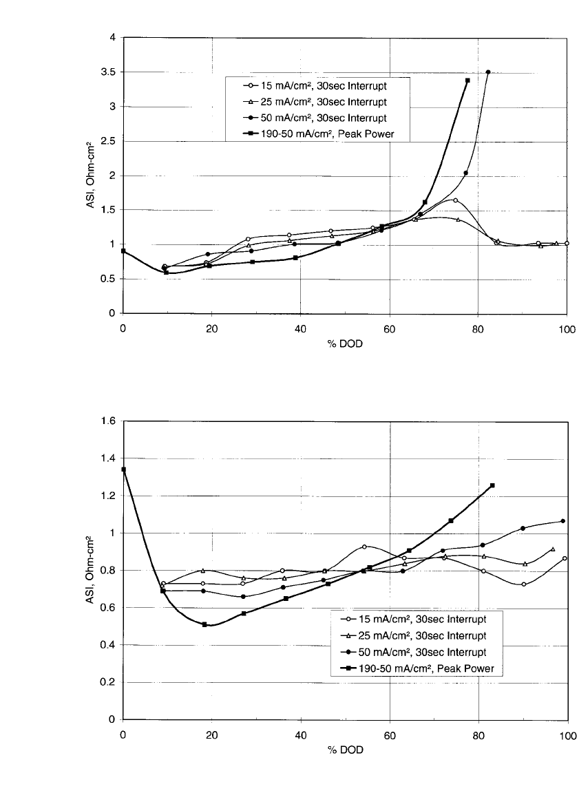
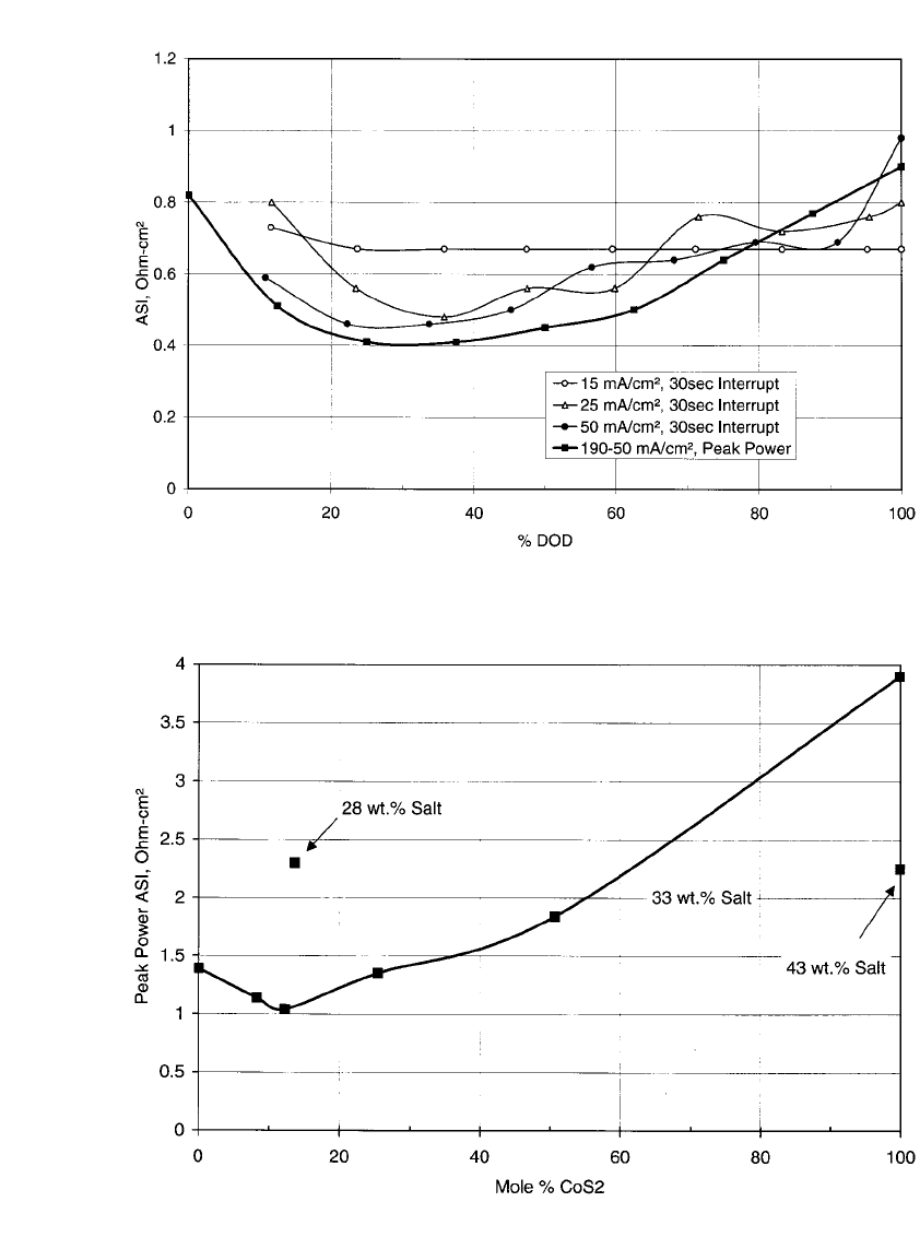
cost. ASI as a function of depth of discharge (DOD) is presented in Figs 41.9 to 41.11 for
cells with positive electrodes that consist of FeS
2
only, 12% CoS
2
additive, and 18% CuFeS
2
additive, respectively. Concern existed over the deposition of Cu in the separator from the
chalcopyrite. To test the impact of this, a 3-cm diameter bipolar cell with 25 mol % CuFeS
2
in the positive electrode was cycled for over 1000 cycles at a C/1 charge and discharge
current rate. The coulombic efficiency remained greater than 99% throughout the life of the
cell. A post-test analysis showed small particles of metallic Cu in the separator, but were
too dispersed to create a short circuit.
8
An optimum concentration of CoS
2
additive in the FeS
2
positive electrode was determined
to be approximately 12 mol %. The optimum concentration of CuFeS
2
additive was found
to be around 12 to 18 mol %. The effect of CoS
2
on the ASI is shown in Figure 41.12 over
the range of 0 to 100% with a salt concentration of 33-wt. % in the cold pressed positive
pellet. Two other data points with different salt concentrations were added to this Figure,
one at 28-wt. % salt in 12:88 molar ratio of CoS
2
: FeS2, and the other at 43-wt. % salt in
100-mol % CoS
2
. The more than doubling of the ASI at 12-mol % CoS
2
additive resulting
from the reduction of the salt concentration by only 5% overwhelms the relatively small
improvement from the CoS
2
additive. Similar comments can be made for the 43-wt. % data
point at 100-mol % CoS
2
.
The addition of CoS
2
required an increase in the concentration of salt in the cold pressed
pellet to prevent the electrode from being too electrolyte starved. This was due to the much
finer particle size and morphology of the synthetic CoS
2
relative to the ground-up naturally
occurring pyrite. These points stress the importance of establishing an optimum salt concen-
tration when operating near starved-electrolyte conditions. Too much electrolyte and the
electrode becomes too fluid (difficult to contain) and the energy density is reduced needlessly.
Not enough electrolyte in the positive electrode results in excessive ASI and poor utilization
of the active materials. Salt concentrations between 28 to 32-wt. % in the positive electrode
were found to be the most practical.
Improvements were made to the LiCl-rich LiCl:LiBr:KBr electrolyte by addition of small
amounts of LiI. The addition of LiF also provided an increase in rate capability of the
electrolyte, but not as much as the LiI.
5
The combination of increasing the electrolyte con-
centration from 28 to 32-wt.% and replacing the CoS
2
with CuFeS
2
had a marked improve-
ment in power capability for this cell technology, as can be seen from an inspection of Fig.
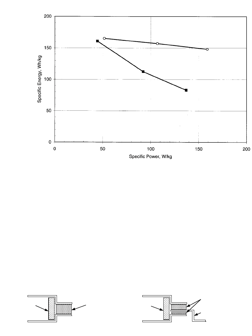
41.13, which is a plot of the specific energy that results from constant power level discharges.
LiI was added to each of these full-size 13-cm bipolar cells. The specific energy and power
levels shown in this figure are based on the total chemistry weight only; no hardware was
added to the weight basis. It was estimated that the hardware would constitute approximately
30-wt. % of the total battery weight. Thus, 160 Wh/kg on a chemistry weight basis would
correspond to approximately 112 Wh/kg on the total battery weight basis.*
*‘‘Total Chemistry Weight’’ is defined as the total weight of all chemicals in the cell
components (negative, separator, and positive), which includes active and inactive materials.
For this system, it is the sum of the LiAl, MgO, Al
5
Fe
2
, LiCl, LiBr, KBr, LiF, Lil, FeS
2
,
CoS
2
, and CuFeS
2
throughout the whole cell. The weight of any hardware or the weight of
the thermal management system are not included mostly because these were not fully de-
veloped but were expected to be approximately 30 percent of the total battery weight. Hence,
160 Wh /kg on a chemistry weight basis would correspond to approximately 112 Wh /kg on
a total battery weight basis as noted in Section 41.4.9. This 30 percent estimate is based on
a large multicell battery, such as in an all electric vehicle. The hardware and thermal man-
agement weight would be a much higher percentage of the battery weight for a battery with
only a few cells.
41.12 CHAPTER FORTY-ONE
FIGURE 41.9 ASI vs. DOD for a 3-cm diameter cell with FeS
2
positive electrode. ASI determined from
30-second current interrupts at various discharge current rates and also from USABC peak power test. (From
Henriksen, et al.
8
)
FIGURE 41.10 ASI vs. DOD for a 3-cm diameter cell with 12-mol % CoS
2
additive to the FeS
2
positive
electrode. ASI determined from 30-second current interrupts at various discharge current rates and also from
USABC peak power test. (From Henriksen, et al.
8
)
LITHIUM / IRON SULFIDE BATTERIES 41.13
FIGURE 41.11 ASI vs. DOD for a 3-cm diameter cell with 18-mol % CuFeS
2
additive to the FeS
2
positive
electrode. ASI determined from 30-second current interrupts at various discharge current rates and also from
USABC peak power test. (From Henriksen, et al.
8
)
FIGURE 41.12 Peak power ASI evaluated at 80% DOD as a function of mole % CoS
2
additive. (From
Henriksen, et al.
8
)
41.14 CHAPTER FORTY-ONE
FIGURE 41.13 Specific energy vs constant power discharge level for 13-cm diameter bipolar LiAl / FeS
2
with additive CoS
2
and 28-wt.% salt in positive electrode —䡲 —, and with additive CuFeS
2
and 32-wt.% salt
in positive electrode —䡩—. Each cell was incorporated with 5-wt.% of LiI (based on total chemistry weight
of cell) (From Henriksen, et al.
8
).
Refined Baseline Seal Advanced Low-Cost Seal
Molybdenum Ring Steel Ring
Steel Ring
Advanced Composite
Ceramic Seal Rings
Locator Ring Ceramic Locator Ring
Seal Ring Molybdenum Cup
Molybdenum Ring
FIGURE 41.14 Baseline and Advanced Low-Cost Seals for a molten-salt bipolar battery. (From Henriksen, et al.
8
)
41.4.10 Chalcogenide Bipolar Seal
A key element of the bipolar battery design is an electrically insulating peripheral seal that
is chemically resistant to attack by the electrode and electrolyte materials. The seal for a
molten-salt bipolar battery must also survive high temperatures and thermal cycling. These
added conditions necessitate the need of a ceramic-to-metal seal. Two seal designs were
developed at ANL;
8
the baseline seal and the advanced low-cost seal depicted in Fig. 41.14.
The baseline seal consists of a Mo-ring /ceramic-ring /Mo-ring construction with an alumina
locator ring that is used to position the ring components while the ‘‘green’’ seal is fired in
a high temperature furnace. Molybdenum bipolar plates are welded to the outside perimeter
of the baseline seal to contain the electrode pellets. The advanced low-cost design replaces

LITHIUM / IRON SULFIDE BATTERIES 41.15
the expensive Mo rings with steel rings and the Mo bipolar plate with a Mo cup to hold the
positive electrode and an optional steel bipolar plate to contain the negative electrode. The
replacement of the Mo rings with steel rings had the additional benefit of welding a steel-
steel peripheral seam instead of a Mo-Mo peripheral seam. Edge welding 125 micron thick
Mo rings together proved to be difficult; the resulting weld was often brittle and rarely
pinhole free.
The ceramic rings used to seal the metal rings together are composed of a mixture of
metal sulfides and ceramic filler. By adjusting the type and ratio of metal sulfides to ceramic
filler, the coefficient of thermal expansion of the ceramic seal is tailored to match that of
the metal rings—a necessity if the peripheral seal is to survive thermal cycling without
cracking. Suitable metal sulfides used include CaAl
2
S
4
,Li
2
CaAl
2
S
5
, YAlS
3
,Ca
2
Al
2
SiS
7
,
LiAlS
2
, and CaY
2
S
4
. Ceramic fillers include MgO, CaO, Al
2
O
3
, AlN, and BN.
18
Combina-
tions of these materials were found to be relatively stable to lithium, mechanically strong,
and good electrical insulators. AlN-based ceramic seals were the most appropriate for the
baseline seal design, while a blend of ceramic fillers was required for the Mo-steel ceramic
‘‘glue’’ used in the advanced low-cost seal design.
41.5 APPLICATIONS AND BATTERY DESIGNS
The predominant interest in bipolar molten-salt lithium/iron sulfide batteries has been for
use in electric vehicles and to a lesser extent, pulse-power applications. This technology can
be readily adapted to various applications that cover a wide range of power-to-energy ratios.
An electric vehicle requires a power-to-energy ratio of approximately 2:1, while a pulse-
power source requires a much higher ratio. A hybrid electric vehicle requires an intermediate
ratio of at least 10:1. These demands could be met by merely varying the thickness of the
electrodes. As is true for other high-temperature batteries, this technology is limited in terms
of its ability to downsize to very small battery sizes. However, this technology may be
capable of downsizing to a greater extent than other high-temperature batteries because of
its shape and compactness.
41.5.1 Pulse-Power Battery Designs
Westinghouse Electric Corporation investigated the use of a bipolar lithium-alloy /metal di-
sulfide battery to be used by the U.S. Army for pulse-power applications.
20
Tape casting
methods were used to fabricate the electrodes and separators, rather than the cold-pressed
powder plaque methods described in Sec. 41.3, which required presses with
⬎500 tons of
force capability. A high melting-point (445
⬚C) high-conductivity LiF-LiCl-LiBr electrolyte
was used to achieve maximum power. This effort resulted in the demonstration of a 40-V,
5-kW, 67-Wh module that consisted of 20 cells each with an area of 150 cm
2
. Northrop
Grumman Corporation, which acquired Westinghouse’s battery operation, redirected this ef-
fort to the investigation of rechargeable fused salt batteries for undersea vehicles for the U.S.
Office of Naval Research.
21
Molten salt batteries are well suited for this application because
of their inherently long storage life and high power capability. CoS
2
was used in the positive
electrode instead of FeS
2
because of its superior thermal and chemical stability in the high
melting point electrolyte. A sintered aluminum-nitride separator was developed with Ad-
vanced Refractory Technologies, Inc. as an alternative to the MgO powder and boron-nitride
felt separators. Sintered separators measuring 15-in diameter were produced with a thickness
of 0.05 in and a porosity of 36%. However, this new type of separator had limited success
during cell operation.

41.16 CHAPTER FORTY-ONE
SAFT R&D Center also directed efforts into the development of rechargeable high-power
LiAl/ FeS
2
batteries for military use.
22
The SAFT pulse-power battery technology is more
similar to the electric-vehicle battery technology described in Sec. 41.3. Cold-pressed powder
plaques were used for the electrodes and the separators. Like Westinghouse and Northrop
Grumman, SAFT used the high melting-point (445
⬚C) high-conductivity LiF-LiCl-LiBr elec-
trolyte. Unfortunately, due to the appeal of the relatively new ambient-temperature recharge-
able batteries, all three organizations have discontinued further efforts in developing re-
chargeable high-temperature batteries.
41.5.2 Electric-Vehicle Battery Designs
The design and construction of bipolar lithium /iron sulfide cells and stacks are described in
Sec. 41.3 and illustrated in Fig. 41.2. Cells and stacks employing electrodes and electrolyte/
separator pellets with 125-cm
2
area have been built and tested. Four-cell stacks of this size
have been fabricated in the manner described in Sec. 41.3. The chalcogenide-based ceramic-
to-metal peripheral seals have been successfully implemented on these stacks, the diameter
of which appears suitable in size for many electric-vehicle applications. The optimal cell
size, stack size, and module size will be dictated by the specific requirements and constraints
established by the vehicle and its power electronics and control system. Fully integrated
bipolar battery modules that incorporate their own thermal management systems have not
been built and tested for either the electric-vehicle or pulse-power applications. However,
several bipolar battery design and analysis studies have been conducted based on the engi-
neering experience gained in the design and fabrication of prismatic lithium/iron sulfide
electric-vehicle battery modules.
The U.S. Advanced Battery Consortium (USABC) established primary and secondary
criteria for mid-term and long-term electric-vehicle batteries. These criteria, listed in Tables
41.4 and 41.5, do not incorporate any specifications in terms of battery size, capacity, or
voltage. Three types of vehicles are selected here for use in discussing battery designs: a
light-duty electric van, a high-performance passenger car, and a hybrid vehicle. These three
vehicles were selected because they span the range of power-to-energy ratios being consid-
ered for on-road transportation vehicles that utilize battery energy storage. General battery
requirements for these vehicles are provided in Table 41.6. The power-to-energy ratio for
the light-duty van battery is approximately 1:1, while that for the hybrid vehicle is approx-
imately 6:1. This hybrid vehicle is of the type where the battery possesses the full power
capability to accelerate the vehicle and provide an appreciable zero-emission (battery-only)
range. If employed as part of a hybrid-vehicle propulsion system in a high-performance high-
efficiency passenger car, similar to the General Motors Impact, a battery meeting the hybrid-
vehicle requirements could provide a greater than 190 km zero-emission range. If a car
similar to the Impact were used as the high-performance all-electric passenger car, a battery
meeting the high-performance electric-vehicle requirements could provide a 290 km zero-
emissions range. The battery requirements for a light-duty van are those established by the
U.S. Department of Energy for high-performance advanced batteries in the IDSEP van.
23
While the hybrid-vehicle requirements listed in Table 41.6 were appropriate during the de-
velopment of the LiAl /FeS
2
battery, the current strategy of the U.S. auto industry under the
Partnership for a New Generation of Vehicles (PNGV) is to develop dual-mode hybrid-
electric vehicles that have much reduced zero emission range. The PNGV battery requirement
of such a vehicle is an available energy of 1.5 kWh in a 65-kg battery pack.
