Lalanne C. Mechanical Vibrations and Shocks: Mechanical Shock Volume II
Подождите немного. Документ загружается.

264
Mechanical
shock
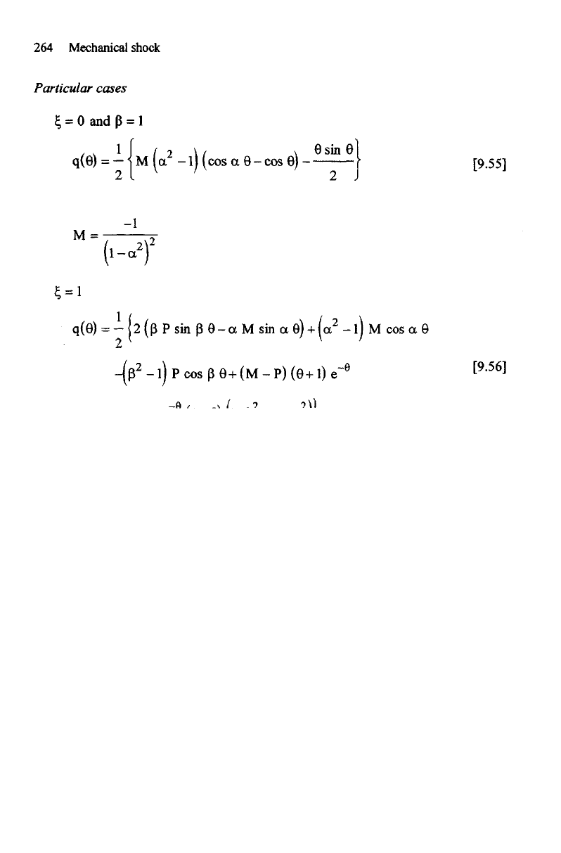
Particular cases
Let us
set,
for
For
where:
and
Control
of a
shaker
using
a
shock response
spectrum
265
9.5.3.2.
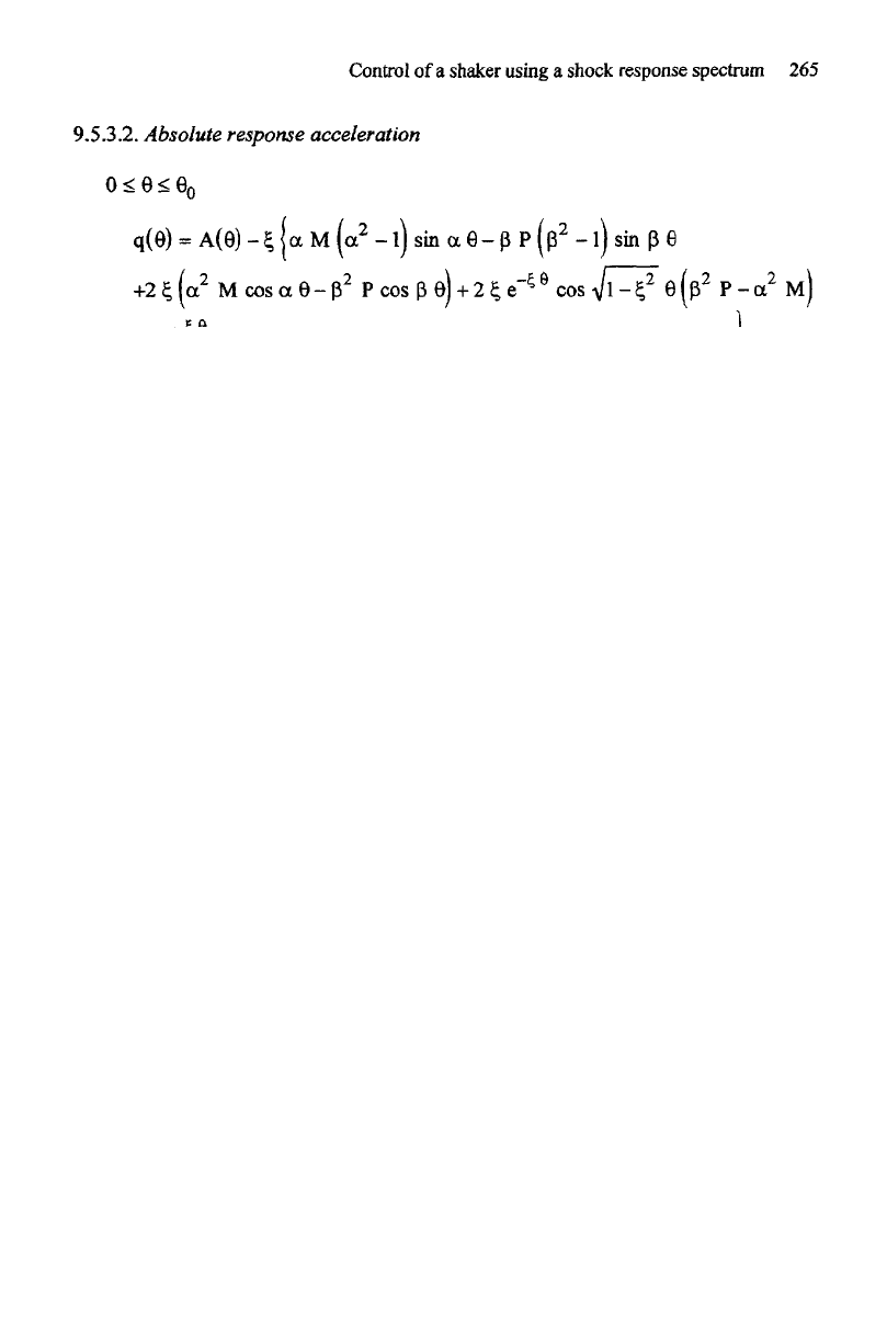
Absolute response acceleration
Particular
cases
E
=
0 and B = 1: the
same relations
as for the
relative displacement
E
=
l
9.5.4. Response spectrum
The SRS of
this waveform presents
a
peak whose amplitude varies with
N
with
its frequency
close
to f.
Figure 9.25 shows
the
spectra
plotted
in
reduced coordinates
for N = 3, 5, 7 and
9(Q
=
10).
For
all the
cases where
0 < 9 < 6
0
, let us
set:
It
becomes,
for 9 > 0
0
:

266
Mechanical shock
Figure
9.25.
WAVSIN
-
influence
of
the
number
of
half-cycles
N on the SRS
Figure
9.26.
WAVSIN
-
amplitude
of
the
peak
of
the
SRS
versus
N and Q
Figure
9.26 gives
the
value
of the
peak
of the
shock spectrum R(Q,
N)
standardized
by the
peak R(10,
N)
according
to the
half-cycle number
N, for
various values
of Q
[PET 81].
9.5.5.
Time
history
synthesis
from shock
spectrum
The
process
consists here
of
choosing
a
certain number
n of
points
of the
spectrum
of
reference and,
at the frequency of
each
one of
these points, choosing
the
parameters
b, N and a
m
to
correspond
the
peak
of the
spectrum
of the
elementary
waveform
with
the
point
of the
reference spectrum. This operation being carried
out
for
n
points
of the
spectrum
of
reference,
the
total signal
is
obtained
by
making
the
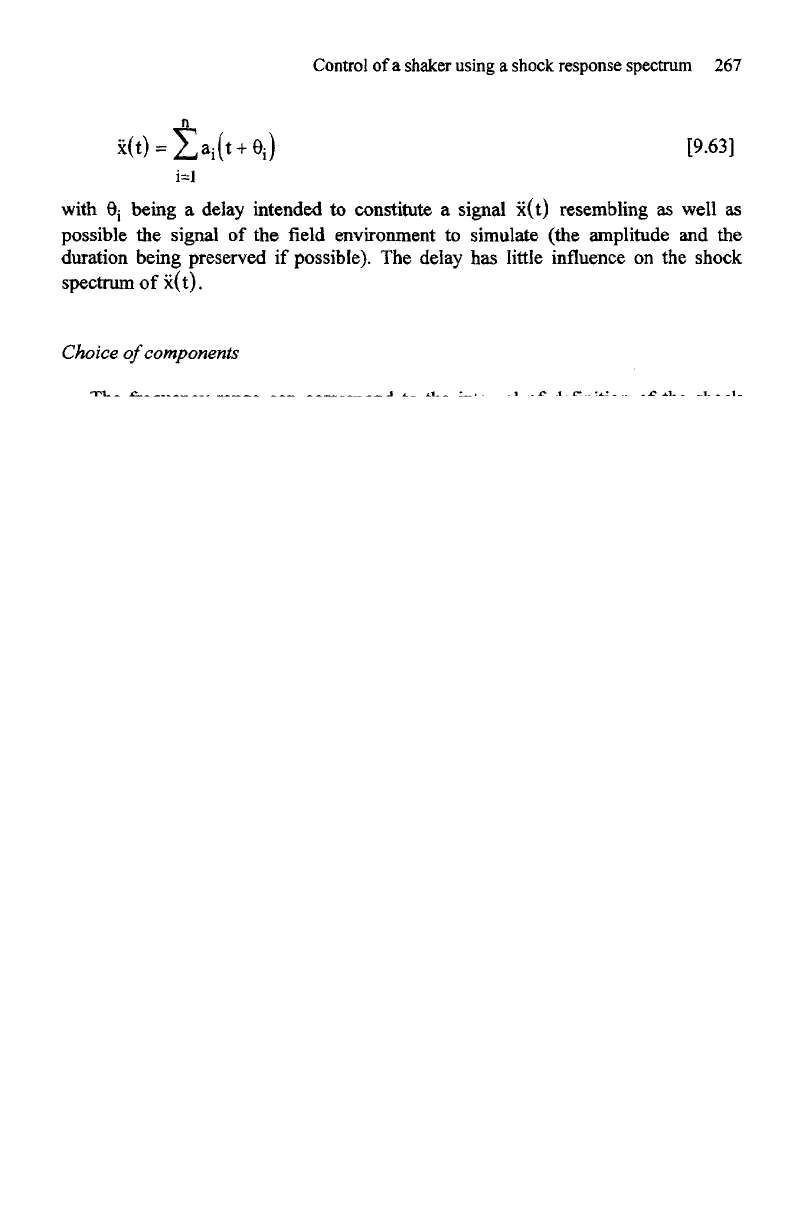
sum:
s
Control
of a
shaker using
a
shock
response
spectrum
267
with
6j
being
a
delay intended
to
constitute
a
signal x(t) resembling
as
well
as
possible
the
signal
of the field
environment
to
simulate (the amplitude
and the
duration
being preserved
if
possible).
The
delay
has
little influence
on the
shock
spectrum
of
x(t).
Choice
of
components
The frequency
range
can
correspond
to the
interval
of
definition
of the
shock
spectrum
(1/3
or 1/2
octave). Convergence
is
faster
for the 1/2
octave. With
1/12
octave,
the
spectrum
is
smoother, without troughs
or
peaks.
The
amplitude
of
each component
can be
evaluated
from the
ratio
of the
value
of
the
shock spectrum
at the frequency
considered
and the
number
of
half-cycles
chosen
for the
signal [BAR 74].
a
mi
allows
a
change
of
amplitude
at all the
points
of the
spectrum.
Ni
allows modification
of the
shape
and the
amplitude
of the
peak
of the
spectrum
of the
elementary
waveform
at the frequency fi.
The
errors between
the
specified spectrum
and the
realized spectrum
are
calculated
from an
average
on all the
points
to
arrive
at a
value
of the
'total'
error.
If
the
error
is
unacceptable,
one
proceeds
to
other iterations. Four iterations
are in
general sufficient
to
reach
an
average error lower than
11%
[FAV 74]. With
the
ZERD
waveform,
the
WAVSIN pulse
is
that which gives
the
best results.
It
is finally
necessary
to
check before
the
test
that
the
maximum velocity
and
displacement corresponding
to the
drive acceleration signal remain within
the
limits
of
the
test
facility
(by
integration
of
x(t)).
9.6. SHOC
waveform
9.6.1.
Definition
Method SHOC (SHaker Optimized
Cosines)
suggested
by
D.O. Smallwood
[SMA
73], [SMA 74a], [SMA
75] is
based
on the
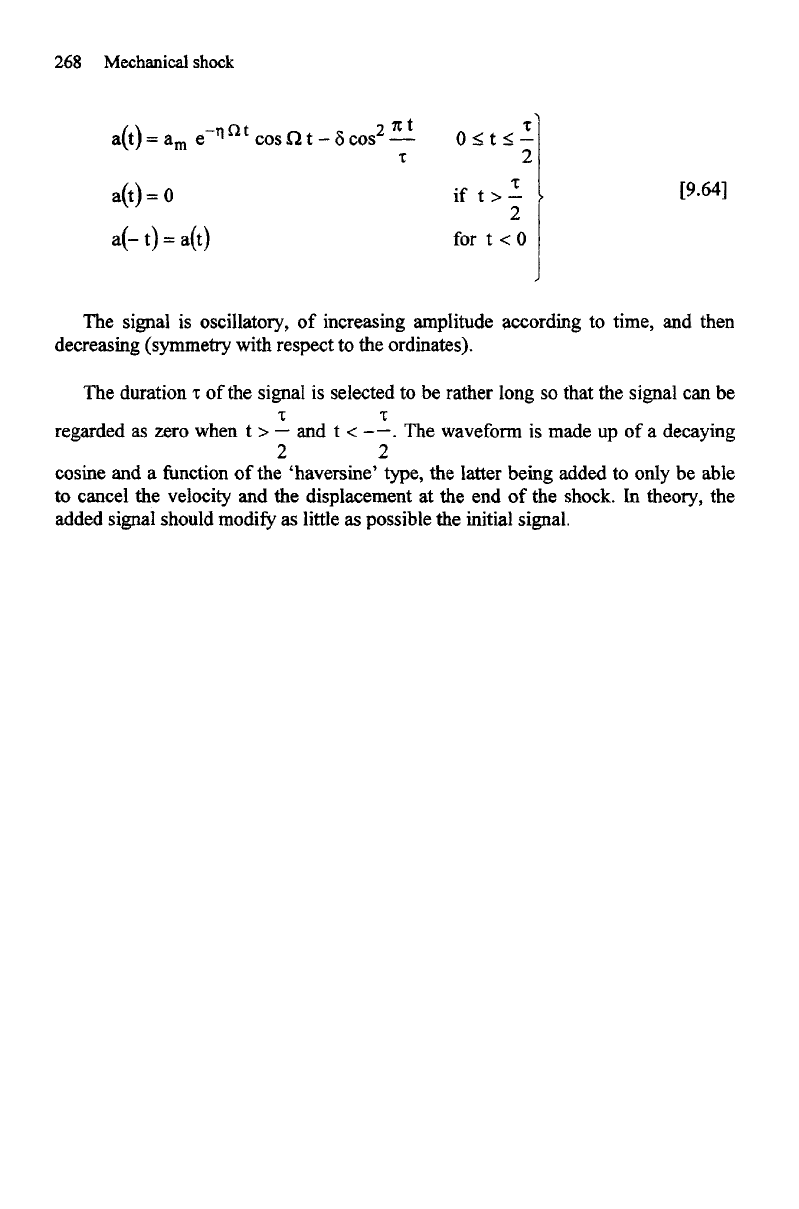
elementary waveform defined
by:
268
Mechanical shock
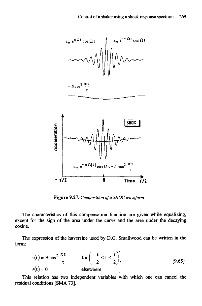
The
signal
is
oscillatory,
of
increasing amplitude according
to
time,
and
then
decreasing (symmetry with respect
to the
ordinates).
The
duration
t of the
signal
is
selected
to be
rather long
so
that
the
signal
can be
t
regarded
as
zero when
t >
—
and t < -—. The
waveform
is
made
up of a
decaying
2 2
cosine
and a
function
of the
'haversine'
type,
the
latter being added
to
only
be
able
to
cancel
the
velocity
and the
displacement
at the end of the
shock.
In
theory,
the
added signal should
modify
as
little
as
possible
the
initial signal.
Control
of a
shaker using
a
shock
response
spectrum
269
Figure
9.27. Composition
of
a
SHOC
waveform
The
characteristics
of
this compensation
function
are
given while equalizing,
except
for the
sign
of the
area under
the
curve
and the
area under
the
decaying
cosine.
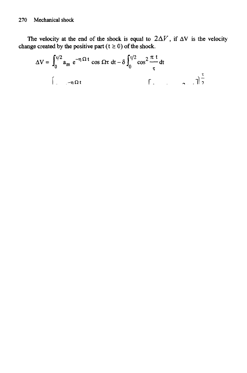
The
expression
of the
haversine used
by
D.O. Smallwood
can be
written
in the
form:
This relation
has two
independent variables with which
one can
cancel
the
residual conditions [SMA 73].
270
Mechanical shock
The
velocity
at the end of the
shock
is
equal
to
2AV,
if AV is the
velocity
change
created
by the
positive part
(t > 0) of the
shock.
being sufficiently large
AV
is
zero
at the end of the
shock
if:
The
largest value
of
a(t) occurs
for t = 0 :
a(o)
= a
m
- 8
9.6.2.
Velocity
and
displacement
By
integration
of the
acceleration:
we
obtain
the
velocity
and
the
displacement
Control
of a
shaker using
a
shock response spectrum
271
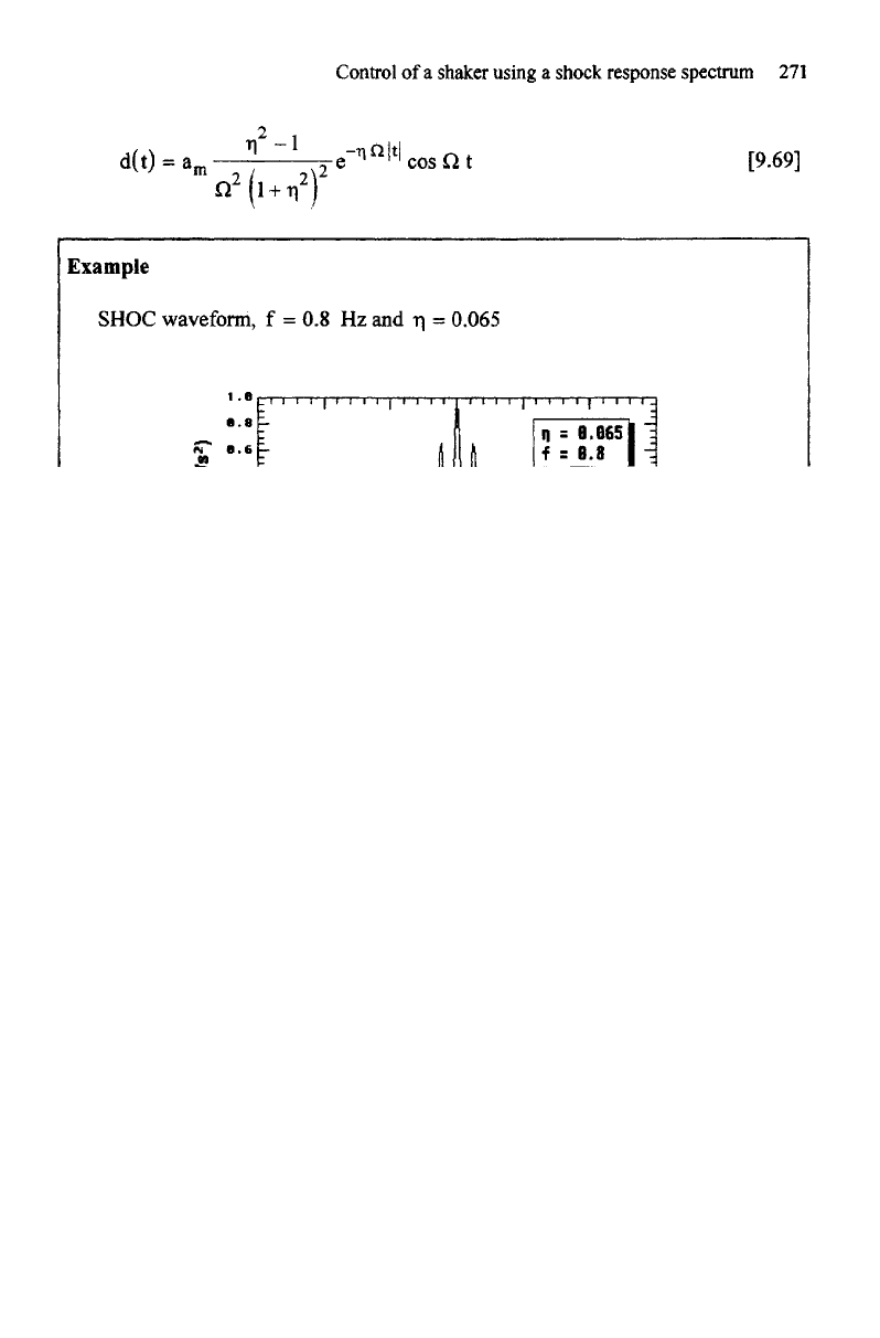
Example
SHOC
waveform,
f = 0.8 Hz and n =
0.065
Figure
9.28. Example
of
SHOC
waveform
9.6.3.
Response spectrum
9.6.3.1.
Influence
of
damping
n
of
the
signal
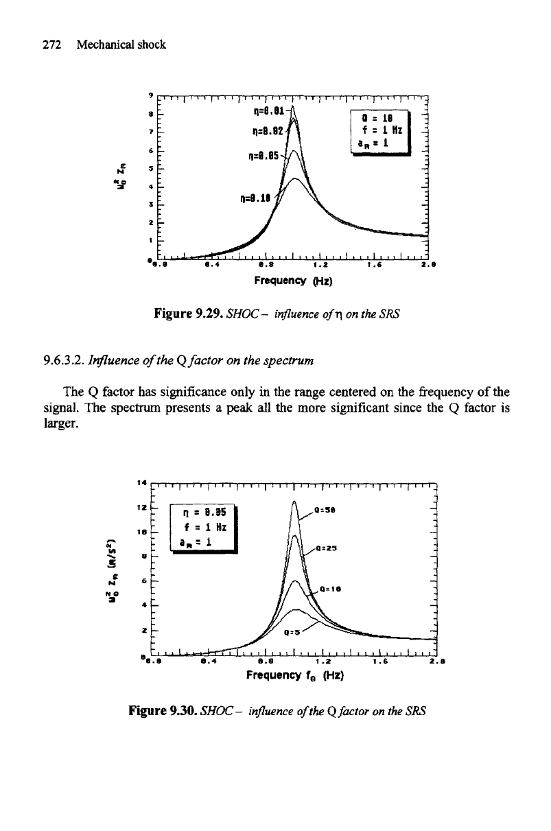
Figure
9.29 shows
the
response spectra
of a
SHOC waveform
of
frequency
1 Hz
with
damping factors
n
successively equal
to
0.01, 0.02, 0.05
and
0.1. These spectra
are
plotted
for Q = 10. We
observe
the
presence
of an
important peak centered
on
D
the frequency f =
whose amplitude varies with
n.
2 n
272
Mechanical shock
Figure
9.29.
SHOC
-
influence
of n on the
SRS
9.6.3.2.
Influence
of
the Q
factor
on the
spectrum
The
Q
factor
has
significance only
in the
range centered
on the frequency of the
signal.
The
spectrum
presents
a
peak
all the
more significant since
the Q
factor
is
larger.
Figure
9.30. SHOC-
influence
of
the
Q
factor
on the SRS
Control
of a
shaker using
a
shock response spectrum
273
9.6.4.
Time
history
synthesis
from shock spectrum
To
approach
a
point
of the
shock spectrum
to
simulate,
we
have
the
following
parameters:
-
damping
n
for
the
shape
of
the
curve;
- the frequency f, at the
point
of the
spectrum
to be
reproduced;
- the
amplitude
a
m
,
related
to the
amplitude
of the
spectrum
(scale
factor
on the
whole
of the
curve);
-
duration
T,
selected
in
order
to
limit
the
maximum displacement during
the
shock according
to the
possibilities
of the
test
facility.
In
fact,
n and T are
dependent
since
one
also requires that
at the
moment
T / 2 the
decaying cosine
be
near
to
zero.
Considering
the
envelope,
one can for
example
ask
that with
t / 2, the
amplitude
of
the
signal
be
lower than
p% of the
value with
t = 0
yielding:
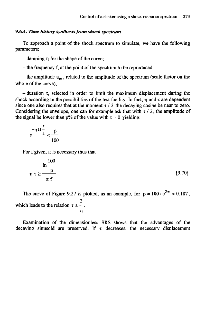
For f
given,
it is
necessary thus that
The
curve
of
Figure 9.27
is
plotted,
as an
example,
for
which
leads
to the
relation
Examination
of the
dimensionless
SRS
shows that
the
advantages
of the
decaying sinusoid
are
preserved.
If T
decreases,
the
necessary displacement
decreases
and,
as the low frequency
energy
decreases,
the
spectrum
is
modified
at
frequencies
lower than approximately
2 / T .
Each time that
a
correction proves
to be
necessary,
a
compromise must thus
be
carried
out
between
the
smallest
frequency to
which
the
shock spectrum must
be
correctly reproduced
and the
displacement
available.
If 1/T is
small compared
to the frequency of the
lowest resonance
of the
system,
the
effect
of the
correction
on the
response
of the
structure
is
weak [SMA
73].
Due
to
symmetry around
the
y-axis
t = 0, the
shocks
are
added
in the frequency
domain (i.e.
of the
shock
response
spectra)
as
well
as in the
time domain. This
