Kutz M. Handbook of materials selection
Подождите немного. Документ загружается.

6 TURNING MACHINES 863
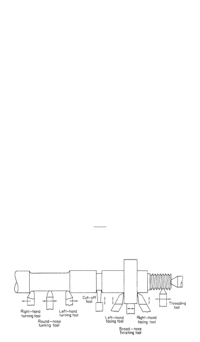
Fig. 9 Common lathe operations.
rocating tools or workpieces, feed is expressed in inches per stroke (ips) (mm/
stroke).
The recommended cutting speeds, and depth of cut that resulted from exten-
sive research, for different combinations of tools and materials under different
cutting conditions can be found in many references, including Society of Man-
ufacturing Engineers (SME) publications such as Tool and Manufacturing En-
gineers Handbook;
1
Machining Data Handbook;
2
Metcut Research Associates,
Inc.; Journal of Manufacturing Engineers; Manufacturing Engineering Trans-
actions; American Society for Metals (ASM) Handbook;
3
American Machinist’s
Handbook;
4
Machinery’s Handbook;
5
American Society of Mechanical Engi-
neering (ASME) publications; Society of Automotive Engineers (SAE)
Publications; and International Journal of Machine Tool Design and Research.
6 TURNING MACHINES
Turning is a machining process for generating external surfaces of revolution by
the action of a cutting tool on a rotating workpiece, usually held in a lathe.
Figure 9 shows some of the external operations that can be done on a lathe.
When the same action is applied to internal surfaces of revolution, the process
is termed boring. Operations that can be performed on a lathe are turning, facing,
drilling, reaming, boring, chamfering, taping, grinding, threading, tapping, and
knurling.
The primary factors involved in turning are speed, feed, depth of cut, and tool
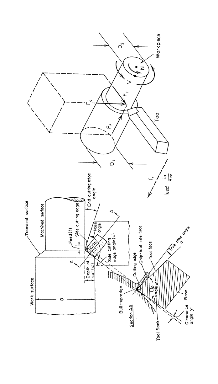
geometry. Figure 10 shows the tool geometry along with the feed (ƒ) and depth
of cut (d). The cutting speed (CS) is the surface speed in feet per minute (sfm)
or meters per sec (m/s). The feed (ƒ) is expressed in inches of tool advance per
revolution of the spindle (ipr) or (mm/rev). The depth of cut (d) is expressed
in inches. Table 5 gives some of the recommended speeds while using HSS tools
and carbides for the case of finishing and rough machining. The cutting speed
(fpm) is calculated by
DN
CS ⫽ fpm (30)
12
864
Fig. 10 Tool geometry—external turning.

6 TURNING MACHINES 865
Table 5 Typical Cutting Speeds ft / min (m /sec)
Material
High-Speed Steel
Finish
a
Rough
b
Carbide
Finish
a
Rough
b
Free cutting steels, 1112, 1315 250–350
(1.3–1.8)
80–160
(0.4–0.8)
600–750
(3.0–3.8)
350–500
(1.8–2.5)
Carbon steels, 1010, 1025 225–300
(1.1–1.5)
80–130
(0.4–0.6)
550–700
(2.8–3.5)
300–450
(1.5–2.3)
Medium steels, 1030, 1050 200–300
(1.0–1.5)
70–120
(0.4–0.6)
450–600
(2.3–3.0)
250–400
(1.3–2.0)
Nickel steels, 2330 200–300
(1.0–1.5)
70–110
(0.4–0.6)
425–550
(2.1–2.8)
225–350
(1.1–1.8)
Chromium nickel, 3120, 5140 150–200
(0.8–1.0)
60–80
(0.3–0.4)
325–425
(1.7–2.1)
175–300
(0.9–1.5)
Soft gray cast iron 120–150
(0.6–0.8)
80–100
(0.4–0.5)
350–450
(1.8–2.3)
200–300
(1.0–1.5)
Brass, normal 275–350
(1.4–1.8)
150–225
(0.8–1.1)
600–700
(3.0–3.5)
400–600
(2.0–3.0)
Aluminum 225–350
(1.1–1.8)
100–150
(0.5–0.8)
450–700
(2.3–3.5)
200–350
(1.0–1.8)
Plastics 300–500
(1.5–2.5)
100–200
(0.5–1.0)
400–650
(2.0–3.3)
150–300
(0.8–1.5)
a
Cut depth, 0.015–0.10 in. (0.38–2.54 mm); feed 0.005–0.015 ipr (0.13–0.38 mm / rev).
b
Cut depth, 0.20–0.40 in. (5.0–10.0 mm); feed, 0.030–0.060 ipr (0.75–1.5 mm /rev).
where D ⫽ workpiece diameter, in.
N
⫽ spindle revolutions per minute
For SI units,
DN
CS ⫽ m/s (31)
1000
where D is in mm
N is in revolutions per second
The tool advancing rate is F
⫽ ƒ ⫻ N ipm (mm/sec). The machining time
(T
1
) required to turn a workpiece of length L in. (mm) is calculated from
L
T ⫽ min (sec) (32)
1
F
The machining time (T
2
) required to face a workpiece of diameter D is given
by
D/2
T ⫽ min (sec) (33)
2
F
The rate of metal removal (MRR) (Q)isgivenby

866 PRODUCTION PROCESSES AND EQUIPMENT FOR METALS
3
Q ⫽ 12ƒdCS in. /min (34)
Power
⫽ QHP HP (35)
Power ⫽ Torque 2
N
Torque
⫻ N
⫽ HP (36)
63,025
where torque is in in.–lbf
For SI units,
Torque
⫻ N
Power ⫽ KW (37)
9549
where torque is in newton–meter and N in rev/min
torque
⫽ F
c
⫻ R
Torque
F ⫽ (38)
c
R
where R
⫽ radius of workpiece
To convert to SI units,
HP
⫻ 746 ⫽ ? Watt (W)
f (lb)
⫻ 4.448 ⫽ ? newtons
torque (in.–lb)
⫻ 0.11298 ⫽ ? newton–meter (Nm)
HP/(cu in./min)
⫻ 2.73 ⫽ ? W/(cu mm/sec)
ft/min
⫻ .00508 ⫽ ? m/sec
33
in. ⫻ 16,390 ⫽ ?mm
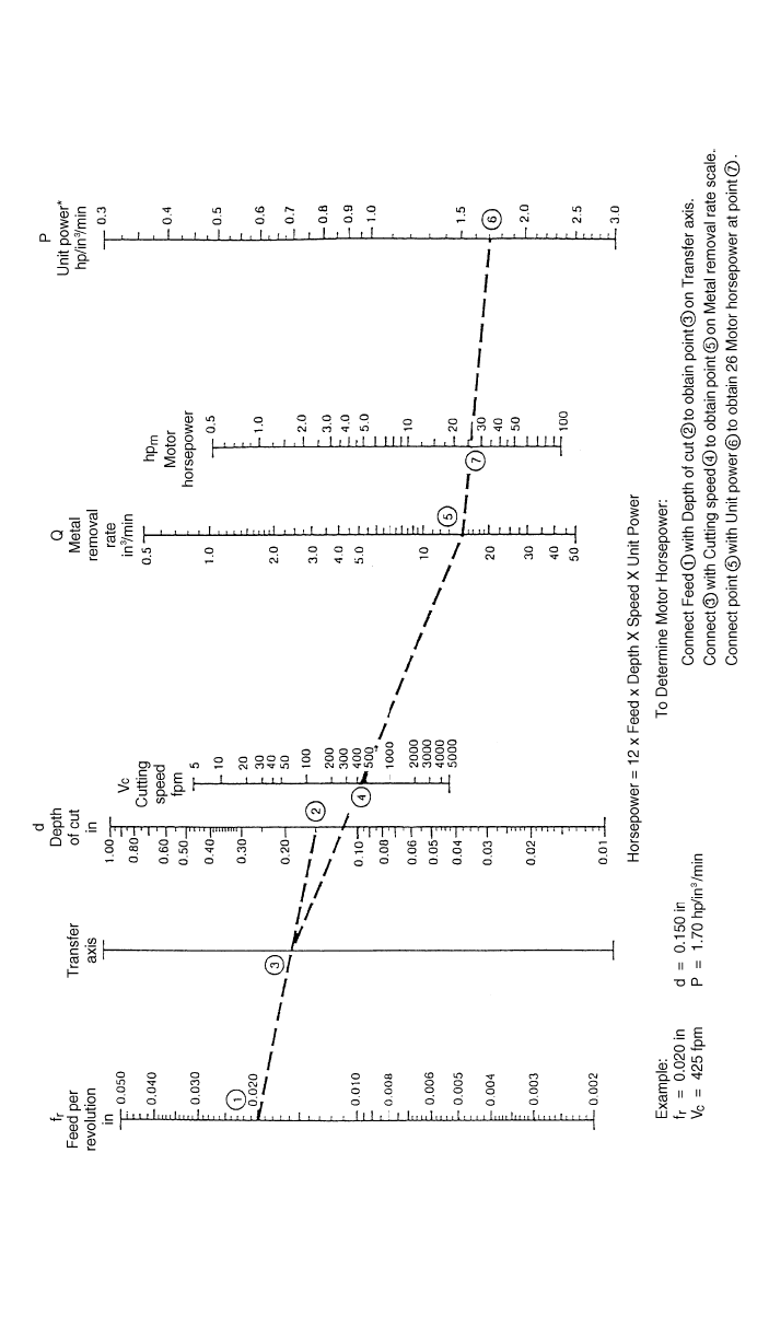
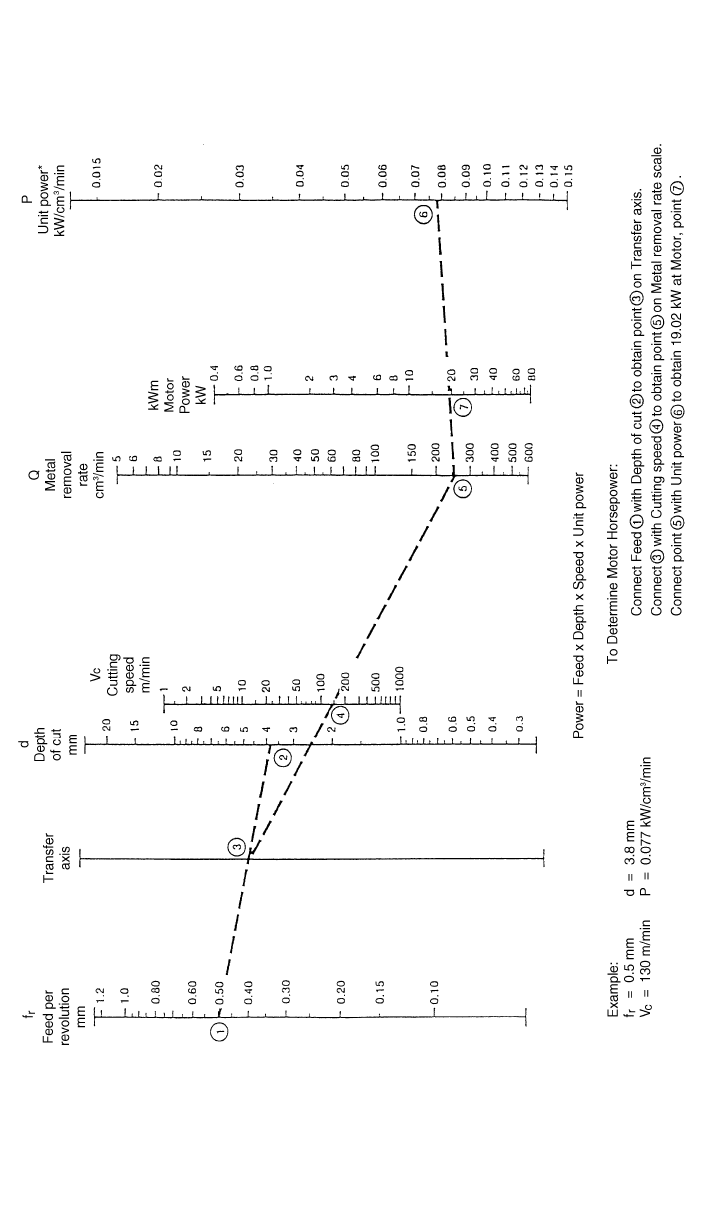
Alignment charts were developed for determining metal removal rate and motor
power in turning. Figures 11 and 12 show the method of using these charts
either for English or metric units. The unit power (P) is the adjusted unit power
with respect to turning conditions and machine efficiency.
6.1 Lathe Size
The size of a lathe is specified in terms of the diameter of the work it will swing
and the workpiece length it can accommodate. The main types of lathes are
engine, turret, single-spindle automatic, automatic screw machine, multispindle
automatic, multistation machines, boring, vertical, and tracer. The level of au-
tomation can range from semiautomatic to tape-controlled machining centers.
867
Fig. 11 Alignment chart for determining metal removal rate and motor horsepower in turning—English units.
868
Fig. 12 Alignment chart for determining metal removal rate and motor power in turning—metric units.
7 DRILLING MACHINES 869
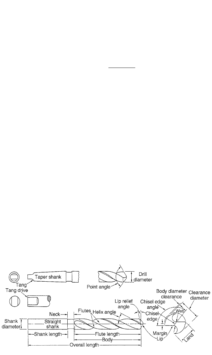
Fig. 13 Drill geometry.
6.2 Break-Even (BE) Conditions
The selection of a specific machine for the production of a required quantity q
must be done in a way to achieve minimum cost per unit produced. The incre-
mental setup cost is given by
⌬C
t
, C
1
is the machining cost per unit on the first
machine, and C
2
is the machining cost for the second machine, the break-even
point will be calculated as follows:
BE ⫽ ⌬C兹(C ⫺ C )
12
7 DRILLING MACHINES
Drills are used as the basic method of producing holes in a wide variety of
materials. Figure 13 indicates the nomenclature of a standard twist drill and its
comparison with a single-point tool. Knowledge of the thrust force and torque
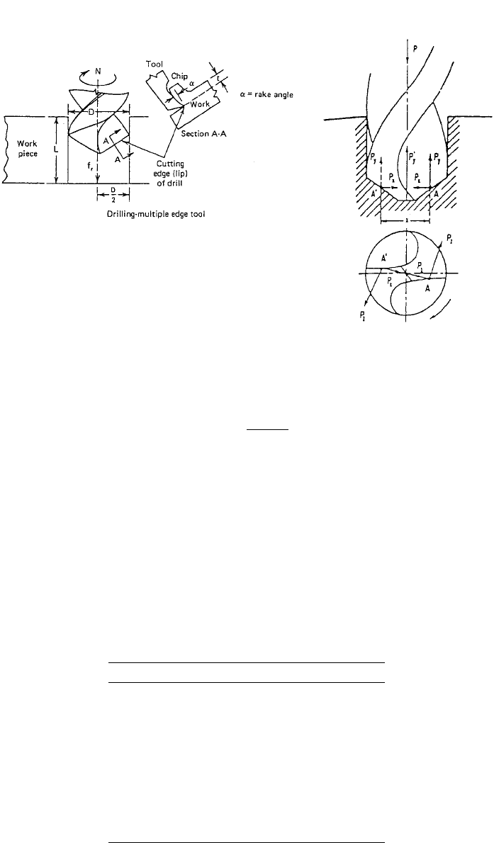
developed in the drilling process is important for design consideration. Figure
14 shows the forces developed during the drilling process. From the force dia-
gram, the thrust force must be greater than 2P
y
⫹ to include the friction on
1
P
y
the sides and to be able to penetrate in the metal. The torque required is equal
to P
2
X. It is reported in the Tool and Manufacturing Engineers Handbook
1
that
the following relations reasonably estimate the torque and thrust requirements
of sharp twist drills of various sizes and designs.
Torque:
0.8 1.8
M ⫽ KF d A in.–lbf (39)
Thrust:
0.8 0.8 2
T ⫽ 2Kƒ dB⫹ kd E lb (40)
The thrust force has a large effect upon the required strength, rigidity, and
accuracy, but the power required to feed the tool axially is very small.
870 PRODUCTION PROCESSES AND EQUIPMENT FOR METALS
Fig. 14 Thrust forces and torque in drilling operation.
Table 6 Work-Material Constants for Calculating
Torque and Thrust (National Twist Drill)
Work Material K
Steel, 200 Bhn 24,000
Steel, 300 Bhn 31,000
Steel, 400 Bhn 34,000
Most aluminum alloys 7,000
Most magnesium alloys 4,000
Most brasses 14,000
Leaded brass 7,000
Cast iron, 65 Bhn 15,000
Free-machining mild steel, resulfurized 18,000
Austenitic stainless steel (type 316) 34,000
Cutting power:
MN
HP ⫽ (41)
63,025
where K
⫽ work–material constant
ƒ
⫽ drill feed, ipr
d
⫽ drill diameter, in.
A, B, E
⫽ design constants
N
⫽ drill speed, rpm
Tables 6 and 7 give the constants used with the previous equations. Cutting
speed at the surface is usually taken as 80% of turning speeds and is given by

7 DRILLING MACHINES 871
Table 7 Torque and Thrust Constants Based on Ratios c / d or w /d
(National Twist Drill)
c / dw/d
Torque Constant
A
Thrust Constant
B
Thrust Constant
E
0.03 0.025 1.000 1.100 0.001
0.05 0.045 1.005 1.140 0.003
0.08 0.070 1.015 1.200 0.006
0.10 0.085 1.020 1.235 0.010
0.13 0.110 1.040 1.270 0.017
0.15 0.130 1.080 1.310 0.022
0.18 0.155 1.085 1.355 0.030
0.20 0.175 1.105 1.380 0.040
0.25 0.220 1.155 1.445 0.065
0.30 0.260 1.235 1.500 0.090
0.35 0.300 1.310 1.575 0.120
0.40 0.350 1.395 1.620 0.160
dN
CS ⫽ fpm
12
Force in cutting direction:
33,000 HP
F ⫽ lb (42)
c
CS
For SI units,
dN
1
CS ⫽ m/sec (43)
60,000
c
⫽ chisel-edge length, in.
d
⫽ drill diameter, in.
w
⫽ web thickness, in.
d
⫽ drill diameter, in mm
1
33
Unit HP (hp/in. /min) ⫻ 2.73 ⫽ ? unit power (kW/cm /s)
MN
kW ⫽ (44)
9549
M
⫽ torque Nm
For drills of regular proportion the ratio c/d is
⫽ 0.18 and c ⫽ 1.15 w, approx-
imately.
It is a common practice to feed drills at a rate that is proportional to the drill
diameter in accordance with

872 PRODUCTION PROCESSES AND EQUIPMENT FOR METALS
Table 8 Recommended Feeds for Drills
Diameter
(in.) (mm)
Feed
(ipr) (mm / rev)
Under
1
⁄
8
3.2 0.001–0.002 0.03–0.05
1
⁄
3
–
1
⁄
4
3.2–6.4 0.002–0.004 0.05–0.10
1
⁄
4
–
1
⁄
2
6.4–12.7 0.004–0.007 0.10–0.18
1
⁄
2
–1 12.7–25.4 0.007–0.015 0.18–0.38
Over 1 25.4 0.015–0.025 0.38–0.64
d
ƒ ⫽ (45)
65
For holes that are longer than 3d, feed should be reduced. Also feeds and speeds
should be adjusted due to differences in relative chip volume, material structure,
cutting fluid effectiveness, depth of hole, and conditions of drill and machine.
The advancing rate is
F
⫽ ƒ ⫻ N ipm (46)
The recommended feeds are given in Table 8.
The time T required to drill a hole of depth h is given by
h
⫹ 0.3d
T ⫽ min (47)
F
The extra distance of 0.3d is approximately equal to the distance from the tip
to the effective diameter of the tool. The rate of metal removal in case of blind
holes is given by
2
d
3
Q ⫽ F in. /min (48)
冉冊
4
When torque is unknown, the horsepower requirement can be calculated by
HP
⫽ Q ⫻ C ⫻ W ⫻ (HP )hp
c
C, W, HP
are given in previous sections.
Power
⫽ HP ⫻ 396,000 in.–lb/min (49)
c
Power
Torque ⫽ in–lbf
2
N
Torque
F ⫽ lb
c
R
Along the cutting edge of the drill, the cutting speed is reduced toward the center
