Kounadis A.N., Gdoutos E.E. (Eds.) Recent Advances in Mechanics
Подождите немного. Документ загружается.


Experimental Mechanics in Nano-engineering 289
Table 3, on the basis of the expected aspect ratios, gives the theoretical
dimensions of the sides of the nano-crystals and compares them with the measured
values. Results of statistical analysis of probable errors in measurements are also
presented in the table. A conservative assumption to estimate the accuracy of the
measurements was made by adopting the smallest dimensions of the crystals as
given quantities from which the other dimensions are then estimated. The smallest
dimensions are the ones that will have the larger absolute errors.
Table 3. Main dimensions of the observed nano-crystals: experiments vs. theory
Nano-crystal
length (nm)
Dimensions
Measured
Dimensions
Theoretical
Difference
(nm)
72 66.3 +5.7
54 54 53 +1
53 53 -----
55 55.8 -0.8
55 45 55.8 -10.8
33.5 33.5 -----
104 107.5 -3.5
86 86 86 0
86 86 -----
120 122.7 -2.7
120 46 46 0
46 46 -----
Mean absolute error = 3.06 nm; Mean error = -1.39 nm.
Standard deviation of absolute error = ± 3.69 nm.
2.4 Analysis of the Polystyrene Nano-spheres
A similar analysis can also be performed for the resonant modes of polystyrene
nano-spheres injected in the saline solution. Micro-spheres and nano-spheres made
of transparent dielectric media are excellent optical resonators. Unlike the NaCl
nano-crystals whose resonant modes have not been previously studied in the
literature, both theoretical and experimental studies on the resonant modes of
micro-spheres and nano-spheres can be found in the literature. Among the
resonance modes of these spheres, of particular interest are the modes localized at
the surface, along a thin equatorial ring. These modes are called whispering-
gallery modes (WGM). The WG modes are within the Mie’s family of solutions
for resonant modes in light scattering by dielectric spheres. The WG modes can be
also derived from Maxwell's equations by imposing adequate boundary
conditions. They can also be obtained as solutions of the Quantum Mechanics
Schrodinger-like equation that describes the evolution of a complex angular-
momentum of a particle in a potential well.
290 C.A. Sciammarella, F.M. Sciammarella, and L. Lamberti
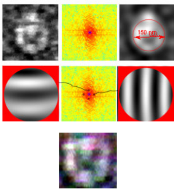
Figure 9 shows the image of a spherical particle of diameter 150 nm. This
image presents the typical whispering gallery intensity distribution. Waves are
propagating around the diameter in opposite directions thus producing a standing
wave with 7 nodes and 6 maxima. The light is trapped inside the particle and there
is basically a surface wave that only penetrates a small amount into the radial
direction. The signal recorded for this particle is noisier compared with the signal
recorded for the prismatic crystals. The noise increase is probably due to the
Brownian motion of the spherical particles. While the NaCl nano-crystals seem to
grow attached the supporting surface, the nano-spheres are not in the same
condition. Of all resonant geometries a sphere has the capability of storing and
confining energy in a small volume.
Fig. 9. Spherical nano-particle of estimated diameter 150 nm: a) Gray-level image of the
particle, FT pattern and 0-order filtered pattern; b) Systems of fringes modulated by the
particle; c) Color image of the particle.
The method of depth determination utilized for the nano-crystals can be applied
also to the nano-spheres. While in prismatic bodies made out of plane surfaces the
pattern interpretation is straightforward, in the case of curved surfaces the analysis
of the patterns is more complex since light beams experience changes in
trajectories determined by the laws of refraction. In the case of a sphere, the
analysis of the patterns can be performed in a way similar to what is done in the
analysis of the Ronchi test for lens aberrations. Figure 9 shows the distortion of a
grating of pitch p=83.4 nm as it goes through a nano-sphere of estimated diameter,
on the base of the edge light gradient method, D
e
=150 nm. The appearance of the
observed fringes is similar to that observed in a Ronchi test. The detailed
description of this process is not included in this chapter for the sake of brevity.
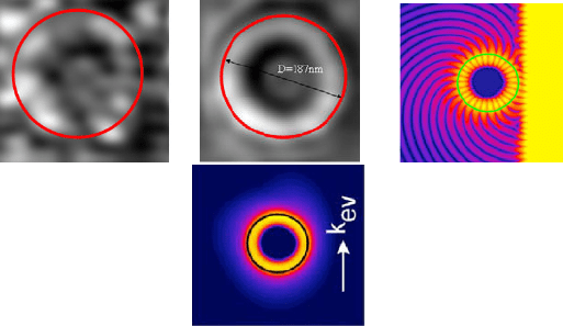
Figure 10 shows another spherical particle of diameter 187 nm while Fig. 10b
shows the average intensity. Figure 10c is extracted from Ref. [20] and shows the
a
)
b
)
c
)
Experimental Mechanics in Nano-engineering 291
numerical solution for the WGM of a polystyrene sphere of diameter 1.4 μm while
Fig. 10d shows the average intensity.
a) b) c)
d)
Fig. 10. Spherical nano-particle of estimated diameter 187 nm: experimentally recorded
images and numerical simulations. a) Original image; b) Average intensity image; c)
Numerical simulation of whispering modes; d) Average intensity of numerical simulation.
It is possible to see the correspondence between experimental results and
numerical simulations. The electromagnetic resonance occurs at the wavelength
λ=386 nm which corresponds to UV radiation. The color camera is sensitive to
this frequency and Fig. 9c shows the color picture of the D
e
=150 nm nano-sphere:
the observed color corresponds approximately to the above mentioned resonance
wavelength.
3 Application of Surface Plasmon Resonance to Surface
Roughness Topography
The previous examples illustrated the utilization of evanescent waves in the
analysis of nano-size dielectric objects. The next application to be described is the
utilization of evanescent waves to study the topography and deformation of
surfaces. In the case of the nano-objects the interaction of the evanescent waves
with the objects takes place by resonance phenomena with bound electrons. When
a plane wave front impinges the surface separating two media such that the index
of refraction of medium 1, glass, is higher than the index of refraction of medium
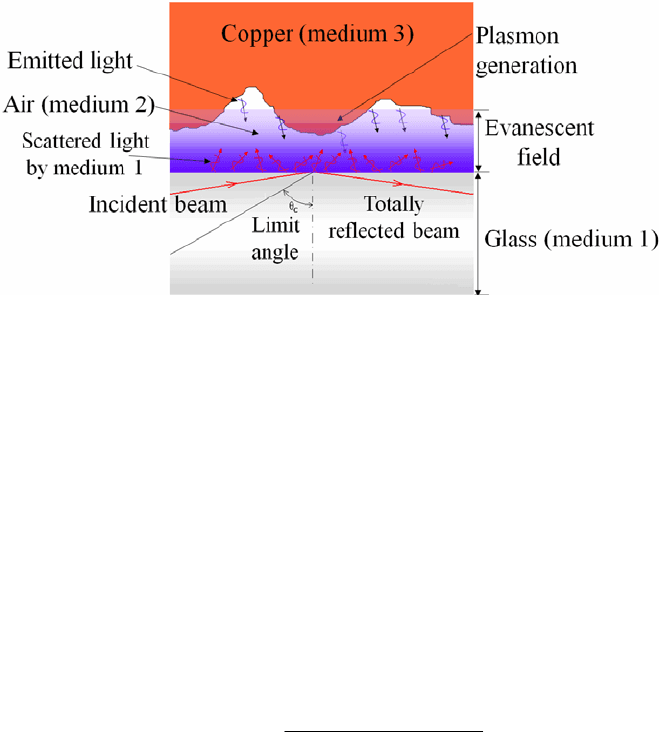
2, air, at the limit angle total reflection takes place (see Fig. 1). Under these
circumstances a very interesting phenomenon occurs. At the interface (glass-air)
evanescent waves are produced. At the same time, scattered waves emanate from
the medium 1 (glass). If a third medium, a conducting material, for example a
metal, is close enough to interact with this field the energy from this field interacts
with the metal’s surface free electrons to generate plasmons (dark orange area in
Fig. 11) that by decaying cause the metal surface to emit light.
292 C.A. Sciammarella, F.M. Sciammarella, and L. Lamberti
Fig. 11. Generation of the evanescent field and surface plasmon resonance in the cavity
between a glass plate and a rough copper surface.
Between the copper and the glass surface there is an optical cavity or optical
resonator that produces standing waves. The electromagnetic field confined in the
cavity is reflected multiple times inside the cavity producing standing waves for
certain resonance frequencies that depend on the geometry of cavity. The standing
wave patterns thus generated are called modes: each mode is characterized by a
frequency f
n
, where the subscript n is an integer. Optical cavities are characterized
by the quality factor, or Q factor. The Q factor is a dimensionless parameter that
defines the resonator's bandwidth relatively to its center frequency. Low values of
Q indicate high losses of energy in the cavity and a wide bandwidth. High values
of Q indicate a low rate of energy loss in the cavity with respect to the stored
energy of the oscillator and a narrow bandwidth. In general, Q is defined in terms
of the ratio of the energy stored in the resonator to the energy being lost in one
cycle:
cycleperlossEnergy
StoredEnergy
Q
π2= (19)
It can be proven that the maximum energy is concentrated in the direction of the
normal to the face of the glass medium.
3.1 Generation of a Wide Spectrum of Frequencies due to Interaction
between Evanescent Waves and Rough Surfaces
In the classical Fabry-Perot cavity analysis the two interacting surfaces are mirror-
like surfaces. In the present case one of the surfaces is a mirror-like surface (the
glass) while the other (the metal) is an optically rough surface. Therefore, many
different spatial frequencies can be observed experimentally. At this point it is
important to describe the phenomenon leading to the generation of the emitted
light with different spatial frequencies on rough metallic surfaces. A rough surface
can be thought of as the superposition of many gratings of different periodicities.

Experimental Mechanics in Nano-engineering 293
Kretschmann analyzed this problem in the following fashion [21]. A rough surface
can be defined through the following statistical correlation function:
∫
−−=
A
'dy'dx)y'y,x'x(z)'y,'x(z
A
1
)y,x(G
(20)
where z(x,y) is the Monge’s representation of the surface height and A is the area
of integration.
Under the assumption that the height distribution is a random function, as it is
usually done in the analysis of random surfaces, a Gaussian distribution can be
utilized. The correlation function becomes:
⎟
⎟
⎠
⎞
⎜
⎜
⎝
⎛
σ
−=
2
i
2
2
q
r
expR)y,x(G
(21)
where:
2
q
R is the root-mean-square value of the surface heights assumed to be
random variables with a correlation length σ
ι
; r is the distance from the generic
point P(x,y) of the object surface.
From the Fourier transform (FT) of Eq. (21) the spectrum s of spatial
frequencies present in the surface can be obtained.
From the point of view of plasmon excitation, one can prove that in order to
excite a plasmon resonance it is necessary that the exciting frequency coincides
with a frequency in the Fermi’s electromagnetic state. Hence, the larger is the
spectrum of the frequencies the greater will be the amount of energy available for
producing coupling of plasmons within the metallic surface. The spatial frequency
spectrum is described by the following equation:
()
⎥
⎥
⎦
⎤
⎢
⎢
⎣
⎡
σ
−σ
π
=
4
k
expR
4
1
ks
2
surf
2
i
2
q
2
i
surf
(22)
The above equation shows that the spectrum of light emitted by the surface
consists of multiple wave vectors that are related directly with surface topography
properties. Each wave vector corresponds to an equivalent pitch p
gr
defined as:
.
gr
surf
p
2
k
π
= (23)
If the surface has only one Fourier component of roughness (i.e. the surface
profile is sinusoidal), then the s function is discrete and exists only at
gr
surf
p/2k π= where p
gr
is the pitch of the equivalent sinusoidal grating.
However, most surfaces of practical interest have a definite structure and cannot
be considered random surfaces. Surfaces of technical interests manufactured
industrially present a periodic structure. For this reason finished surfaces are more
similar to a deterministic diffraction grating than to a random grating.
294 C.A. Sciammarella, F.M. Sciammarella, and L. Lamberti
Any plasmon propagating on a rough surface with the appropriate k
surf
can
generate the emission of a photon [22]. Since k
surf
can be a random quantity, even
if the light has a defined direction it is possible to generate plasmons in all
directions. This phenomenon was verified experimentally by Teng and Stern [23].
3.2 Application of the Model to the Analysis of Surface Topography
The above model gives an explanation of the interaction of evanescent waves at a
glass-air-metal interface. This explanation has provided insight into how it is
possible to make the experimental observations due to the ability of evanescent
illumination to interact with the metal surface creating plasmons that upon decay
can emit light. Since the experimental setup has a double interface (glass-air and
air-metal) a cavity is created: this cavity acts as a passive optical resonator and
hence resonances can be observed from the emitted light.
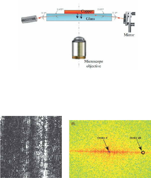
Fig. 12. Experimental setup for the SPR analysis of metallic specimens.
The original setup utilized to perform surface topography measurements on
metallic specimens [24] is shown in Fig. 12. An incident laser beam is totally
reflected at the glass-air interface and returned by the mirror shown in the figure.
The metal-air-glass interface is observed with an optical microscope and an image
is recorded by a CCD camera.
a) b)
Fig. 13. a) Enlarged portion of the image of the copper plate surface; interference fringes on
the metal surface are clearly visible; b) FT of the image (225 x 225 μm).
θ
i
Experimental Mechanics in Nano-engineering 295
Figure 13a shows the recorded image of the copper surface. A system of fringes
can be seen in this image. This system of fringes is localized on the surface since
the focused image captures the surface features as well as the fringes. The spatial
frequency of the fringes (pitch) can be determined by analyzing the FT of the
image (see Fig. 13b). In the FT it is possible to identify the fundamental harmonic
corresponding to the fringe’s image. From the analysis of the fringes it was
concluded that the fundamental harmonic has a pitch of 4.69 microns.
The wave vector of the emitted field corresponds to a spatial frequency of order
48 that, translated to fringe spacing in the physical space, gives a value of 4.69 μm
(i.e. from the size of the region of 225 microns, one obtains 225/48=4.69 μm). In
Ref. [24], it was proven that the diffracted order of the equivalent grating resulting
from the electromagnetic resonance is:
i
egr
sin2
p
θ
λ
=
(24)
where θ
i
is the angle made by the illumination beam with the glass surface (see
Fig. 12).
By entering p
egr
=4.69 μm into Eq. (24), a value of θ
i
=3.87
o
is obtained. This
result is in very good agreement with the initial experimentally set value of 3.9
o
.
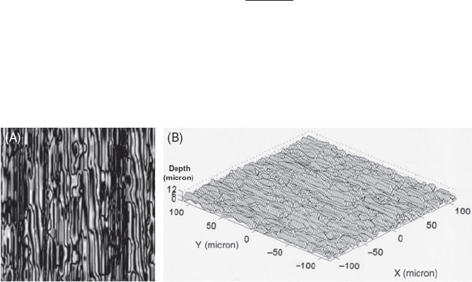
Fig. 14. a) Top view of the depth information in gray levels of a region of 225x225 μm; b)
3-D view of the same region (the same scale for all the 3 coordinates was taken).
Figure 14 shows the surface profile obtained from the fringe pattern of Fig. 13.
In Ref. [24], it is shown that the model of the process to convert fringe pattern into
topographic data is exactly the same that corresponds to reflection moiré when the
grating is in the vicinity of the surface and the observation is made by focusing the
plane of the grating. This model was originally analyzed by Ebbeni [25] by
utilizing the Fresnel-Kirchhoff integral for the grating-based contouring of very
large curvature radii reflecting surfaces. Sciammarella and Combel [26] also
analyzed this problem. While in [25] only the first harmonic was considered, in
[26] following the method introduced by Guild [27], all the harmonics that emerge
with the same angle of inclination were considered thus obtaining multiple
interference fringes.

296 C.A. Sciammarella, F.M. Sciammarella, and L. Lamberti
The profile of the surface in terms of the surface depth h can be obtained from
the equation:
)90sin(2
np
h
i
o
0gr
θ−
=
(25)
where n is the fringe order corresponding to the fact that an equivalent grating of
pitch p
gr0
is modulated by the surface. This relationship is similar to the equation
of shadow-projection moiré except for the factor 2 that comes from the reflection
effect.
In order to verify the reliability of the experimental data gathered with the
above described model, other independent measurements were carried out with a
Surtronic S25 profilometer (Taylor Hobson Ltd.). The ten-point height of the
surface S
z
was chosen as the reference parameter [28,29]. Ten transversal sections
(i.e. in the direction orthogonal to grooves) and ten longitudinal sections (i.e., in
the direction of the furrows present in the surface) were analyzed and the
corresponding ten-point heights were computed. For the profilometer
measurements, two sections of length 8 mm were analyzed both in the
longitudinal (i.e. parallel to the furrows) and transversal direction (i.e.,
perpendicular to the furrows). Optical and mechanical measurements were in good
agreement. The test of significance for small samples revealed that both optical
and mechanical data belong to the same statistical population within 95% level of
confidence.
In the second set of experimental tests, gratings of different pitches were
utilized in order to obtain the surface topography of standard samples. The values
of the roughness average parameter R
a
were determined [28,29]. Surface
roughness measurements carried out for the different calibrated samples were
again in good agreement with profilometer measurements.
3.3 High Accuracy Measurements of Surface Topography
In order to determine the accuracy of the method of surface contouring outlined in
Section 3.2, measurements of the roughness were carried out on an HQC226
precision reference standard certified by NIST according to ANSI B46.1. Figure 15
shows a schematic of the experimental setup. Some modifications have been
introduced with respect to the original setup of Fig. 12. A grating has been added to
the surface of the glass plate. In this way it is possible to obtain more than one
fundamental frequency by utilizing the different frequencies produced by the
grating.
The previous picture shows the interface between the glass surface and the
metallic surface. The surface consists of a saw tooth profile of nominal pitch
L
t
=100 μm and depth h
t
=6 μm. The resultant R
a
(average depth) is 3 μm. This
standard is used to calibrate devices based on the use of stylus probes.
Figure 15 provides a model for the process of contouring that can be also
applied to other surfaces that are not deterministic. The figure illustrates the case
of double illumination but only one illumination beam is analyzed here for the
sake of simplicity.
Experimental Mechanics in Nano-engineering 297
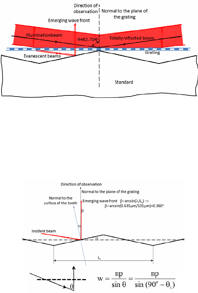
Fig. 15. Experimental setup for surface topography analysis including a grating.
The inclination of the beam is larger than the critical angle and therefore the
light is totally reflected at the glass-air interface. However, as it was indicated
previously, the electromagnetic field penetrates a cavity. Schematically, the figure
shows the trajectory of the photons that enter the cavity and, according to the
preservation of momentum, continue their trajectory. Photons finally emerge
along the direction approximately perpendicular to the grating surface as it is
clarified by the detailed schematic of Fig. 16.
Fig. 16. Detail of the optical path of the beams diffracted by the grating (a) and equivalent
shadow/projection moiré scheme (b).
a)
b)
298 C.A. Sciammarella, F.M. Sciammarella, and L. Lamberti
Figure 16 is a schematic representation to explain the contouring model
although from the theoretical point of view of optics the process is very
complicated. The figure shows the beam arriving at the inclination θ
i
with respect
to the standard surface which is now described as a blazed diffraction grating.
According to the equation of diffraction for a blazed grating, the angle of
emergence β with respect to the normal to the middle surface of the grating is:
⎟
⎟
⎠
⎞
⎜
⎜
⎝
⎛
λ
=β
t
L
arcsin
(26)
In this particular case, the wavelength of light λ is 635 nm and the spacing of the
grating is L
t
=101 μm (i.e. the saw tooth pitch). By replacing this value in Eq. (26),
the angle β of the emerging wave front is 0.360
o
. Hence, the beam emerges
practically orthogonal to the grating surface.
As is shown in Fig. 16, one can now apply the classical shadow-projection
moiré equation:
)90(sin
np
sin
np
w
i
o
θ−
=
θ
=
(27)
This is in agreement with the formulation developed in Ref. [24].
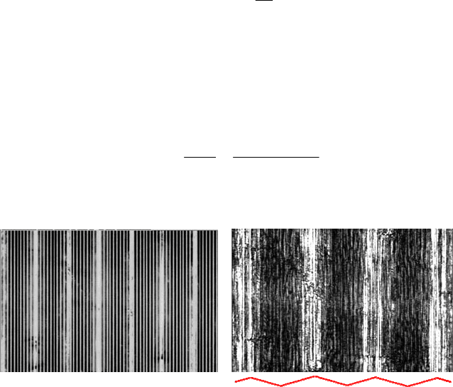
a) b)
Fig. 17. a) White light image of the HQC226 standard (5 μm grating superimposed on the
specimen); b) Coherent illumination image (5 μm grating superimposed on the standard).
The profile of the standard is sketched in red in Fig. 17b.
Figure 17 shows the image of the standard with the superimposed 5 μm pitch
grating. Figure 17a corresponds to white light while Fig. 17b corresponds to
coherent illumination. It is interesting to point out that, while the white light
illumination that is normal to the plane of the grating shows peaks and valleys, the
evanescent illumination creates the higher intensity in the region of contact with
the grating since the evanescent field dies out within a fraction of the wavelength
of light. By measuring the horizontal size (i.e. in the direction normal to fringes)
of the bright region, the value of 11.81 μm is obtained. This means that the local
depth at the end of the bright region is 11.81*tan[h
t
/(L
t
/2)], that gives 1.42 μm.
