Kounadis A.N., Gdoutos E.E. (Eds.) Recent Advances in Mechanics
Подождите немного. Документ загружается.

Recent Advances in Microelectromechanical
Systems and Their Applications for Future
Challenges
Ryszard J. Pryputniewicz
NEST – NanoEngineering, Science, and Technology
CHSLT – Center for Holographic Studies and Laser micro-mechaTronics
Mechanical Engineering Department
Professor of Electrical and Computer Engineering
Worcester Polytechnic Institute
Worcester, MA 01609 USA
Tel.: (508) 831-5536; Fax: (508) 831-5713
rjp@wpi.edu
Abstract. Recent advances in optoelectronic methodology for microscale
measurements are described and their use is illustrated with representative examples
of microelectromechanical systems (MEMS) operating at high frequencies and used
in demanding environments. Today, the word MEMS is employed to describe a
process used as well as the resulting products. Therefore, a MEMS-process is also
known as a “microsystem technology” (MST).
Advances in emerging technologies (ETs) of MEMS and nanotechnology,
especially relating to the applications, constitute one of the most challenging tasks
in today’s micromechanics and nanomechanics. In addition to design, analysis,
and fabrication capabilities, these tasks also require advanced test methodologies
for determination of functional characteristics of devices produced to enable
verification of their operation as well as refinement and optimization of specific
designs. In particular, development of miniscule devices requires sophisticated
design, analysis, fabrication, testing, and characterization tools. These tools can
be categorized as analytical, computational, and experimental. Solutions using the
tools from any one category alone do not usually provide necessary information
on MEMS and extensive merging, or hybridization, of the tools from different
categories is used. One of the approaches employed in this development of
structures of contemporary interest, is based on a combined use of the analytical,
computational, and experimental solutions (ACES) methodology. Development
of this methodology was made possible by recent advances in optoelectronic
methodology, which was coupled with the state-of-the-art computational methods,
to offer a considerable promise for effective development of various designs.
This approach facilitates characterization of dynamic and thermomechanical
behavior of the individual components, their packages, and other complex material
250 R.J. Pryputniewicz
structures. In this paper, recent advances in optoelectronic methodology for
micro- and nano-scale measurements are described and their use is illustrated with
representative examples.
Keywords: MST, emerging technologies, optoelectronic methodology, operating
conditions, quantitative measurements, performance characteristics, reliability.
1 Introduction
Continued advances of contemporary microcomponents have made them
ubiquitous. Today, these components are used in multitude of applications
ranging from everyday (automotive and household appliances) through national
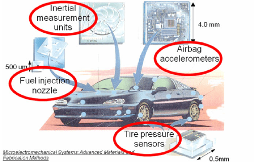
security to space exploration. For example, Fig.1 illustrates some of the devices
used in automobiles for fuel injecton, tire pressure sensors, inertial measurement
units (IMUs), and airbag deployment.
Fig. 1. Some of the microsensors used in automotive applications.
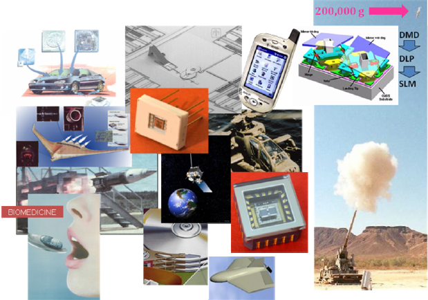
These automotive as well as a number of other present-day applications of the
microcomponents, and structures they enable, are summarized in Fig. 2 illustrating
numerous and much diversified functions, which require sophisticated design,
analysis, fabrication, testing, and characterization tools [1-3]. These tools can be
categorized as analytical, computational, and experimental [4]. Solutions using the
tools from any one category alone do not usually provide necessary information on
the components being developed and, as a result, extensive merging, or
hybridization, of the tools from different categories is used [5-7]. One of the
approaches employed in the development of microcomponents, as well as other
complex structures of current interest, is based on a combined use of analytical,
computational, and experimental solutions (ACES) methodology [4, 8-10].
Recent Advances in Microelectromechanical Systems and Their Applications 251
Fig. 2. Representative applications of present-day MEMS.
In general, analytical tools are based on exact, closed form solutions. These
solutions, however, are usually applicable to simple geometries for which, boundary,
initial, and loading (BIL) conditions can be readily specified. However, analytical
solutions are indispensable to gain insight for overall representation of the ranges of
anticipated results. They also facilitate determination of “goodness” of the results
based on uncertainty analysis [11]. Computational tools, i.e., finite element methods
(FEMs), boundary element methods (BEMs), and finite difference methods (FDMs),
provide approximate solutions as they discretize the domain of interest and the
governing partial differential equations (PDEs). The characteristics of discretization,
in conjunction with the BIL conditions, influence degree of approximation and
careful convergence studies should be performed to establish correct computational
solutions and modelling [12]. It should be noted that both analytical and
computational solutions depend on material properties. If material properties are
well known, then solutions typically give correct results, providing convergence was
achieved subject to properly specified BIL conditions; if material properties are not
sufficiently known, in spite of having a good knowledge of other modelling
parameters, erroneous results may be obtained [10]. Experimental tools, however,
in contrast to analytical and computational tools, evaluate actual objects, subjected
to actual/realistic operating conditions (including BIL conditions), and provide
ultimate results characterizing objects being investigated.
Until recently, this characterization was hindered by lack of a readily available
methodology suitable for use in the development of emerging technologies (ETs).
252 R.J. Pryputniewicz
However, building on recent advances in photonics, electronics, and computer
technology, a novel optoelectronic methodology particularly suitable for
quantitative studies of microsystems was developed [13]. This methodology
remotely and noninvasively evaluates the systems of interest and produces full-
field-of-view results with very high spatial resolution and nanometer accuracy in
near real-time; it also facilitates generation of animations of experimental results
which display time-dependent 3D deformation fields due to thermal and/or
mechanical/dynamic loads to which the components are subjected during a given
characterization/measurement.
Implementation of the optoelectronic methodology for development of ETs, as
presented in this paper, is based on the use of samples described in Section 2.
2 Representative MEMS Samples
The following representative MEMS samples are used in this paper: 1) high
rotational speed (HRS) microengine, 2) microgyroscope, 3) pressure sensor, and
4) cantilever-type Ohmic-contact for a microswitch.
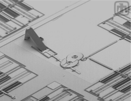
The electrostatically driven HRS microengine, developed at Sandia National
Laboratories (SNL) to operate at 1,000,000 revolutions per minute (rpm), was
used, in one of its applications, to actuate micromirror devices [14], Fig. 3.
Fig. 3. Sandia micromirror device actuated by electrostatically driven HRS microengine.
The microgyroscope (aka MEMS gyroscope, or microgyro) sensor is a
Coriolis-force electrostatic comb driven, tuning fork (i.e., differential pair) design
[15] and is a fundamental microcomponent for development of inertial
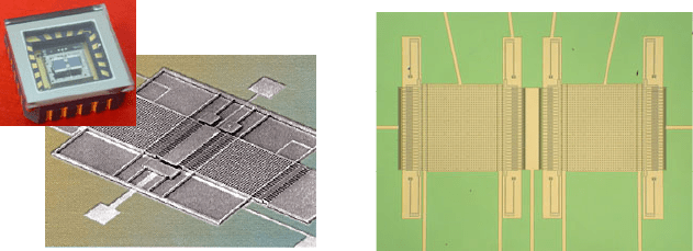
measurement units (IMUs). In the configuration shown in Fig. 4, used in this
study, a microgyro is actuated by electrostatic comb drives. The comb drives, in
Recent Advances in Microelectromechanical Systems and Their Applications 253
turn, are excited in such a way that the electrostatic forces they generate depend
on lateral position(s) of the proof masses (i.e., shuttles). The resulting (large)
amplitude vibrations/oscillations, parallel to teeth of the comb drives, increase
sensitivity of a microgyro and reduce errors from external forces. Angular rate,
with respect to the axis located in the plane of the shuttles, lifts one mass up and
lowers the other mass down due to the Coriolis forces. Capacitors, usually located
below the shuttles, accurately sense these up and/or down motions. The shuttles
are mounted/attached to the substrate through suspension springs, Fig. 5. The
mode of operation where the shuttles move in opposite directions lowers
sensitivity of a microgyro to linear acceleration. The two vibrating shuttles,
suspended by folded springs, are driven by electrostatic comb drives to maintain
lateral in-plane oscillation.
Fig. 4. Typical microgyro package (top left)
and a representative inertial MEMS sensor
(in the background).
Fig. 5. Close-up of the shuttles and folded
suspension springs, one spring is used in
each of 4 corners of every proof mass/
shuttle.
A MEMS pressure sensor, Fig. 6, utilizing polysilicon sensing technology, can
provide high performance, long-term stability, and low overall cost of installation
and operation [16]. In addition, safety and environmental concerns can increase
the benefits of this sensor by reducing the potential of fugitive emissions through
fewer process penetrations. This unique polysilicon piezoresistive sensor (PPS)
measures differential pressure (DP), absolute pressure (AP), and temperature (T)
on a single chip.
The PPS technology differs significantly from conventional single crystal
technology in that it employs dielectric isolation, which allows consistent
deposition of the polysilicon sensing diaphragms to a specific controllable
thickness, and facilitates placement of multiple sensing diaphragms on a single
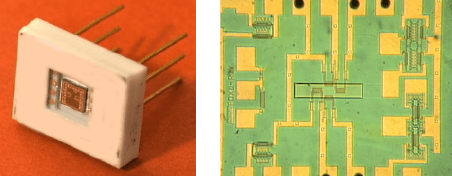
chip, Fig. 7. The diaphragm, which senses the applied DP, is shown in the center
of the chip; it is some 160 µm wide, 650 µm long, its multilayer/multimaterial
thickness is about 2 µm, and the cavity (providing overpressure protection) under
the diaphragm is 0.9 µm deep.
254 R.J. Pryputniewicz
Fig. 6. MEMS multivariable PPS package.
Fig. 7. MEMS multivariable PPS that measures
DP, AP and T on a single sensing chip.
Deformations of a diaphragm are sensed by four piezoresistive bridge elements
that are 0.4 µm thick and are electrically connected into the Wheatstone bridge
configuration. Determination of pressure from strains of the piezoresistors is
based on computations relying on a number of material specific and process
dependent coefficients that certainly can vary, which may lead to uncertainties in
displayed results. To establish an independent means for measurements by the
PPS diaphragms and to validate the coefficients used, we have developed a hybrid
methodology [17] for measurements and characterization of MEMS pressure
sensors.
The microswitch considered in this paper is a cantilever-type radio frequency
(RF) MEMS switch [18], Fig. 8. The figure shows a microcantilever-type contact
of active length L fabricated parallel to a substrate in such a way that separation
between the electrodes (one electrode is on a microcantilever and the other is
directly below on top of a substrate) is d
e
; for stable operation of a microswitch d
e
should be at least 3 times greater than the contact gap distance d
g
. During
functional operation, voltage applied to the electrodes induces an electrostatic
force that activates/actuates a microswitch [19]. The electrostatic force bends a
microcantilever causing the contacts to touch (i.e., by reducing the gap distance,
d
g
, to zero), which closes an electrical path (by making a cross bar to bridge/close
an “opening”, defined by L
to
in Fig. 8, in a trace usually located below the free end
of a microcantilever) and facilitates propagation of an electrical signal. As the
activation/actuation voltage is released, elasticity of the microcantilever is used to
return it to its original, or open, position (i.e., making d
g
>0). Mechanically, the
microcantilever of a switch behaves like a conventional cantilever [20]. In fact,
traditional equations can be used to find microcantilever stiffness, natural
frequency, pull-in voltage, and magnitude of the activation/actuation force. The
switch fabrication methods are particularly important because they dictate the
material type, surface finish, texture, and overall size of the microswitch
components (especially electrical interfaces of a microswitch). Consequently,
material properties have a direct influence on thermal management characteristics
of a microswitch and its behavior under actual operating conditions [18]. In fact,

Recent Advances in Microelectromechanical Systems and Their Applications 255
fabrication tolerances and accuracy of material properties have profound influence
on dynamics as well as the thermomechanical performance of microswitches
[18,21].
CANTILEVER
ELE CTRODES
d
L L
d
b
s
o
e
oe
h
h
d
h
s
t
L
s
0.5 b
s
so
g
SU BSTR ATE
L
b
0. 5 b
t
t
L
L
L
c
to
b
Fig. 8. Geometry and dimensions of a cantilever-type microswitch.
To develop a better understanding of dynamic behavior of microcantilevers, an
extensive study of their vibration characteristics was conducted using bare base-
material as well as the material coated with metal layers of up to 30 nm thick on
one side as well as on both sides [22].
3 ACES Methodology
Effective development of structures, regardless whether they are macro- micro-, or
nano-size, requires knowledge of design, analysis/simulation, materials, fabrication
with special emphasis on packaging, and testing/characterization of the finished
products [1-3,23,24]. These issues are best addressed via an integrated use of
analytical, computational, and experimental solution (ACES) methodology [4].
ACES methodology [9,10] unifies the analytical, computational, and
experimental solutions to obtain answers to problems where they would not be
otherwise possible, to improve existing-results, or to validate data obtained using
other methodologies.
In the ACES methodology [4], the analytical results are obtained using a closed
form solution, the computational results use either the finite element method
(FEM), the finite boundary method (FBM), or the finite difference method (FDM)
solutions, and the experimental results (typically) rely on the full-field-of-view
(FFV) optoelectronic laser interferometric microscope (OELIM) system-based
solutions, as discussed in Section 3.3.1.
With the development of more and more complex, but smaller, structures we
find that there are a great number of design variables that affect their manufacture
and performance. In the analysis of such structures, we find that experimental and
theoretical models are equally important and equally indispensable for a
successful development of viable, reliable, and low cost (i.e., affordable) products.
Although computational models can provide accurate simulations of specific
designs of RF MEMS switches [25-27], simple analytical models are sometimes
preferred to develop an intuitive understanding of the behavior of these
microswitches. Also, the analytical models facilitate uncertainty analysis, which
256 R.J. Pryputniewicz
are invaluable in determination of the influence that variations in different process
parameters (specified by tolerances, aka uncertainties) defining a microswitch
have on the nominal results produced by the particular analytical model [21].
3.1 Analytical Solution
An initial goal of the analysis of a microgyroscope (a microswitch, or other
moving/dynamic structure) is to determine accelerations of all of its moving parts.
Then, using Newton’s Second Law, forces acting on the microgyro (or a
microswitch/structure) are calculated. Once the dynamic forces are known, we
can determine whether the microgyro (or a microswitch/structure) will perform as
anticipated under expected operating conditions, or not.
Dynamic forces are based on accelerations, both linear and angular. In order to
calculate accelerations we must first determine positions of all moving-
components in a microsystem for each increment of the input motion in a given
cycle of operation. Once equations defining positions are known, we differentiate
them with respect to time to calculate velocities, and then differentiate again to
obtain accelerations [8].
3.2 Computational Solution
Computational modeling of MEMS can be performed using commercial simulation
tools [28,29]. Parametric templates, utilizing, e.g., Python scripting, for modeling
MEMS can be developed and utilized for in-depth understanding of the designed/
expected operation of microsystems. MEMS geometry, material properties, stress,
contact forces, dynamic response, and other parameters can be investigated using the
parametric templates to optimize performance. Atmospheric conditions (including
vacuum), geometry of MEMS, as well as optimized pull-down voltage profiles can
be modeled to understand and optimize the dynamic damping conditions of a
packaged or unpackaged MEMS [19].
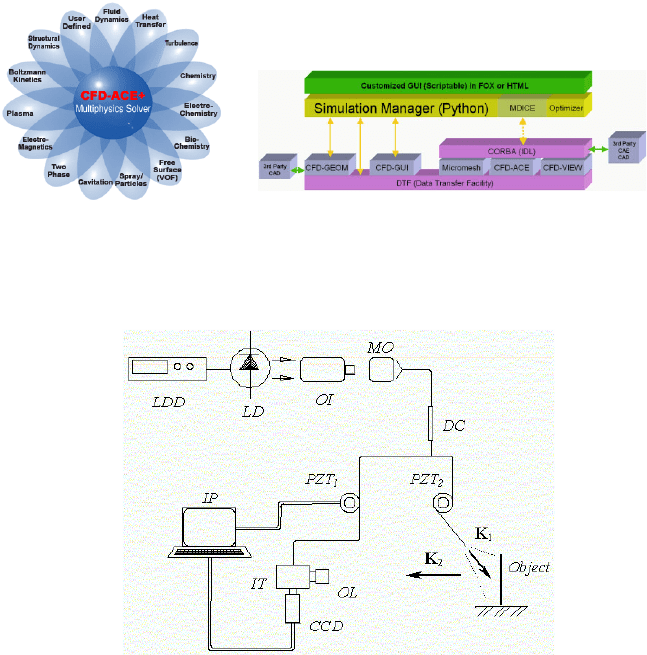
The coupled electrostatics-structures-flow simulations can also be performed
using CFD-ACE+ software because it has the necessary multiphysics capabilities
including flow, heat-transfer, mechanics, and electrostatics [27], as summarized in
Fig. 9. All CFD-ACE+ capabilities are fully coupled to facilitate fast solution and
determination of accurate results, Fig. 10.
3.3 Optoelectronic Methodology
The optoelectronic methodology, as presented in this paper, is based on the
principles of optoelectronic holography (OEH) [7,13,30]. Basic configuration of
the OEH system is shown in Fig. 11. In this configuration, laser light is launched
into a single mode optical fiber by means of a microscope objective (MO). Then,
the single mode fiber is coupled into two fibers by means of a fiber optic
directional coupler (DC). One of the optical fibers comprising the DC is used to
illuminate an object, while the output from the other fiber provides reference
against which the signals from the object are recorded. Both, the object and the
reference beams are combined by the interferometer (IT) and recorded by a system
camera (CCD).
Recent Advances in Microelectromechanical Systems and Their Applications 257
Fig. 9. Coupled multiphysics
structure of CFD-ACE+ software
for MEMS.
Fig. 10. CFD-ACE+ coupling capabilities.
Fig. 11. Single-illumination and single-observation geometry of a fiber-optic-based OEH
system: LDD is the laser diode driver, LD is the laser diode, OI is the optical isolator, MO is
the microscope objective, DC is the fiber optic directional coupler, PZT
1
and PZT
2
are the
piezoelectric fiber optic modulators, IP is the image-processing computer, IT is the
interferometer, OL is the objective lens, CCD is the camera, while K
1
and K
2
are the
directions of illumination and observation, respectively.
Images recorded using the CCD are processed by the system computer to
determine the fringe-locus function, Ω(x,y), constant values of which define fringe
loci on the surface of an object under investigation. The values of Ω relate to the
system geometry and the unknown vector L, defining displacements and
deformations, via the relationship [31]
() () ()
[]
()
,,,,
12
LKLKK •=•−=Ω yx,yxyxyx
(1)

258 R.J. Pryputniewicz
where K is the sensitivity vector defined in terms of vectors K
1
and K
2
identifying
directions of illumination and observation, respectively, (i.e., geometry) of the
OELIM system as illustrated in Fig. 11.
Quantitative determination of structural displacements/deformations due to the
applied loads can be obtained, by solving a system of equations similar to Eq. 1, to
yield [31]
[]
()
,
~~~
T
1
T
Ω=
−
KKKL (2)
where
T
~
K
represents a transpose of the matrix of the sensitivity vectors K.
Equation 2 indicates that displacements/deformations determined from
interferograms are functions of K and Ω, which have spatial, i.e., (x,y),
distributions over the field of interest on an object being investigated. Thus Eq. 2
can be represented by a phenomenological relation [11] as
()
,,Ω= KLL
(3)
based on which the RSS-type (i.e., the square Root of the Sum of the Squares)
uncertainty in L, i.e.,
L
δ
, can be determined to yield
,
2/1
22
⎥
⎥
⎦
⎤
⎢
⎢
⎣
⎡
⎟
⎠
⎞
⎜
⎝
⎛
Ω
Ω∂
∂
+
⎟
⎠
⎞
⎜
⎝
⎛
∂
∂
=
δδδ
L
K
K
L
L
(4)
where KL ∂∂ / and
Ω∂∂ /L
represent partial derivatives of L with respect to K
and Ω, respectively, while δK and δΩ represent the corresponding uncertainties in
K and Ω, respectively. It should be remembered that K, L, and Ω are all functions
of spatial coordinates (x,y,z), i.e., K = K(x,y,z), L = L(x,y,z), and Ω = Ω(x,y,z),
respectively, when performing partial differentiations required to solve Eq. 4.
After solution of Eq. 4, the result indicates that
L
δ
is proportional to a product of
the local value of L with the RSS value of the ratios of the uncertainties in K and
Ω to their corresponding local values, i.e.,
.
2/1
22
⎥
⎥
⎦
⎤
⎢
⎢
⎣
⎡
⎟
⎠
⎞
⎜
⎝
⎛
Ω
Ω
+
⎟
⎠
⎞
⎜
⎝
⎛
∝
δδ
δ
K
K
LL
(5)
For typical geometries of the OEH systems used in recording of interferograms,
the values of
KK /
δ
are less than 0.01. However, for small deformations, the
typical values of
ΩΩ/
δ
are (usually) more than one order of magnitude greater
than the values for
KK /
δ
. Therefore, the accuracy with which the fringe orders
(based on which Ω values are calculated [31]) are determined influences the
accuracy in the overall determination of displacements/deformations [32] and, as
