Koren B., Vuik K. (Editors) Advanced Computational Methods in Science and Engineering
Подождите немного. Документ загружается.

Simulation of Progressive Failure in Composite Laminates
1
2
3
4
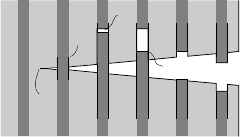
1 – Matrix cracking
2 – Fiber/matrix debonding
3 – Fiber failure
4 – Fiber pull-out
Fig. 3 Pull out process with different micromechanical failure mechanisms.
eventually predicted? If this can be done efficiently, the number of tests required to
assess the safety of a composite structure may be reduced drastically [10], while the
designer is given more freedom to exploit the structural capacity of the materials,
and the manufacturers are provided with tools to optimize their products.
Modeling of laminate failure is often endeavored on the mesolevel, where a lam-
inate is considered to be consisting of homogeneous plies, each with orthotropic
properties that depend on the fiber orientation. Although initiation and propaga-
tion of failure inside a ply are typically described on the microlevel, the mesolevel
approach is adopted because explicit modeling of the entire microstructure is com-
putationally unaffordable. As a consequence, assumptions must be made on how
to represent micromechanical failure in the homogenized model. Because the intact
ply is modeled as a continuum, a relatively straightforward way to represent fail-
ure is with a continuum failure model, i.e. by introducing softening behavior in the
homogenized constitutive law.
A popular continuum failure theory is the continuum damage model [25], in
which the stiffness of the material is reduced gradually after a certain failure cri-
terion has been violated. In the scope of orthotropic composite materials, several
continuum damage formulations have been proposed [7, 12, 21–24, 26–28, 36, 37],
with different degrees of complexity in failure criteria and degradation laws.
A well known problem with the application of continuum failure models is that a
mesh dependence is introduced, due to ill-posedness of the mathematical problem.
Localization of deformations will occur in one row of elements, which causes the
amount of dissipated energy to depend on the element size, approaching zero for
infinitesimally small elements. In several of the damage descriptions that have been
proposed for composites [22, 27, 37], this is mitigated with the crack band method,
in which the local stress strain behavior depends on the element size [2]. However,
this does not solve the mesh sensitivity problem completely; element shape and ori-
entation still influence the solution. Moreover, in the case of non-localized material
degradation, which may occur in laminates as distributed transverse matrix crack-
ing, this approach causes an opposite mesh dependency, i.e. a smaller element size
causes an increase in the amount of energy th at is dissipated.
For the development of reliable predictive tools, more advanced localization lim-
iters, which introduce an internal length scale in the model, are to be preferred, such
as non-local [3] and gradient models [5]. With these models, the localization zone
has a finite width, the mathematical problem is well-posed, and a truly mesh inde-
pendent solution exists, which will be obtained under the condition that the typical
345
F.P. van der Meer and L.J. Sluys
element size in the localization region is smaller than this width. Of these, the im-
plicit gradient model has been applied to anisotropic materials like composites by
Germain et al. [12]. Another possibility is to resolve mesh dependence with arti-
ficial viscosity [42, 49]. Artificial viscosity is an appealing option, because of its
easy implementation and limited extra computational costs, although it entails an
unphysical rate dependence and, consequently, difficulties in model calibration and
validation. Maim´ı et al. [27] and Lapczyk and Hurtado [22] already proposed to use
artificial viscosity, but only to improve stability of the simulation. In recent work,
we have presented a continuum damage model and a softening plasticity in both
of which artificial viscosity ensures mesh objectivity of the results [29]. Unfortu-
nately, the continuum models proved to be inadequate for the simulation of failure
mechanisms such as illustrated in Fig. 2.
Besides continuum failure theories, there are discontinuous failure models. With
these, failure is represented as a discontinuity in the displacement field instead of
as localized strain, and a cohesive zone may be modeled by defining tractions that
work on the crack surface as a function of the displacement jump. Examples of dis-
continuous failure methods are interface elements and the eXtended Finite Element
Method (XFEM). Interface elements are special elements that are placed between
regular continuum finite elements, and that allow the elements to separate after the
traction between the elements exceeds a certain threshold. In the context of compos-
ite materials, interface elements are regularly applied for the modeling of delamina-
tion [6,31,41, 45,53] and, more exceptionally, splitting [20,52,53] and fiber-matrix
debonding [8, 13]. With XFEM (or the partition of unity method) a discontinuity is
introduced inside the finite elements by adding degrees of freedom that are related
to discontinuous basis functions. This method has also been used for the simula-
tion of delamination [39, 50] and fiber-matrix debonding [38]. In comparison with
continuum models, discontinuous methods demand additional implementation ef-
fort, especially XFEM, but they allow for the use of larger elements to capture the
kinematics of the problem.
In this contribution, the performance of a continuum model for ply failure is
assessed along with that of a discontinuous method for splitting. A limitation of
continuum models for the modeling of matrix failure is illustrated, and the discon-
tinuous method is presented as an alternative. Section 2 deals with the continuum
damage model and Section 3 with the phantom node method, which is equivalent to
the above mentioned XFEM, but differs in implementation.
2 Continuum damage
In this section, a continuum damage model for a homogenized unidirectional ply
is presented. In recent years, several comparable models have been introduced (see
e.g. [22,23,26–28,37]). Attention is given to three essential ingredients in three sub-
sections. Firstly, the material degradation laws, which form the core of the constitu-
tive model, viz. the procedure with which stress is computed from strain. Secondly,
346
Simulation of Progressive Failure in Composite Laminates
the consistent tangent formulation, which is necessary for robustness of the Newton-
Raphson procedure in implicit nonlinear finite element analysis. And thirdly, the
regularization method, which is necessary to obtain mesh independent results. In
subsections 2.4 and 2.5 the performance of the continuum damage model is as-
sessed, with emphasis on its insufficiency for capturing matrix failure patterns.
2.1 Material degradation
In the continuum damage theory, material degradation is understood as the devel-
opment of voids, defects or microcracks, which reduce the effective volume of the
material. The effective stress
ˆ
σ
is the stress acting on the intact material, computed
with linear elasticity
ˆ
σ
= D
e
ε
, (1)
in which D
e
is the elastic stiffness matrix and
ε
is the strain in the bulk material.
1
2
3
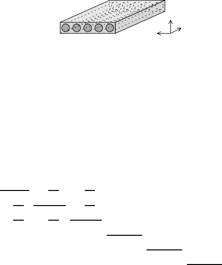
Fig. 4 Local coordinate system for unidirectional ply aligned with fiber direction.
The constitutive law which relates nominal stress
σ
to strain, using small strain
theory, is written in the form
ε
= C
σ
, (2)
where C is the secant compliance matrix, and
ε
and
σ
contain strain and stress values
in the local coordinate frame of the ply (see Fig. 4). Following Matzenmiller et
al. [28], damage is taken into account via modification of the values on the diagonal
of the compliance matrix (in Voigt notation) as:
C =
1
(1−
˜
d
f
)E
1
−
ν
21
E
2
−
ν
21
E
2
0 0 0
−
ν
21
E
2
1
(1−
˜
d
m
)E
2
−
ν
23
E
2
0 0 0
−
ν
21
E
2
−
ν
23
E
2
1
(1−
˜
d
m
)E
2
0 0 0
0 0 0
1
(1−
˜
d
m
)G
23
0 0
0 0 0 0
1
(1−
˜
d
m
)G
12
0
0 0 0 0 0
1
(1−
˜
d
m
)G
12
, (3)
where
˜
d
f
and
˜
d
m
are the damage variables related to fiber failure and matrix fail-
ure, respectively, E
1
and E
2
are the longitudinal and transverse Young’s moduli,
ν
21
347

F.P. van der Meer and L.J. Sluys
and
ν
23
are the longitudinal and transverse Poisson ratios, and G
12
and G
23
are the
longitudinal and transverse shear moduli, with G
23
= E
2
/(2 + 2
ν
23
). The assump-
tion that the components C
22
–C
66
evolve synchronously is debatable, but considered
acceptable for the in-plane load cases presented in this paper.
Hashin’s failure criteria [18, 19] are applied to evaluate the effective stress state.
The criteria for different failure modes are the following:
• Tensile fiber mode:
f
ft
=
ˆ
σ
1
F
1t
, (4)
• Compressive fiber mode:
f
fc
= −
ˆ
σ
1
F
1c
, (5)
• Tensile matrix mode:
f
mt
=
r
(
ˆ
σ
2
+
ˆ
σ
3
)
2
F
2
2t
+
ˆ
τ
2
23
−
ˆ
σ
2
ˆ
σ
3
F
2
23
+
ˆ
τ
2
31
+
ˆ
τ
2
12
F
2
12
, (6)
• Compressive matrix mode:
f
mc
=
s
F
2c
2F
23
2
−1
ˆ
σ
2
+
ˆ
σ
3
F
2c
+
(
ˆ
σ
2
+
ˆ
σ
3
)
2
4F
2
23
+
ˆ
τ
2
23
−
ˆ
σ
2
ˆ
σ
3
F
2
23
+
ˆ
τ
2
31
+
ˆ
τ
2
12
F
2
12
, (7)
where F
1t
and F
1c
are the tensile and compressive strength in fiber direction, F
2t
and F
2c
are the tensile and compressive transverse strength, and F
23
and F
12
are
the transverse and longitudinal shear strength. The numeric subscripts in the stress
components
σ
1
. . .
τ
12
refer to the local coordinate system in the ply (see Figure 4).
With the failure criteria, the two loading functions
φ
i
, one corresponding to fiber
failure and the other to matrix failure, are evaluated:
φ
f
=
f
ft
,
ˆ
σ
1
≥ 0,
f
fc
,
ˆ
σ
1
< 0,
(8)
φ
m
=
f
mt
,
ˆ
σ
2
+
ˆ
σ
3
≥ 0,
f
mc
,
ˆ
σ
2
+
ˆ
σ
3
< 0.
(9)
For both fiber and matrix failure, there is a single state variable r
i
. For simplicity,
there is no distinction between compressive and tensile failure regarding the influ-
ence on the state of the material. An artificial viscosity, limiting the rate of state
variable r
i
, is introduced for regularization, such that the evolution of r
i
is defined
as (cf. [1, 21, 54])
˙r
i
= B
i
1 −
1
φ
i
−r
i
, i = f,m, (10)
348
Simulation of Progressive Failure in Composite Laminates
where B
i
is the maximum rate with which r
i
is allowed to increase and the operator
h·i = max{·,0} is used to ensure irreversibility of the damage process. In the rate
independent limit B
i
→ ∞, Eq. (10) reduces to r
i
= sup(
φ
i
−1).
Damage variables
˜
d
i
are computed from r
i
according to
˜
d
i
= min
1,
A
i
r
i
(r
i
+ 1)(A
i
−1)
, i = f,m, (11)
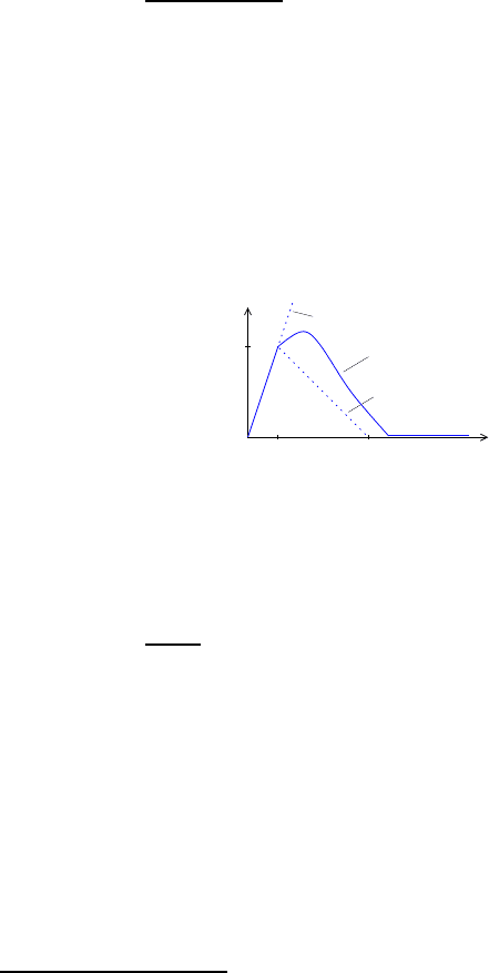
which corresponds to a bilinear stress-strain relation for uni-axial tests without vis-
cosity. Initially
˜
d
i
= r
i
= 0 and when
˜
d
i
= 1 the material has failed in either fiber
of matrix mode
1
. The softening parameter A
i
is related to the strain level at which
complete failure occurs in this bilinear relation (see Fig. 5), and hence to the fracture
energy dissipated in a uni-axial test, which is generally considered a material con-
stant. With these, the secant compliance matrix is computed (Eq. (3)), and inverted
to obtain the secant stiffness matrix, which is in turn used to compute the nominal
stress.
B
f
→ ∞
B
f
= 0
0 < B
f
< ∞
F
1t
σ
1
A
f
ε
0
ε
0
ε
1
Fig. 5 Schematic representation of uni-axial stress-strain relation for continuum damage with ar-
tificial viscosity.
For postprocessing, a variable d
i
is introduced, which is defined as
d
i
= min
1,
r
i
A
i
−1
, i = f,m. (12)
Note that
˜
d
i
= 0 ⇔d
i
= 0 and
˜
d
i
= 1 ⇔d
i
= 1. For minor damage, d
i
increases less
rapidly than
˜
d
i
.
2.2 Consistent tangent
For robustness of the incremental iterative finite element analysis, it is necessary
to employ the consistent tangent stiffness matrix, the derivation of which is given
below for the presented continuum damage model.
1
To avoid singularity in the stiffness matrix, the maximum value of
˜
d
i
is set to 1 −10
−5
instead of
1.
349

F.P. van der Meer and L.J. Sluys
Expanding the constitutive law, Eq. (2), around a small variation in stress and
strain gives
δε
=
δ
C
σ
+ C
δσ
. (13)
The secant compliance C depends on strain via the damage law, therefore the varia-
tion in the compliance may be written as
δ
C =
∂
C
∂ε
δε
. (14)
Because only the values on the diagonal of C depend on the strain, the first term of
the right-hand side of (13) may be rewritten (in index notation) as
δ
C
i j
σ
j
=
δ
i j
∂
C
i j
∂ε
k
δε
k
σ
j
=
σ
i
∂
C
ii
∂ε
k
δε
k
= M
ik
δε
k
,
(15)
where
δ
i j
is the Kronecker delta and
M
ik
=
σ
i
∂
C
ii
∂
˜
d
p
∂
˜
d
p
∂
r
p
∂
r
p
∂φ
p
∂φ
p
∂
ˆ
σ
q
∂
ˆ
σ
q
∂ε
k
, p = f,m. (16)
The artificial viscosity is accounted for in the evaluation of
∂
r
p
/
∂φ
p
.
Substitution of (15) into (13) and reordering gives
[I −M]
δε
= C
δσ
. (17)
Hence, the consistent tangent for the continuum damage model is defined as
D
con
=
∂σ
∂ε
= C
−1
[I −M]. (18)
2.3 Regularization
The model described above contains a viscous term. In this section, it is shown that
introduction of this term gives rise to mesh independent results. For this purpose,
we consider a bone shaped specimen loaded in tension (see Fig. 6); the geometry
is such that localization is forced to take place at the middle of the specimen. The
material properties are as summarized in Table 1, with the strong direction aligned
with the load. 8-Node brick elements are used with only one element in width and
thickness direction. The elements are equidistributed in size along the length of the
350
Simulation of Progressive Failure in Composite Laminates
specimen. For all analyses presented with the continuum damage model, the loading
rate is
˙
ε
= 1% s
−1
, where
ε
is the averaged strain in load direction.
Table 1 Material parameters for mesh refinement study and notched plate analysis.
Elasticity [53] Ply strength [11] Damage
E
1
140 GPa F
1t
2280 MPa A
f
15
E
2
10 GPa F
1c
1725 MPa A
m
2
ν
12
0.21
F
2t
76 MPa B
f
40 s
−1
ν
23
0.21
F
2c
228 MPa B
m
10 s
−1
G
12
5 GPa F
12
76 MPa
F
23
76 MPa
l = 20
w = 1.6 −0.6sin(
π
x/l)
t = 0.4
Fig. 6 Geometry of bone shaped specimen, dimensions in mm.
0 0.2 0.4 0.6
0
0.2
0.4
0.6
0.8
1
5
9
19
49
99
u (mm)
F (kN)
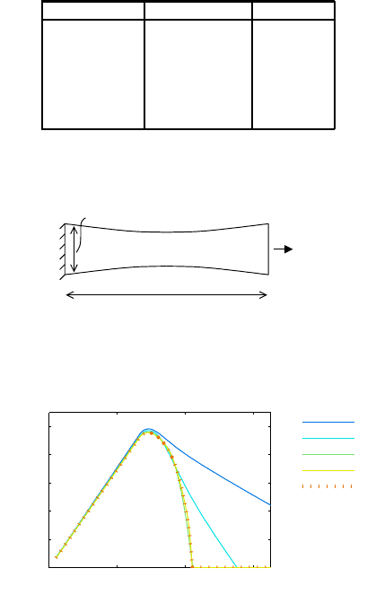
Fig. 7 Response of bone shaped specimen converges to a unique solution upon mesh refinement.
The load displacement diagrams obtained in a mesh refinement study are shown
in Fig. 7. It can be observed that the results converge to a unique solution with
a finite amount of dissipated energy. The meshes with 5 and 9 elements are too
coarse, which can be explained as that, with these meshes, the width of the localized
zone is smaller than one finite element. The strain evolution for the solution with 99
elements is shown in Fig. 8, in which the profile of axial strain over the specimen
length is depicted for a number of time levels. In both cases, the localization zone is
wider than one element, witness the smoothness of the curves, which were obtained
by connecting the mid-element strain values.
351

F.P. van der Meer and L.J. Sluys
0 0.2 0.4 0.6 0.8 1
0
0.2
0.4
0.6
0.8
x/L
ε
x
Fig. 8 Localization of strain in analysis with 99 elements.
2.4 Notched plate
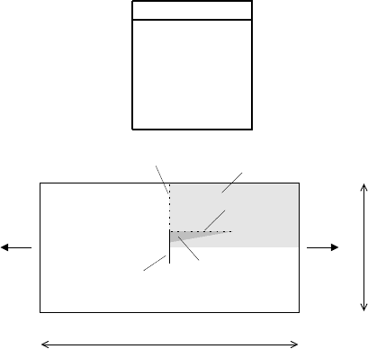
An analysis which has many of the components of the typical complex laminate fail-
ure, as illustrated in Fig. 2, is the case of a rectangular [0/90]
s
laminated plate
2
with
an interior notch (see Fig. 9). In experiments it has been observed that well before
failure a splitting crack grows from the notch tip in the 0
◦
-ply, which is accom-
modated by delamination [44]. After that, ultimate failure occurs in both plies in
the plane of the notch. This case has been analyzed computationally by Wisnom
and Chang [52] and by Yang and Cox [53], who modeled the split with spring or
interface elements. Here we examine whether it is also possible to use continuum
models. This is motivated by the higher predictive potential of continuum models,
since it is not necessary to specify the location of the crack in advance. Moreover,
extension of the simulation to ultimate failure of the laminate is possible.
In the numerical model only the upper two plies are taken into account, due to
symmetry. Both in-plane axes of symmetry are also used to reduce the size of the
model. Each ply is modeled with a single layer of 8-node brick elements. To allow
for delamination, the plies are connected with interface elements. These are inte-
grated with a Newton-Cotes scheme to avoid spurious oscillations [40]. Failure in
the interface elements, which have an initial elastic dummy stiffness K, is modeled
with the damage law developed by Turon et al. [45], containing five material pa-
rameters: normal strength t
n
, shear strength t
s
, mode I fracture energy G
I
, mode II
fracture energy G
II
and mode interaction parameter
η
. Values provided by Daniel
and Ishai [11] and Yang and Cox [53] for carbon epoxy laminates are used as lam-
ina and interface properties (see Tables 1 and 2). Interfacial strength parameters are
reduced as proposed by Turon et al. [46] in order to allow for a relatively coarse
mesh.
Results from two subsequent analyses are presented.
2
That is, the fibers in top and bottom ply are parallel to the x-axis, and those in the two middle
plies are perpendicular to the x-axis
352
Simulation of Progressive Failure in Composite Laminates
Table 2 Material parameters for interface in notched plate analysis [53].
Interface
K 5×10
5
N/mm
t
n
25 MPa
t
s
15 MPa
G
I
0.35 N/mm
G
II
0.7 N/mm
η
1
100 mm
49.2 mm
[0/90]
s
t = 0.8 mm
ultimate failure
split
delamination
quarter plate modeled
8 mm notch
Fig. 9 Geometry and expected failure for notched plate analysis.
1. The 0
◦
ply is analyzed with the damage model, and the 90
◦
ply is kept elastic
(just as it is in [53]). The parameters are calibrated to realize approximately the
same amount of delamination due to splitting as presented by Yang and Cox [53].
2. Both plies are analyzed with the damage model, with the same data as for the
0
◦
ply in the previous analysis. This is supposed to be the most realistic input,
because the plies are made of the same material and differ only in orientation.
Firstly, results are presented from the analysis with the continuum damage model
assigned to the 0
◦
-ply and elastic properties assigned to the 90
◦
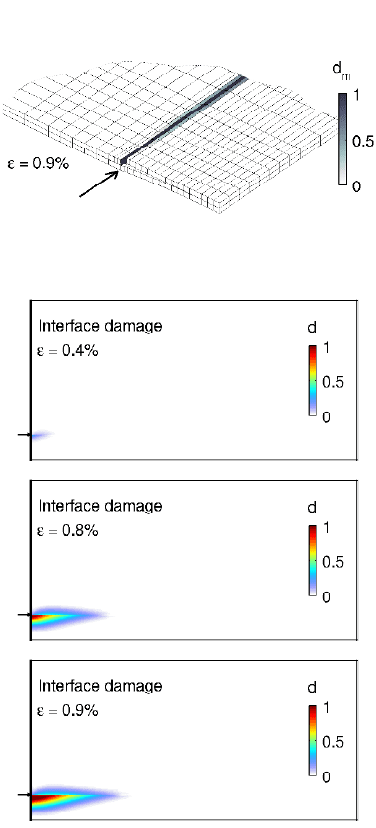
-ply. In Fig. 10, the
deformed mesh is shown for both material models. Note that the strain level is such
that tensile failure in the plane of the notch has not yet initiated. The localization
zone related to the split is wider than the typical element size, which means that the
viscous regularization effectively preserves the mesh objectivity of the results.
Figure 11 shows the damage in the interface for different strain levels. The strain
levels for which results are plotted are the same as in [53], and the agreement is
satisfactory: there is strong resemblance in shape of the delaminated area, delami-
nation has initiated before
ε
= 0.4%, a traction free zone appears between
ε
= 0.4%
and
ε
= 0.8% and this zone grows rapidly before
ε
= 0.9%. The cohesive zone in
the interface, i.e. the zone where 0 < d < 1, is wider than in the results presented by
Yang and Cox. This is the intended effect of the reduction of the interface strength
as proposed by Turon et al. [46] in order to allow for the use of relatively coarse
meshes.
Secondly, the damage model is assigned to the 90
◦
-ply as well. This is supposed
to be the most realistic representation, since both plies are of the same material. In
Fig. 12, deformed meshes from both analyses are shown from two different perspec-
353
F.P. van der Meer and L.J. Sluys
Fig. 10 Deformed mesh from analysis with elastic 90
◦
-ply and continuum damage in the 0
◦
-ply.
Fig. 11 Evolution of delamination damage with continuum damage in 0
◦
-ply and elastic 90
◦
-ply
tives. Unrealistic failure behavior is obtained. For both material models, localized
strains appear in the 90
◦
-ply following the split in the 0
◦
-ply. As a consequence,
there is no delamination. Apparently, the damage related to this localized strain in
the 90
◦
-ply consumes less energy than what would be needed to cause the expected
delamination.
Apparently, something is wrong with the continuum damage model, such that
a band with matrix failure that is not aligned with the fibers can be formed more
354
