Kamal A.A. 1000 Solved Problems in Classical Physics: An Exercise Book
Подождите немного. Документ загружается.

740 15 Optics
15.19 For a thin lens d = 0. The t ransformation matrix then becomes
(see prob. 15.18)
10
P
23
+ nP
12
1
or
⎛
⎝
10
−(n − 1)
1
r
1
−
1
r
2
1
⎞
⎠
or
⎛
⎝
10
−
1
f
0
⎞
⎠
Thus −
1
f
1
−
1
f
2
=−
1
f
or
1
f
1
+
1
f
2
=
1
f
15.3.4 Interference
15.20 A constant phase difference implies a constant difference in length between
r
1
and r
2
,Fig.15.28:
r
1
−r
2
= 2a (1)
(x + d)
2
+ y
2
−
(d − x)
2
+ y
2
= 2a (2)
Transposing the second radical
(x + d)
2
+ y
2
= 2a +
(d − x)
2
+ y
2
(3)
Fig. 15.28 Locus of a point
with constant phase
difference from two coherent
point sources s
1
and s
2
Squaring and simplifying
x
2
(d
2
− a
2
) − y
2
a
2
= a
2
(d
2
− a
2
) (4)
Dividing by a
2
(d
2
− a
2
)
x
2
a
2
−
y
2
d
2
− a
2
= 1(5)
Since 2d > 2a or d > a, d
2
−a
2
will be positive. Writing d
2
−a
2
= b
2
,(5)
becomes
15.3 Solutions 741
x
2
a
2
−
y
2
b
2
= 1(6)
This is the equation of a hyperbola with the centre at the origin and the foci
on the x-axis. In three dimensions, the locus of P would be a hyperboloid,
the figure of revolution of the hyperbola.
In an actual Young’s experiment on the observation of interference fringes
one looks at a limited field of view and consequently the central portions of
hyperbolas appear as straight lines as in Fig. 15.29 (within the dotted lines).
Fig. 15.29 Interference
fringes in Young’s
experiment
15.21 At any point P on the screen at a distance y from the axis, the phase difference
due to the waves coming from S
1
and S
2
will be due to the optical path
difference (S
2
P − S
1
P), Fig. 15.11:
δ =
2π
λ
(S
2
P − S
1
P) (1)
If (S
2
P − S
1
P) = nλ(n = 0, 1, 2,...), the phase difference δ = 2nπ , and
the intensity is maximum at P:
If (S
2
P − S
1
P) =
m +
1
2
λ, where m = 0, 1, 2,..., the phase differ-
ence, δ = (2m + 1)π and the intensity will be zero at P. With reference to
Fig. 15.11,
(S
2
P)
2
= L
2
+ (x + d/2)
2
(S
1
P)
2
= L
2
+ (x − d/2)
2
∴ (S
2
P)
2
− (S
1
P)
2
= (S
2
P + S
1
P)(S
2
P − S
1
P) = 2xd
In practice d is quite small, typically 0.5 mm, compared to L, typically 1.0 m,
and P is close to the axis, y << L, so that S
1
PaswellasS
2
P are only
slightly greater than L. We can then set S
2
P + S
1
P = 2L. Therefore
S
2
P − S
1
P =
2xd
2L
=
xd
L
(2)

742 15 Optics
Therefore, the condition for maximum intensity at P is
xd
L
= mλ (bright fringes) (3)
and the condition for zero intensity at P is
xd
L
=
m +
1
2
λ (dark fringes) (4)
m is called the order of fringe system. On the axis, at y = 0, m = 0 and
we have the intensity maximum. The central bright band on the screen is
flanked on either side by a series of b bright and dark bands corresponding to
m = 1, 2, 3,...,themth bright fringe being at a distance y
m
from the axis:
y
m
=
mλL
d
(5)
and the (m + 1)th bright fringe being at a distance
y
(m+1)
=
(m + 1)λL
d
(6)
The separation of the fringes β called the bandwidth is given by
y = y
(m+1)
− y
m
= β =
λL
d
(7)
β =
λL
d
=
612 × 10
−9
× 4
2 × 10
−3
= 1.124 ×10
−3
m = 1.124 mm
15.22 Let a transparent plate of thickness t and refractive index μ be introduced
in the path of one of the two interfering beams of monochromatic light,
Fig. 15.30. A ray travelling from S
1
to O covers a distance t in the plate
while the rest of the distance (S
1
O−t) is covered in air. The effective optical
path length would be
μt + (S
1
O − t) or S
1
O + (μ − 1)t
The optical path length for the ray emanating from S
2
would be S
2
O. Clearly
S
1
O + (μ − 1)t > S
2
O
Consequently, the central fringe corresponding to zero path difference is not
formed at O, the normal position of the central fringe in the absence of the
plate. The new position of the central fringe would be at O
such that
S
1
O
+ (μ − 1)t = S
2
O
15.3 Solutions 743
Fig. 15.30 Shift of fringes
when a transparent plate is
introduced in the path of one
of the rays in Young’s
double-slit experiment
But S
2
O
− S
1
O
=
d
L
· OO
Calling OO
= , the distance through which the central fringe shifts,
=
L
d
(μ − 1) t
Furthermore, (μ − 1)t = nλ.
This shift is towards the side on which the plate is placed.
Note that the bandwidth of the fringe system is unaffected and the entire
fringe system undergoes a lateral shift.
With the use of monochromatic light it is not possible to detect shift of
fringes. However, if white light is used then the central fringe being white
is easily distinguished from the coloured fringes and its shift can be easily
measured. Thus, by the use of the above procedure the thickness of the plate
can be accurately measured.
15.23
(a) Let two light waves of the same wavelength λ and amplitude A pass
through a given point and be represented by
y
1
= A sin ωt (1)
y
2
= A sin(ωt − δ) (2)
where ω = 2πν and δ = constant phase difference between the two
waves. The resulting displacement is then given by
y = y
1
+ y
2
= A sin ωt + A sin(ωt − δ)
= 2A cos
δ
2
sin
ωt −
δ
2
(3)
744 15 Optics
where we have used the identity
sin B + sin C = 2sin
B +C
2
cos
B −C
2
(4)
Equation (3) represents simple harmonic vibration of frequency ω/2π
and amplitude A
= 2A cos(δ/2). The amplitude of the resulting wave
varies from 2A through 0 to −2A according to the value of δ. The result-
ing intensity I at the given point is proportional to the square of the
amplitude or A
2
:
I ∝ 4A
2
cos
2
δ
2
(5)
If δ = (2n + 1)π(n = 0, 1, 2,...) then A
= 0, i.e. the crests of one
wave coincide with the troughs of the other, the two waves interfere
destructively to give zero intensity, i.e. darkness.
If δ = 2nπ, then A
= 2A, i.e. the two waves interfere constructively
to produce maximum intensity of 4A
2
. Here the crests of one wave are
an integral number of wavelengths ahead of crest of the other so that the
waves are reinforced:
By eqn (1), prob. (15.21),δ=
2π
λ
(S
2
P − S
1
P) =
2π
λ
dx
L
∴ I = 4A
2
cos
2
πd x
λL
(6)
Figure 15.31 shows the intensity distribution of Young’s fringes. Here x
is measured on the screen. The bright central fringe occurs at x = 0,
in the centre of the fringe system. The other bright fringes are sep-
arated by distance, x = λ L/d,2λ L/d,3λ L/d ...on either side.
Halfway between two neighbouring bright fringes, the centres of dark
fringes occur. The light intensity does not drop off suddenly but varies
as cos
2
(δ/2). At maxima the intensity reaches a value of 4A
2
, and at
minima, it is equal to zero. At other points it is given by (6). Thus the
intensity in the interference pattern varies between 4A
2
and zero. In the
absence of interference each beam would contribute A
2
so that from two
incoherent sources, there would be a uniform intensity of 2A
2
, which is
indicated by the horizontal dotted line.
Fig. 15.31 Intensity
distribution of fringes in
young’s double-slit
experiment

15.3 Solutions 745
(b) Now the average intensity of the interference pattern is obtained by aver-
aging over the cos
2
function in (6)
< I >=
λL/d
0
Idx
λL/d
0
dx
=
4A
2
λL/d
0
cos
2
(πd x/λL)dx
λL/d
= 2A
2
(7)
The average intensity is equal to 2A
2
as expected. Although at maximum
the intensity is double t he average value, at minima, it becomes zero and
on the whole it averages out to 2A
2
. Hence there is no violation of energy
conservation.
15.24 u + v = D = 100 cm → v = 100 −u = 100 − 30 = 70 cm
I
O
=
0.7
O
=
v
u
=
70
30
∴ 2d = O = 0.30 cm (distance between two coherent sources)
β =
.λD
2d
(bandwidth)
∴ λ =
2dβ
D
=
(0.3)(0.0195)
100
= 5.85 ×10
−5
cm = 5850 Å
15.25
D = y
1
+ y
2
= 10 +100 = 110 cm
2d = 2(μ − 1)y
1
α = 2 × (1.5 − 1) ×
2
57.3
× 10
= 0.349 cm
λ =
(2d)β
D
=
0.349 × 0.018
110
= 5.711 ×10
−5
cm
= 5711 Å.
15.26
θ = 20 s =
20
3600
×
1
57.3
rad
= 9.695 ×10
−5
rad
β =
λ
2μθ
=
5.82 × 10
−5
cm
2 × 1.5 × 9.695 × 10
−5
= 0.2cm
Number of fringes per centimetre=
1
β
=
1
0.2
= 5.
15.27
θ =
λ
2μβ
=
6 × 10
−5
cm
2 × 1.4 × (0.2cm)
= 1.07 ×10
−4
rad
= 1.07 ×10
−4
× 57.3
◦
= 22
of arc.
746 15 Optics
15.28 The radius of the nth dark ring is given by
r
n
=
√
nλR (1)
The radius of the (n +m)th dark ring is given by
r
n+m
=
(n + m)λR (2)
Squaring (1) and (2), subtracting and solving for R, the radius of curvature
of lower lens
R =
r
2
n+m
−r
2
n
mλ
=
r
2
n+20
−r
2
n
20λ
=
(0.368)
2
− (0.162)
2
20 × 5.46 × 10
−5
= 100 cm
15.29
r
n
=
√
nλR (darkringinair)
r
n
=
nλR/μ (dark ring in liquid)
∴ μ =
r
2
n
r
2
n
=
60
2
50
2
= 1.44
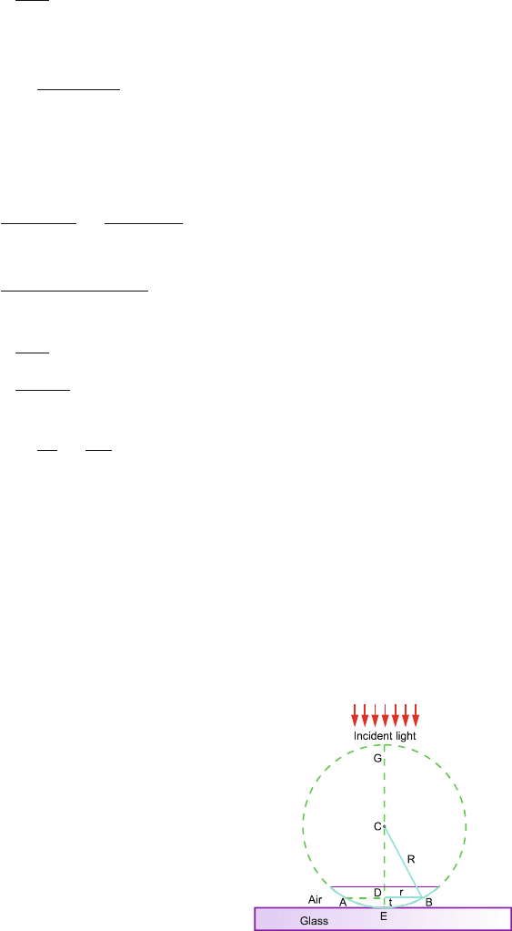
15.30 First, we calculate the air thickness t of the air gap between the horizontal
surface and the lower surface of the lens where Newton’s ring is formed as
in Fig. 15.32.
DE = t is the thickness of air gap; CB = R, the radius of curvature of
the lens; and DA = DB = r is the radius of the ring. From a theorem in
geometry on intersecting chords
DE × DG = DA × DB
Fig. 15.32 Newton’s rings
with convex lens on a flat
surface
15.3 Solutions 747
or t × (2R − t) = r
2
∴ t =
r
2
2R
(∵ t << 2R) (1)
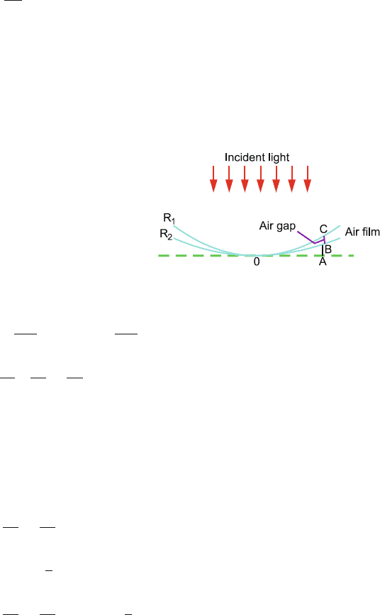
(a) Centres of curvature on the same side.
An air film BC is formed sandwiched between two curved surfaces of
radii R
1
and R
2
in contact at O. The centres of curvature of lenses are
on the same side, Fig. 15.33a. The thickness of air film
t = BC = AC −AB
Fig. 15.33 a Newton’s rings
formed by two curved
surfaces with the centres of
curvature on the same side
Using (1)
AC =
r
2
m
2R
1
; AB =
r
2
m
2R
2
t =
r
2
m
2
1
R
1
−
1
R
2
(2)
where r
m
is the radius of the mth ring:
2t = mλ(dark rings) (3)
Eliminating t between (2) and (3)
r
2
m
1
R
1
−
1
R
2
= mλ(m = 0, 1, 2,... dark rings) (4)
2t =
m +
1
2
λ (bright rings) (5)
r
2
m
1
R
1
−
1
R
2
=
m +
1
2
λ(m = 0, 1, 2,... bright rings)
(6)
(b) Centres of curvature on the opposite side
The surfaces in contact at O are as in Fig. 15.33b; the thickness of air
film t is
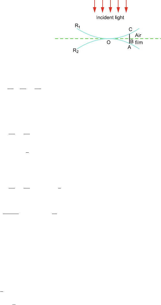
748 15 Optics
Fig. 15.33 b Newton’s rings
formed by two curved
surfaces with centres of
curvature on the opposite side
AC = BC + AB
t =
r
2
m
2
1
R
1
+
1
R
2
(7)
2t = mλ (dark fringes) (8)
Eliminating t between (7) and (8)
r
2
m
1
R
1
+
1
R
2
= mλ(m = 0, 1, 2 ..., dark fringes) (9)
2t =
m +
1
2
λ (bright fringes) (10)
Eliminating t between (7) and (10)
r
2
m
1
R
1
+
1
R
2
=
m +
1
2
λ(m = 0, 1, 2 ..., bright fringes)
(11)
15.31
x
m
=
m λ
1
D
d
= (m + 1)λ
2
D
d
m × 780 = (m + 1) ×520
∴ m = 2
15.32 Let the amplitude of the incident beam be a and intensity I :
I = a
2
The intensity of the reflected beam from the first face, Fig. 15.13
I
1
=
1
4
I (by problem)
∴ a
1
=
a
2
15.3 Solutions 749
The intensity of the transmitted beam at the first face will be
I
1
=
3
4
I
The corresponding amplitude will be
a
1
=
√
3
2
a
The reflected beam at the second face will have amplitude
a
1
=
1
2
×
√
3
2
a =
√
3
4
a
The emerging beam from the first face will have amplitude
a
2
=
√
3
2
a
1
=
√
3
2
√
3
4
a =
3
8
a
The two beams reflected from the first face will interfere:
I
min
I
max
=
(a
1
− a
2
)
2
(a
1
+ a
2
)
2
=
a
2
−
3
8
a
2
a
2
+
3
8
a
2
=
1
49
15.33 For constructive interference
2 μt =
m +
1
2
λ
∴ λ =
2μt
m +
1
2
=
2 × 1.5 × 4 × 10
−5
m +
1
2
=
12 × 10
−5
m +
1
2
cm
Only for m = 2, we get λ = 4.8×10
−5
cm or 4800 Å, corresponding to blue
colour in the visible region.
15.34 2μt cos r = mλ (minima)
For smallest thickness, m = 1
t =
mλ
2μ cos r
=
1 × 5890
2 × 1.5 × cos 60
◦
= 3927 Å