Jones D.S.J., Pujado P.R. Handbook of Petroleum Processing
Подождите немного. Документ загружается.

886 CHAPTER 18
The tray dimensions and configuration for design purposes are subject to a much more
rigorous examination. This is normally undertaken by the tray manufacturer from data
supplied by the purchaser’s process engineer. However this process engineer needs to
be able to check the manufacturer’s offer before committing to purchase. The following
calculation procedure offers a rigorous method for this purpose which establishes tray
size and geometry. This calculation is based on a method developed by Glitsch Inc.,
a major manufacturer of valve and other types of trays and packing.
The rigorous method
A rigorous method used in the design of valve trays is described by the following
calculation steps:
Step 1. Establish the liquid and vapor flows as described earlier for the “quickie”
method.
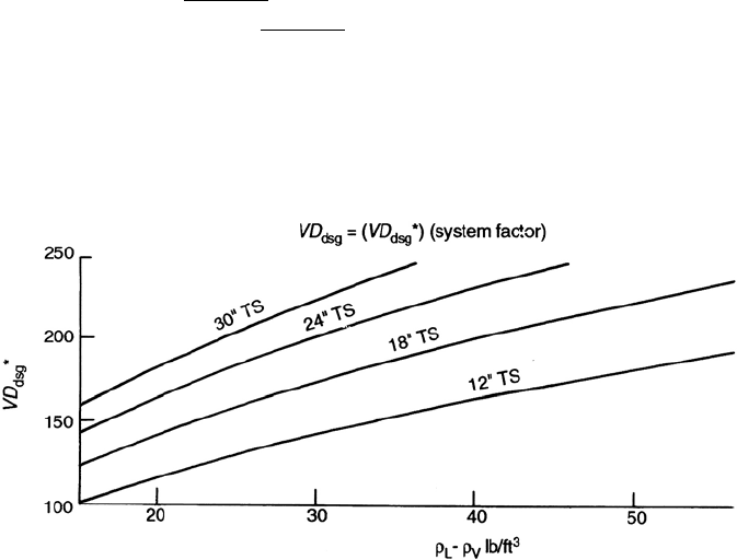
Step 2. Calculate the down comer Design Velocity V
dc
using the following equations
(or by Figure 18.5).
(a) V
dc
= 250 × system factor
(b) V
dc
= 41 ×
(ρ
L
− ρ
v
) × system factor.
(c) V
dc
= 7.5 ×
√
TS ×
(ρ
L
− ρ
v
) × system factor
where TS = Tray spacing, in inches
Use the lowest value for the design velocity in gpm/sqft.
Down comer System Factors are given in Table 18.1.
Figure 18.5. Down-comer design velocity.

PROCESS EQUIPMENT IN PETROLEUM REFINING 887
Table 18.1. Down comer system factors
Service System factor
Non foaming, regular system 1.0
Fluorine systems 0.9
Moderate foaming (amine units) 0.85
Heavy foaming (glycol, Amine) 0.73
Severe foaming (MEK units) 0.6
Foam stable systems (caustic regen) 0.3
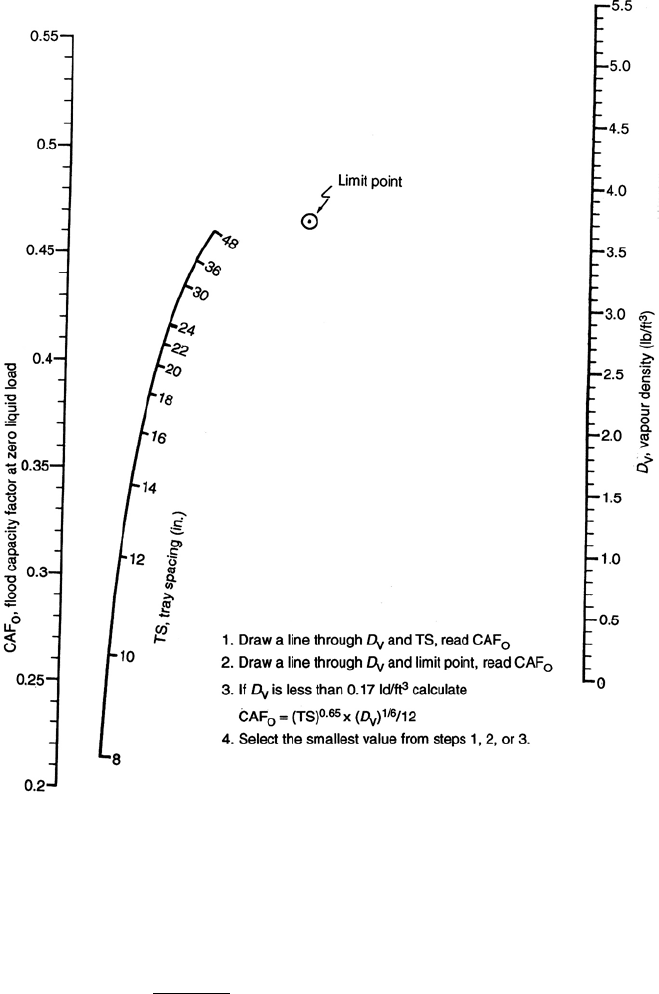
Step 3. Calculate the Vapor Capacity Factor CAF using Figure 18.6.
CAF = CAFo ×system factor.
System factors used for this equation are given in Table 18.2.
Step 4. Calculate the vapor load using the equation:
V
l
= CFS
ρ
v
/(ρ
L
− ρ
v
)
where CFS = actual vapor flow in cuft/sec.
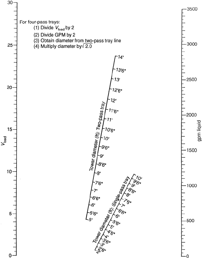
Step 5. Establish tower diameter using Figure 18.7. Tray spacing is usually 18
,24
,
or 30
for normal towers operating at above atmospheric pressures. Large vacuum
towers may have tray spacing 30 to 36
. Note this diameter may be increased if
other criteria of tray design are not met.
Step 6. Calculate the approximate Flow Path Length (FPL) based on tower diameter
from Step 5 using the equation:
FPL = 9 × DT/NP
where
FPL = Flow Path Length in ins.
DT = Tower Diameter from step 5 in ft
NP = Number of passes. For small towers with moderate liquid flows this will
be 1. For larger towers this will depend on liquid velocities in the down comer. The
highest number of passes is usually 4.
Step 7. Calculate the minimum active area (AA
m
) using the expression:
AA
m
=
V
l
+ (L × FPL/13,000)
CAF × FF
where
AA
m
= Minimum active area in sqft.
V
1
= Vapor load in CFS.
L = Liquid flow in actual gpm.
888 CHAPTER 18
Figure 18.6. Flood capacities of valve trays.
FPL = Flow path length in ins.
CAF = Capacity Factor from Step 3.
FF = Flood Factor usually 80–82%.
Step 8. Calculate minimum down comer area (AD
m
) using the equation
AD
m
=
L
V
dc
× 0.8

PROCESS EQUIPMENT IN PETROLEUM REFINING 889
Table 18.2. Vapor system factors
Service System factor
Non-foaming, regular 1.0
Fluorine systems 0.9
Moderate foaming 0.85
Heavy foaming 0.73
Severe foaming 0.6
Foam stable system 0.3–0.6
where
AD
m
= minimum down comer area in sqft
L = Actual liquid flow in gpm
V
dc
= Design down comer velocity from step 2.
Note: The down comer liquid velocity using the calculated minimum down comer
area should be around 0.3 to 0.4 ft/sec.
Step 9. Calculate the minimum tower cross-sectional area using the following equa-
tions:
AT
m
= AA
m
+ 2AD
m
or
AT
m
=
V
l
0.78 × CAF × 0.8
where
AT
m
= minimum tower cross-sectional area in sqft.
Step 10. Calculate actual down comer area using the following equation:
AD
c
=
AT × AD
m
AT
m
where
AD
c
= Actual down comer area in sqft.
AT = Tower area in sqft from the diameter calculated in step 5.
Step 11. Determine down comer width (H
1
) (from Table 18.A.1 in the Appendix of this
Chapter) for side down comers. For multipass trays use the following equation with
890 CHAPTER 18
Figure 18.7. Tray diameter versus vapor loads.

PROCESS EQUIPMENT IN PETROLEUM REFINING 891
Table 18.3. Allocation of down comer area and width factors
Fraction of
䉳
←−−−−−−−−−−−−−−−− Total Down −−−−−−−−−−−−−−−−→
䉴
ComerArea
No of
passes AD1 AD2 AD3 AD4
1 0.5% each 1.0 – –
2 0.34% each – 0.66 –
3 0.25% each 0.5 0.5 each –
4 0.2 – 0.4 0.4
Width Factors (WF)
Passes H4 H5 H7
1 12.0 – –
2 – 8.63 –
3 6.0 6.78 each pass –
4 – 5.66 5.5
the width factors given in Table 18.3:
H
i
= WF ×
AD
DT
where
H
i
= width of individual down comers in ins
WF = width factor from Table 18.3
AD = total down comer area in sqft
DT = actual tower diameter in ft
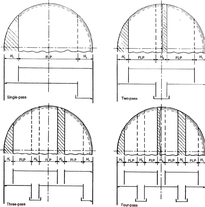
See Figure 18.8 for allocation of down comers in multi pass trays.
Step 12. Calculate the actual FPL from the equation:
FPL =
12 × DT − (2H
1
+ H
3
+ 2H
5
+ 2H
7
)
NP
where
H
1–7
are individual down comer widths in ins (see Figure 18.8)
NP = number of passes.
Step 13. Calculate actual active area (AA) using values for H calculated in step 12
and Table 18.A.1 in the Appendix to establish inlet areas of multi pass tray down
comers.
892 CHAPTER 18
Figure 18.8. Types of tray.
AA = AT − (2AD
1
+ AD
3
+ 2AD
5
+ 2AD
7
)
where
AA = Actual active area in sqft.
AT = actual tower area in sqft.
AD
1–7
are individual down comer areas in sqft for multi pass trays corresponding
to H
1−7
.
Step 14. From the data now developed calculate the actual percent of flood or flood
factor (FF).

PROCESS EQUIPMENT IN PETROLEUM REFINING 893
The following expression is used for this:
% Flood =
V
l
+ (L × FPL/13,000) × 100
AA × CAF
Step 15. Calculate vapor hole velocity V
h
assume 12–14 units (holes) per sqft of AA.
Then
V
h
=
CFS × 78.5
NU
where
V
h
= Hole velocity in ft/sec.
CFS = Actual cuft/sec of the vapor.
NU = Total number of units.
Step 16. Calculate dry tray pressure drops from:
Valves partly open: P
D
= 1.35 t
m
ρ
m
/ρ
l
+ K
1
(V
h
)(ρ
v
/ρ
l
)
where
P
D
= dry tray valve pressure drop in ins liquid
t
m
= valve thickness in ins (see Table 18.4)
ρ
m
= valve metal density in lbs/cuft (see Table 18.4)
K
1
= pressure drop coefficient (see Table 18.4)
Valves fully open: P
D
= K
2
(V
h
)
2
ρ
v
/ρ
l
where K
2
= pressure drop coefficient (see Table 18.4).
Table 18.4. Pressure drop coefficients (Glitch Ballast Type Trays)
䉳
←−−−−−−K
2
for deck thickness (ins)−−−−−−→
䉴
Type of Unit K1 0.074 0/104 0.134 0.25
V1 0.2 1.05 0.92 0.82 0.58
V4 0.1 0.68 0.68 0.68 ——
䉳
←−−−Thickness−−−→
䉴䉳
←−−−Densities of valve material−−−→
䉴
Gauge tm ( ins) Metal Density (lbs/cuft)
20 0.37 CS 400
18 0.5 SS 500
16 0.6 Ni 553
14 0.074 Monel 550
12 0.104 Titanium 283
10 0.134 Hasteloy 560
Aluminum 168
Copper 560
Lead 708
894 CHAPTER 18
Step 17. Calculate total tray pressure drop.
P = P
D
+ 0.4(L/L
wi
)
0.87
+ 0.4H
w
where
P = total tray pressure drop in ins of liquid.
L
wi
= weir length in ins (from Chapter 3 Appendix Figure A4.0).
H
w
= weir height in ins (usually 1–2).
Step 18. Calculate height of liquid in down comer.
First calculate the head loss under the down comer H
UD
, where H
UD
= 0.65(V
UD
)
2
.
V
UD
is calculated from the liquid velocity in CFS or gpm/450 divided by the
area under the down comer. Use weir length times weir height for the area. This
velocity should be around 0.3–0.6 ft/sec for most normal towers.
Then:
H
dc
= H
w
+ 0.4(L/L
wi
)
.67
+ (P + H
UD
)(ρ
l
/(ρ
l
− ρ
v
)).
where
H
dc
=height of liquid in down comer in ins
For normal design this should not exceed 50% of tray spacing.
An example calculation now follows:
Example calculation
In this example the same Liquid and Vapor flows and data will be used as used in the
‘Quickie Calculation’. The objective of this calculation will be to determine the tower
diameter, tray pressure drop and configuration and the percent flood for the design
flow rates given.
Calculating the down comer design velocity V
dc
System factor in this case is 1.
V
dc
= 250 × 1.0 = 250
or V
dc
= 41 × (ρ
1
− ρ
v
) × 1.0
= 41 × 5.06 ×1.0 = 207
or V
dc
= 7.5 × TS ×(ρ
1
− ρ
v
) × 1.0
= 7.5 × 4.9 ×5.06 = 186 (TS = tray spacing = 24
)
or V
dc
= 188 from Figure 18.5, use V
dc
= 186 gpm/sqft.
Vapor capacity factor CAF.
System factor in this case is 1.
From Figure 18.6 CAF = 0.43.

PROCESS EQUIPMENT IN PETROLEUM REFINING 895
Actual vapor load V
l
.
V
l
= CFS
ρ
v
/(ρ
l
− ρ
v
)
= 7.83
1.69/(27.3 − 1.69)
= 2.01.
Approximate tower diameter AT.
Using Figure 9.7 V
l
= 2.01
TS = 24
L = 153 gpm
Tower id = 3.25 ft = 39
Area = 8.30 sqft.
Calculate approx flow path length FPL.
FPL =
9 × 39
No of passes
× 12 = 29.25 ins.
Calculate minimum active area AA
m
.
AA
m
=
V
1
+ (L × FPL/13,000)
CAF × FF
=
2.01 + (153 × 29.25/13,000)
0.43 × 0.8
(using 80% flood)
= 3.01 sqft.
Calculating minimum down comer area AD
m
.
AD
m
=
L
V
dc
× 0.8
=
153
186 × 0.8
= 1.028 sqft.
Calculating the minimum tower cross-sectional area.
Either AA
m
+ 2AD
m
= 3.01 + 2.056
= 5.066 sqft.
or
V
1
0.78 × CAF × 0.8
= 7.49 sqft
Use the larger which is 7.49 sqft.
