Jones D.S.J., Pujado P.R. Handbook of Petroleum Processing
Подождите немного. Документ загружается.

SUPPORT SYSTEMS COMMON TO MOST REFINERIES 593
pilot opens reducing the pressure on top of the piston and the main valve goes fully
open.
Resilient seated safety relief valves
When metal-to-metal seated conventional or bellows type safety relief valves are
used where the operating pressure is close to the set pressure, some leakage can be
expected through the seats of the valve (Refer to API Standard 527, “Commercial
Seat Tightness of Safety Relief Valves with Metal-to-Metal Seats”).
Resilient seated safety relief valves with either O-Ring seat seal or plastic seat such as
Teflon provide seat tightness. Limitations of temperature and chemical compatibility
of the resilient material must be considered when using these valves.
Rupture disk
A rupture disk consists of a thin metal diaphragm held between flanges. The disk
is designed to rupture and relieve pressure within tolerances established by ASME
Code.
Capacity
The maximum amount of material to be released during the largest single risk emer-
gency determines the size of the safety relief valves in any given system. Any calcu-
lation to determine valve sizing must therefore be preceded by a calculation or some
determination of the maximum amount. Among the most common sizing criteria is
the event of fire and its effect on the contents of exposed vessels. There are also other
criteria which can determine maximum release that are attributable to operational
failure.
Capacity due to fire
The exact method of making this calculation must be established from the appropriate
codes which apply, API RP-520, Part I, API Standard 2510, NFPA No. 58, or local
codes which may apply. Each of the listed codes or standards approach the problem
in a slightly different manner.
Liquid systems—A majority of the systems that are encountered will contain liquids
or liquids in equilibrium with vapor. Fire relief capacity in this situation is calculated
on the basis of heat energy from the fire translated in terms of vapor generated in the
boiling liquid.
594 CHAPTER 13
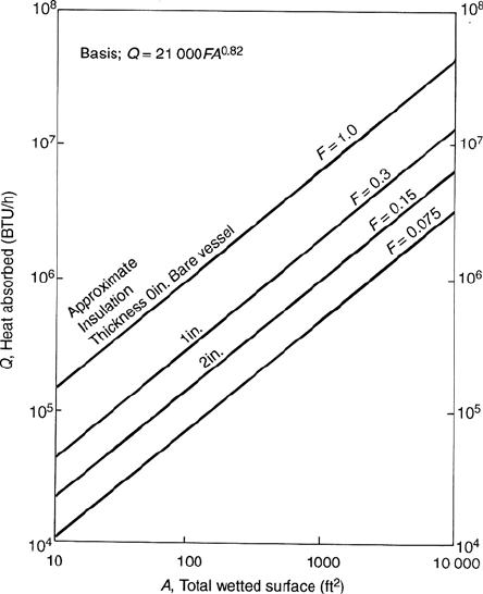
Figure 13.39. Insulation factors.
API RP-520, Part I, applies to refineries and process plants. It expresses requirements
in terms of heat input.
Q = 21000FA
0.82
where
Q = Btu/hr heat input
A = area in sqft of wetted surface of the vessel up to 25 ft above grade.
Wetted surface is calculated at the maximum fill level. Grade is the ground
level under the vessel.
F = fireproof factor due to insulation becoming 1.0 for a bare vessel (see Figure
13.39).
The amount of vapor generated with this is then calculated from the latent heat of the
material at the relieving pressure of the valve by the following equation. For fire relief
only this may be calculated at 120% of maximum allowable working pressure. All
SUPPORT SYSTEMS COMMON TO MOST REFINERIES 595
other conditions must be calculated at 110% of maximum allowable working pressure
thus:
Q/H
t
= W
where
Q = Btu/hr heat input to the vessel
H
L
=Btu/lb latent heat of the material being relieved
W = lb/hr of vapor to be relieved by the relief valve
The latent heat of pure and some mixed paraffin hydrocarbons materials may be
estimated using the data given in API RP-520. A more accurate latent heat evaluation
for mixed hydrocarbons will be found by utilizing vapor-liquid equilibrium K data and
making a flash calculation. Mixed hydrocarbons will fractionate, beginning with the
lowest temperature boiling mixture and progress to the highest temperature mixture;
therefore, consideration must be given to the condition which will cause the largest
vapor generation requirements from the heat input of a fire.
Latent heat will approach a minimum value near critical conditions; however, the
effect does not go to zero. An arbitrary minimum value that may be used is 50 Btu/lb.
Sizing of required orifice areas
The safety relief valve manufacturers have standard orifice designation for area and
the valve body sizes which contain these orifices (API Standard 526, “Flanged Steel
Safety Relief Valves for Use in Petroleum Refineries”). The standard orifices available,
by letter designation and area are:
D Orifice 0.110 inch
2
E Orifice 0.196 inch
2
F Orifice 0.307 inch
2
G Orifice 0.503 inch
2
H Orifice 0.785 inch
2
J Orifice 1.287 inch
2
K Orifice 1.838 inch
2
L Orifice 2.853 inch
2
M Orifice 3.60 inch
2
N Orifice 4.34 inch
2
P Orifice 6.38 inch
2
Q Orifice 11.05 inch
2
R Orifice 16.0 inch
2
T Orifice 26.0 inch
2
Note: however, many small safety relief valves are manufactured with orifice areas
smaller than “D”, and many pilot-operated types contain orifice areas larger than “T”.

596 CHAPTER 13
Sizing for gas or vapor relief, sonic or critical flow
Safety relief valves in gas or vapor service may be sized by use of one of these
equations:
A =
W
√
T
√
Z
CKP
i
K
b
√
M
A =
V
√
T
√
M
√
Z
6.32 CKP
i
K
b
A =
V
√
T
√
G
√
Z
1.175 CKP
i
K
b
where
W = flow through valve, lb/hr
V = flow through valve, scfm
C =coefficient determined by the ratio of the specific heats of the gas or vapor at
standard conditions
K = coefficient of discharge, obtainable from the valve manufacturer (usually
0.6–0.7).
A = effective discharge area of the valve, inch
2
P
i
=upstream pressure, psia. This is set pressure plus overpressure plus the
atmospheric pressure
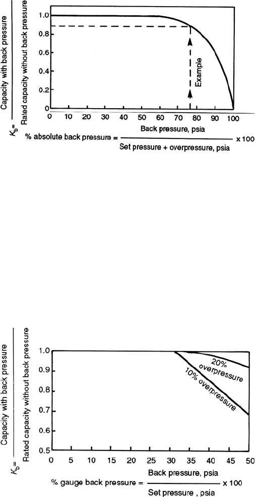
K
b
=capacity correction factor due to back pressure. This can be obtained from
Figure 13.40 for conventional valves or pilot operated valves, and from
Figure 13.41 for balanced bellows valves
M =molecular weight of gas or vapor
T = absolute temperature of the inlet vapor in
◦
R(
◦
F + 460)
Z = compressibility factor for the deviation of the actual gas from a perfect
gas.
G = specific gravity of gas referred to air = 1.00 at 60
◦
F and 14.7 psia
Sizing for liquid relief
Conventional and balanced bellows safety relief valves in liquid service may be sized
by use of the following equation. Pilot-operated relief valves should be used in liquid
service only after determining from the manufacturer that they are suitable for the
service.
A =
gpm
√
G
38K (K
p
K
w
K
v
)(1.25P − P
b
)
1/2
SUPPORT SYSTEMS COMMON TO MOST REFINERIES 597
Figure 13.40. Back pressure sizing factor K
b
for conventional valves.
Note: A coefficient of discharge of 0.62 is normally used for K .
where
gpm = flow rate at the selected percentage of overpressure, in US gals
A = effective discharge area, inch
2
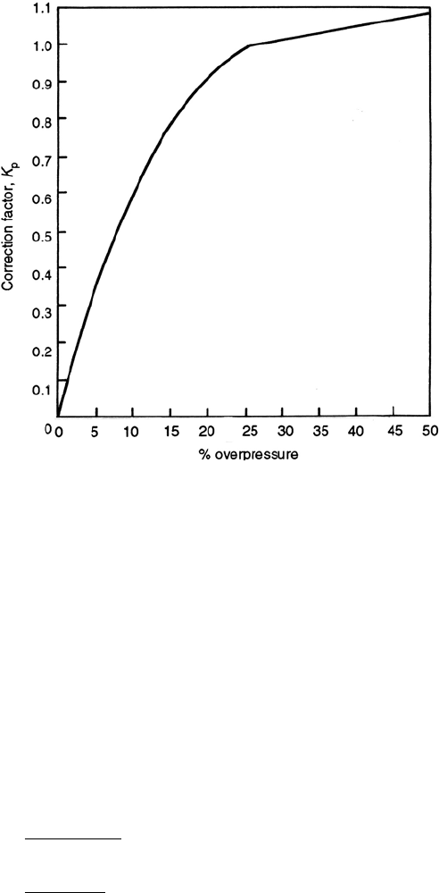
K
p
=capacity correction factor due to overpressure. For 25% overpressure
K
p
= 1.00. The factor for other percentages of overpressure can be
obtained from Figure 13.42
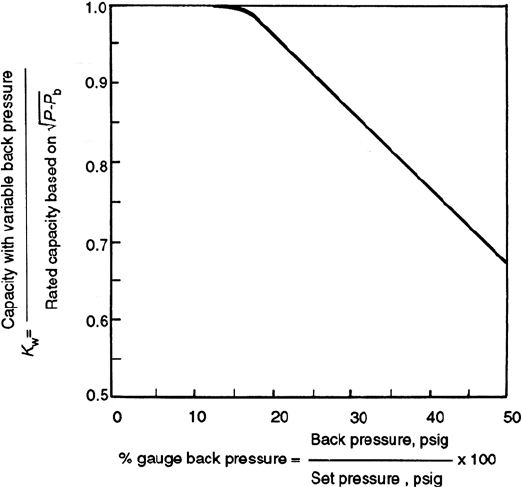
K
w
=capacity correction factor due to back pressure and is required only when
balanced bellows valves are used. K
w
can be obtained from Figure 13.43
Figure 13.41. Back pressure sizing factor K
b
for balanced valves.
598 CHAPTER 13
Figure 13.42. Capacity correction factor due to over pressure K
p
.
K
v
=capacity correction factor due to viscosity. For most applications, viscosity
may not be significant, in which case K
v
= 1.00. When viscous liquid is
being relieved see method of determining K
v
as described below.
P =set pressure at which relief valve is to begin opening, psig
P
b
=back pressure, psig
G = specific gravity of the liquid at flowing temperature referred to water
= 1.00 at 70
◦
F.
When a relief valve is sized for viscous liquid service, it is suggested that it be sized
first as for non-viscous-type application in order to obtain a preliminary required
discharge area, A. From manufacturers’standard orifice sizes, the next larger orifice
size should be used in determining the Reynold’s number, R, from either of these
relationships:
R =
gpm (2800G)
µ
√
A
R =
12700 gpm
U
√
A
SUPPORT SYSTEMS COMMON TO MOST REFINERIES 599
Figure 13.43. Capacity correction factor K
w
.
where
gpm =flow rate at the flowing temperature, in US GPM
G = specific gravity of the liquid at the flowing temperature referred to water =
1.00 at 70
◦
F
µ =absolute viscosity at the flowing temperature, in centipoise.
A = effective discharge area, in sqin (from manufacturers’standard orifice areas)
U =viscosity at the flowing temperature, in Saybolt Universal seconds
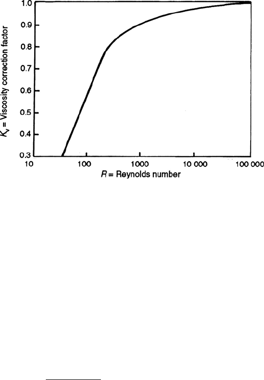
After the value of R is determined, the factor K
v
is obtained from Figure 13.44. Factor
K
v
is applied to correct the “preliminary required discharge area.”If the corrected area
exceeds the “chosen standard orifice area,”the above calculations should be repeated
using the next larger standard orifice size.
Sizing for mixed-phase relief
When a safety relief valve must relieve both liquid and gas or vapor it may be sized
by the following steps:
(a) Determine the volume of gas or vapor and the volume of liquid that must be
relieved.
600 CHAPTER 13
Figure 13.44. Capacity correction factor due to viscosity K
v
.
(b) Calculate the orifice area required to relieve the gas or vapor as previously outlined.
(c) Calculate the orifice area required to relieve the liquid as previously outlined.
(d) The total required orifice area is the sum of the areas calculated for liquid and
vapor.
Sizing for flashing liquids
The conventional method is to determine the percent flashing from a Mollier diagram
or from the enthalpy values. Then consider the liquid portion and vapor portion
separately as in mixed phase flow. A method to calculate the percent flashing is
shown in the following equation:
% Flash =
h
f
(1) − h
f
(2)
h
fg
(2)
× 100
where
h
f
(1) =enthalpy in Btu/lb of saturated liquid at upstream temperature
h
r
(2) =enthalpy in Btu/lb of saturated liquid at downstream pressure
h
fg
(2) =enthalpy of evaporation in Btu/lb at downstream pressure
Sizing for gas or vapor on low-pressure sub-sonic flow
When the set pressure of a safety relief valve is very low, such as near atmospheric
pressure, the K
b
values obtainable from Figure 13.40 are not accurate. Safety relief
SUPPORT SYSTEMS COMMON TO MOST REFINERIES 601
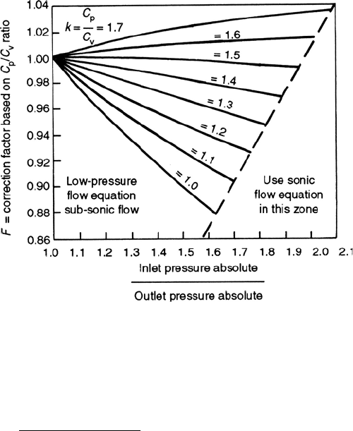
Figure 13.45. Flow correction factor ‘F ’based on specific heats.
valve orifice areas for this low-pressure range may be calculated:
A =
Q
v
√
GT
863KF
√
(P
1
− P
2
)P
2
where
A = effective discharge area of the valve, inch
2
Q
v
=flow through valve, scfm
G = specific gravity of gas referred to air = 1.00 at 60
◦
F and 14.7 psia
T = absolute temperature of the inlet vapor,
◦
R =
◦
F + 460
K = coefficient of discharge, is available from the valve manufacturer
F = correction faction based on the ratio of specific heats. This can be obtained
from Figure 13.45.
P
1
=upstream pressure in psia = set pressure plus overpressure plus atmospheric
pressure
P
2
=downstream pressure at the valve outlet in psia
An example calculation covering the sizing of a relief valve is given in Appendix 13.2
of this chapter.
602 CHAPTER 13
Appendix 13.1: Example calculation for sizing a tank heater
Problem
It is required to calculate the surface area for a heating coil which will maintain the
bulk temperature of fuel oil in a cone roofed tank at a temperature of 150
◦
F. The
ambient air temperature is an average 65
◦
F and the wind velocity averaged over the
year is 30 MPH. The fuel oil data is as follows:
Viscosity (µ) = 36 cps @ 150
◦
F
Sg @ 150
◦
F = 0.900
The tank is to be heated with 125 psig saturated steam. The tank dimensions are 60 ft
diameter ×180 ft high it is not insulated but is painted with non metallic color paint.
Solution
1.0 Calculating the heat loss from the wall.
1st trial. Assume wall temperature is 120
◦
F
h
i
= 8.5(t
i
/µ)
0.25
where
t
i
=150 − 120 = 30
◦
F
h
i
=8.5 × 0.955 = 8.12 Btu/hr. sqft.
◦
F
‘a’ = 8.12 × 30 = 243.6 Btu/hr. sqft.
t
o
is temperature difference between assumed wall temp and the ambient air =
120 − 65 = 55
◦
F.
h
co
= 0.495 × 1.3 (from Figure 13.9)
Wind correction factor F
w
is as follows:
F
l
=(MPH/1.47)
0.61
=6.29
F2 =1.04 (From Figure 13.10)
F
w
=6.29 + 1.04
=7.33.
h
co
(corrected) =0.495 × 1.3 × 7.33
=4.20 Btu/hr. sqft.
◦
F
Heat loss from wall due to radiation h
ro
is found from Figure 13.8 =1.18 Btu/hr.sqft.
◦
F.
