Jones D.S.J., Pujado P.R. Handbook of Petroleum Processing
Подождите немного. Документ загружается.


SUPPORT SYSTEMS COMMON TO MOST REFINERIES 563
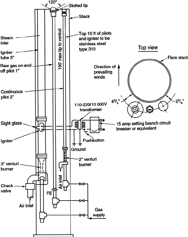
Figure 13.24. Flare top igniter assembly.
are activated when the pressure in the flare header reaches 30 ins of water gauge. Very
often, particularly in large process complexes, the ground flare is designed to operate
in conjunction with an elevated flare. The multi-jet flare takes a gas stream up to say
80% of its rated capacity additional flow is then diverted to an elevated flare system.
Thus, if there is need for the continuous flaring of a reasonably small quantity, the
ground flare caters for it. In an emergency or surge the elevated flare comes into
operation automatically to take the additional load.

564 CHAPTER 13
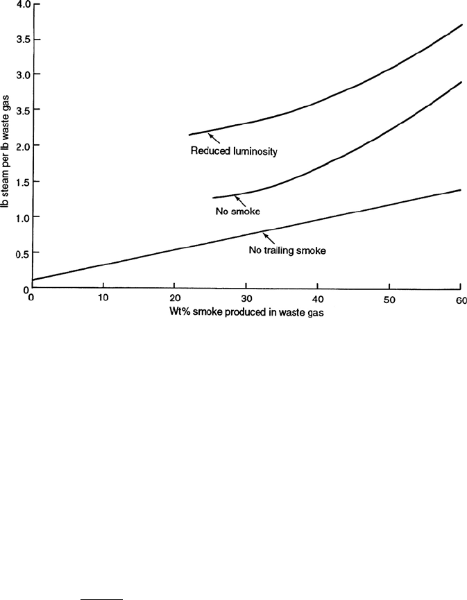
Figure 13.25. Approximate amount of steam for smoke abatement.
The burners of a multi-jet flare are jet nozzles approximately 15 ins in length of 1 ins
diam stainless steel pipe. They discharge vertically from the horizontal burner lines
which run across the bottom of the stack. The number of jets is based on gas velocity
and is expressed by the equation:
N = 16.4V
where
N =number of Jets
V = flare design capacity in mmScf/day.
The jets are placed on a square or rectangular pitch of 18 to 24 ins. A first estimate
of the required pitch may be obtained from the expression:
P =
100 D
2
NC
where
P = pitch in ins
D =stack ID in feet
N =number of jets
C =distance between burner center lines in ins
SUPPORT SYSTEMS COMMON TO MOST REFINERIES 565
No jet should be placed closer than 12 ins to the inside of the stack.
The inside diameter of the stack is based on the rate of heat release at design capacity.
It is calculated using the following equation:
D = 0.826Q
5
where
D =stack inside diameter in feet
Q = heat release at max design in mm Btu/hr.
The stack height for diameters up to 25 ft is 32 ft and the steel shell of the stack is
lined with 4
of refractory material. A wind breaker completes the construction of the
stack. This is necessary to prevent high wind gusts from extinguishing the flames.
Flame holders are installed above the burners to prevent the flames ‘riding’up to
the top of the stack. These are simply solid rods of 1
refractory material supported
horizontally above each burner line. The position of these flame holders relative to
the bottom of the stack is critical to the proper operation of the burners. The stack
itself is elevated to allow air for combustion to enter. The minimum space between
grade and the bottom of the stack is set at 6 feet or 0.3D whichever is the larger.
As for any flare a continuous pilot burner is recommended. The proper operation of
this pilot is important with respect to multi-jet type flares because of the danger of
un-burnt flammable material escaping outside the flare at ground level. A gas pilot is
provided at each end of the primary burner to minimize this risk.
Effluent water treating facilities
This section of the “Offsite Systems”deals with the treating of waste water accu-
mulated in a chemical process complex before it leaves the complex. Over the years
requirements for safeguarding the environment have demanded close control on the
quality of effluents discharged from chemical and oil refining plants. This includes
effluents that contain contaminants that can affect the quality of the atmosphere and
those that can be injurious to plant and other life in river waters and the surrounding
seas. Effluent management in the oil industry has therefore acquired a position of
importance and responsibility to meet these environmental control demands.
Water effluents that are discharged from the process and other units are collected
for treating and removal or conversion of the injurious contaminants. In most oil
refineries imported water in the form of ship’s ballast water is also collected on shore
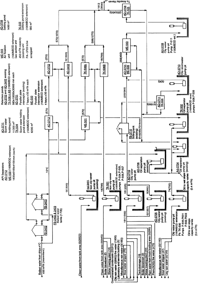
for treatment before discharging back to the sea. Figure 13.26 is a schematic of the
water effluent treating system for a major European oil refinery.

Figure 13.26. A schematic of a water effluent treating system.
SUPPORT SYSTEMS COMMON TO MOST REFINERIES 567
Normally the water effluent treating facilities for a complex would be located at the
lowest geographical point in the plant. In this way very little pumping is required to
move the waste water to and from the treating plants. The schematic in Figure 13.26
is for a refinery that was sited below the sea level so more than the usual number of
pumps are used.
The contaminant that is to be removed in the system shown in Figure 13.26 is, of
course, oil. Five separate systems are used in this refinery’s treatment plant. The first
is that for handling ballast water from sea going tankers. The second is the handling
of clean water. This is included because the system bypasses all the treating processes
except the last “guard”process which, in this case, are the retention ponds. The third
system is also for handling non-oily water but water that would be high in certain
chemicals. This system also discharges into retention or storm water ponds. The water
is held in these ponds to ensure that there is no contamination. Should there be then
the water would be returned into one or the other treating processes for removal of
the contaminants.
The last two systems shown are for the handling of contaminated water from the
refineries paved area, various tank and process plant drainage and the like. These oily
water systems and the ballast water stream are treated for oil removal. In the case
of the ballast water the water drained from the bottom of the holding tanks is routed
through an API separator. This is a specially designed pond that reduces the forward
velocity of the water stream to allow the separation of oil from the water by settling
or gravity.
The water/oil separation for the other refinery streams takes place in a series of
settling pods. Final clean up in this case is accomplished by the use of parallel plate
interceptors and an air flotation process. The principle of the parallel plate interceptor
is to force the water stream to change direction several times in rapid sequence and
thus “knocking out”any oil entrained in the stream. The air flotation unit causes the
contaminated water stream to be agitated so as to force the lighter oil phase to the
surface where it can be removed by skimming or by baffled overflow.
Other treating processes
Most chemical plants and indeed a few oil refining plants require more complex
methods for clarifying their effluent water to meet environmental requirements for its
disposal. The four more common methods are as follows:
r
In-line clarification using coagulation, flocculation and filtration
r
Plain filtration
r
Sedimentation
r
Chemically aided sedimentation using coagulation, flocculation, and settling
568 CHAPTER 13
Clarification is a process that removes suspended (usually organic) matter that gives
the stream color and turbidity. The removal of this matter especially in a colloidal form,
requires the addition of chemicals to cause coagulation and flocculation to promote
settling and separation of suspended solids. Coagulants and coagulant aids added
to the influent stream chemically react with impurities to form precipitates. These,
together with particles of enmeshed turbidity, are flocculated into larger masses that
are then readily separated from the bulk liquid.
There are essentially three steps in the chemically-aided clarification process. These
are:
r
Mixing of the additives
r
Flocculation
r
Settling
Coagulation encompasses the process of mixing the first formation of agglomerates
that form the floc. This is carried out in a series of separate compartments with
the settling basin occupying the largest volume. Coagulation is the singular most
important step in the clarifying process. Because it involves the build up of colloidal
type particles, the chemicals and the process rate are specific to the material that is
to be clarified. There are companies that specialize in the design construction and
the operation of this type of effluent treating. These companies use their experience
in handling the complex electrochemical kinetics associated with flocculation and
coagulation principles.
Utility Systems
All oil refining processes require utilities in order to function. The more common
utility systems are:
r
A steam and condensate system
r
A fuel system
r
Water systems including cooling water, potable water, and boiler feed water (BFW)
r
A compressed air systems
r
A power supply system.
The engineering and design of the first four of these systems is usually the responsi-
bility of a chemical engineer. On operating plants and processes the process engineer
undertakes the responsibility for the correct and efficient operation of utility facilities.
The duties associated with the power systems are usually left to the Electrical Engi-
neer or department, although the process engineer does have an input in the sizing
of the system be developing a list of power requirement for all electrically motivated
equipment. This includes all motors and electrically operated equipment such as: the
desalter, product dehydrators, and the like.
SUPPORT SYSTEMS COMMON TO MOST REFINERIES 569
Brief descriptions of typical utility systems
The following paragraphs describe typical utility systems found in the oil refining
industry. The details of these systems may vary from company to company but their
format and general layout will be as described here. Only the first four systems are
described and discussed here.
Steam and condensate systems
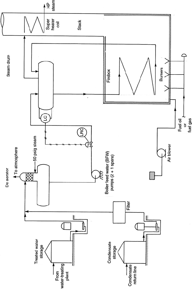
In most plants steam condensate accumulated in the various processes is collected
into a single header and returned to the steam generating plant. It is stored separate
to the treated raw water because condensates may contain some oil contamination. A
stream of treated water and condensate are taken from the respective storage tanks
and pumped to the deaerator drum. The pumps in this case are usually vertical pumps
set in a pit near the storage tanks. The condensate stream passes through a simple
filter on route to the deaerator to remove any oil contamination. The combined water
and condensate streams enter the top of a packed section of the deaerator drum.
Low-pressure steam is introduced immediately below the packing in the drum to
flow upwards countercurrent to the liquid streams. Any air entrained in the water is
removed by this counter current flow of steam to be vented to atmosphere.
The deaerated BFW is pumped by the BFW pumps into the steam drum of the steam
generator. There will normally be three 60% pumps for this service. Two will be
operational and one will be on standby. Those pumps normally operating are usually
motor driven while the standby pump is very often driven by an automatically start
up diesel engine. These pumps are quite large in capacity operating at high head and
discharge pressure. The main steam lines in most plants are high-pressure (at least 700
psig at the generator coil outlet), so the pump discharge pressure will be much greater
than the HP steam outlet. These pumps are the most important in any chemical plant.
If they fail no steam can be generated and the whole complex is in danger of total
shutdown or worse. Therefore three separate pumps are used to cater for the normal
high head and high capacity, and a separate pump driver operating on a completely
different power source than electrical power or steam is mandatory to minimize the
danger of complete shut down.
The steam drum is located above the generator’s firebox. The liquid in the drum flows
through the generator’s coils located in the firebox by gravity and thermo-syphon.
A mixture of steam and water is generated in the coils and flows back to the steam
drum. Here the steam and water are separated with the steam leaving the drum to
enter the super-heater coil. The steam is heated to the plant’s steam main temperature
in this coil and enters the high-pressure steam header for distribution to the various
users. The steam pressure is controlled be a pressure controller on the steam outlet to
570 CHAPTER 13
the header. Steam to the lower pressure headers is generated through turbines where
possible. Where lower pressure steam is required and it is not possible to produce it
through equipment then let down stations are located in suitable places in the system.
When steam pressure is reduced to the lower pressure headers the associated increase
of temperature above that specified for the lower pressure steam may need to be
reduced. Desuperheaters are used for this purpose.
Desuperheaters consist of a chamber in the steam line into which cold condensate
is injected. These items are purchased equipment with specially designed injection
nozzles for the condensate. The amount of condensate delivered is controlled by the
downstream temperature of the steam. Desuperheaters are located at critical locations
of the plant where relatively large quantities of high-pressure steam are reduced to
low pressures such as the discharge from turbines.
The condensate return header is usually operated at a positive pressure of between
5 and 10 psig. The condensate is stored at atmospheric pressure, and very often the
small amount of steam flashed from the header pressure to the storage pressure is
used in the deaerator instead of the low-pressure steam (the deaerator operates at or
near atmospheric pressure).
Figure 13.27 is a schematic flow diagram of a typical steam generation unit.
Fuel systems
Most oil refineries have two separate fuel systems. They have:
r
A fuel gas system
r
And a fuel oil system
The user burners in these plants are of the dual purpose design. They fire either the
fuel gas or the fuel oil stream and can be easily switched over from one to the other.
The pilot burners however must be fuel gas, and the system is designed such that if
the pilot burner is extinguished the whole burner system is shutdown. Generally the
design of the burner system in most plants have many safety and shutdown features.
After all in processes that handle flammable material the heater burners are the one
feature in the plant design that are a major fire hazard source. Thus the design of the
burner operation is such as to shutdown on:
r
Low fuel pressure
r
High process outlet temperature
r
Pilot burner extinguished
r
Atomizing steam failure (oil burners)
r
Low process feed to heater

Figure 13.27. A typical steam generation unit.
572 CHAPTER 13
Fuel gas system
This is the simplest of the two systems. Waste gas streams from the process plants are
gathered and directed to the plant’s fuel gas drum. This drum operates at 30 psig pres-
sure and close to ambient temperature or 60
◦
F. A small steam coil is usually installed
in the drum to gasify any “below dew point”material that may have condensed out.
The drum is held at the set pressure by pressure control valves which allows surplus
gas to flow to flare and activates an emergency source of gas on low pressure. This
emergency source may be in the form of imported liquefied petroleum gas (LPG) or
some other plant gas stream that may be diverted to fuel. If LPG is used as a secondary
fuel source it is routed to the fuel gas drum via a vaporizer. This item of equipment is
a kettle type re-boiler heating and vaporizing the LPG at the drum pressure. Medium
or low-pressure steam is used as the heating medium for the vaporizer.
The gas burner at the process fired heater operates at or close to atmospheric pressure.
The burner draws fuel from a separate header than that used to supply gas to the pilot
burner. Many heaters contain an automatic switch over from gas firing to fuel oil firing
on low gas flows or when manually selected. The fuel gas system is “dead ended”.
That is there is no return system to the fuel gas drum, the gas header is pressured up
and gas flows to the burners by means of this differential pressure and intermediate
control valves. The fuel gas flow to the heater burners is controlled by a temperature
control valve activated by a temperature controller on the heater coil process outlet
line. The same controller also regulates the oil firing arrangement when the heater is
operated on fuel oil.
Fuel oil system
Figure 13.28 is a schematic of a typical fuel oil system. Most plants use petroleum
residues as fuel oil. These types of fuel are high in viscosity and very often have a high
pour point. (Pour point temperature is the temperature that the oil ceases to flow.) For
this reason the fuel oil is stored in insulated and heated cone roofed tanks. Heating
may be accomplished by steam coils located in the base of the tank or by external
steam heat exchanger through which the fuel oil is continually circulated.
Positive displacement pumps (usually rotary type) are used to deliver the fuel oil
from the tank, through the distribution system to the heater burners. These pumps are
always spared and the spare pump is driven by a steam turbine, while the operating
pump is motor driven. The fuel oil passes through a duplex filter before entering the
suction of the pumps. This filter is included to remove any solid contaminants that
may be in the oil such as fine coke particles which would foul the fuel oil burner.
The discharge pressure of the pumps is controlled by a slipstream routed back to the
storage tanks through a pressure control valve. This valve is activated by a pressure
control element on the pump discharge header.
