Jones D.S.J., Pujado P.R. Handbook of Petroleum Processing
Подождите немного. Документ загружается.

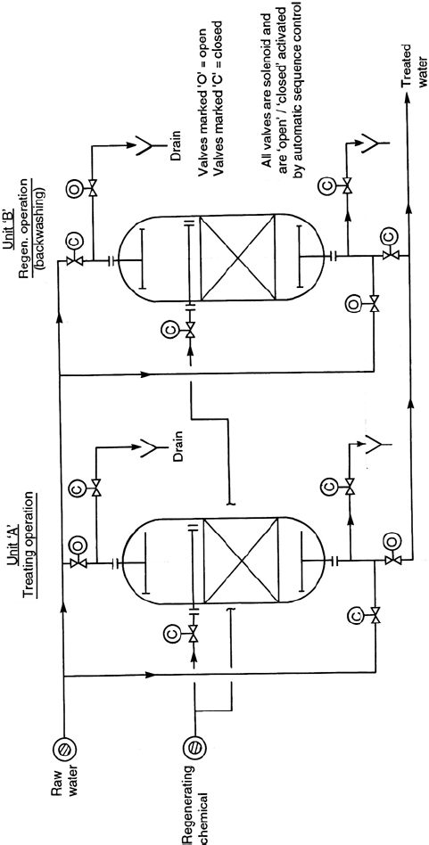
Figure 13.34. An ion exchange unit hook up.
584 CHAPTER 13
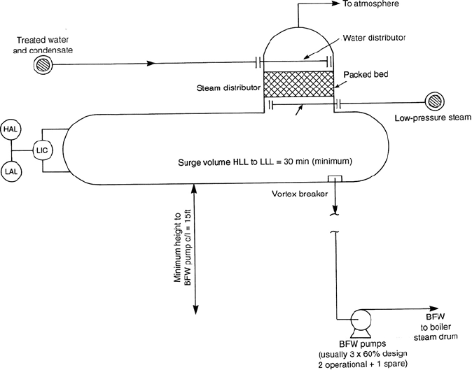
Figure 13.35. A deaerator drum.
counter current to the water. This action removes the dissolved gasses from the water.
These gasses then leave with the steam from the top of the degassing section to be
vented to atmosphere. The gas free water free flows into the main retaining section
of the deaerator.
The treated water feed is introduced to the degassing section of the deaerator through
atomizing spray/distributor. This reduces the water stream to fine droplets prior to
entering the packed section. This enhances the removal of the gasses in the water.
deaerators operate at about 2–3 psig and at this pressure all of the CO
2
contained in
the water and most of the oxygen is removed.
The BFW pumps draw suction directly from the deaerator. To ensure that there is
available sufficient NPSH for the pumps to operate properly deaerator drums are
installed on a structure at least 15 ft above the center line of the pump suction.
Most large pumps (as BFW pumps are) usually require a relatively high NPSH when
handling hot water.
The retention section of the deaerator should have as a minimum 30 minutes of surge
between HLL and LLL. The water feed to the deaerator is normally on retention
SUPPORT SYSTEMS COMMON TO MOST REFINERIES 585
section level control. The boiler feed from the BFW pumps will be on flow control
with steam drum level reset. Very often boiler feed flow has low flow alarm and at
very low flow has automatic boiler shut down device.
Compressed air system
All oil refining plants require a supply of compressed air to operate the plant and for
plant maintenance. There are usually two separate systems and these are:
r
Plant air system
r
Instrument air system
Plant air is generally supplied by a simple compressor with an after cooler. Very often
when plant air is required only for maintenance this is furnished by a mobile compres-
sor connected to a distribution piping system. Air for catalyst regeneration and the like
is normally supplied by the regular process gas compressor on the unit. Instrument air
should always be a separate supply system. Compressed air for instrument operation
must be free of oil and dry for the proper function of the instruments it supplies. This
is a requirement which is not necessary for most plant air usage. A reliable source
of clean dry instrument air is an essential requirement for plant operation. Failure of
this system means a complete shut down of the plant.
Figure 13.36 shows a typical instrument air supply system.
Atmospheric air is introduced into the suction of one of two compressors via an
air filter. The compressors are usually reciprocating or screw type non-lubricating.
Centrifugal type compressors have been used for this service when the demand for
instrument air is very high. The air compressors discharge the air at the required
pressure (usually above 45 psig) into an air cooler before the air enters one of two
dryers. One of the compressors is in operation while the other is on standby. The
operating compressor is usually motor driven with a discharge pressure operated
on/off start up switch. The standby compressor is turbine (or diesel engine) driven
with an automatic start up on low discharge pressure switch.
The cooled compressed air leaves the cooler to enter the dryers. There are two dryer
vessels each containing a bed of desiccant material. This material is either silica
gel (the most common), alumina, or in special cases zeolite (molecular sieve). One
of the two dryers is in operation with the compressed air flowing through it to be
dried and to enter the instrument air receiver. The desiccant in the other dryer is
being simultaneously regenerated. Regeneration of the desiccant bed is effected by
passing through the bed a stream of heated air and venting the stream to atmo-
sphere. This heated stream removes the water from the desiccant to restore its hy-
groscopic properties. At the end of this heating cycle cooled air is reintroduced to
cool down the bed to its operating temperature. When cool the unit is ready to be
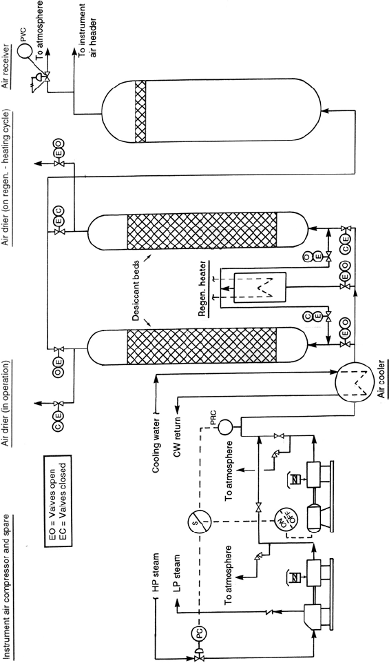
Figure 13.36. An instrument air supply system.
SUPPORT SYSTEMS COMMON TO MOST REFINERIES 587
switched into operation for the first dryer to start its regeneration cycle. The various
operating and regeneration phases are automatically obtained by a series of solenoid
valves operated by a sequence timer switch control. These dryers (often including the
compressor and receiver items) are packaged units supplied, skid mounted, and ready
for operation.
The instrument air receiver vessel is a pressure vessel containing a crinkled wire mesh
screen (CWMS) before the outlet nozzle. It is high-pressure protected by a pressure
control valve venting to atmosphere, and of course is also protected by a pressure
safety relief valve (not shown in diagram). The air leaves the top of this vessel to
enter the instrument air distribution system servicing all the plants in the complex.
13.3 Safety systems
A major requirement in the design and engineering of a plant or system is to ensure its
safe operation. Much of the effort in this respect is directed to determining the pressure
limits of equipment and to protect that equipment from dangerous over pressuring.
Pressure relief valves are normally used for this protection service, although under
certain conditions bursting discs may be used. This section of Chapter 13 covers the
various types of relief valves, and the procedure for calculating the correct orifice size
of the valve and the valve selection.
Determination of risk
The cost of providing facilities to relieve all possible emergencies simultaneously is
prohibitive. Every emergency arises from a specific cause, the simultaneous occur-
rence of two or more emergencies or contingencies is unlikely. Hence, an emergency
which can arise from two or more contingencies (e.g., the simultaneous failure of
a control valve and cooling water) is not considered when sizing safety equipment.
Likewise, simultaneous but separate emergencies are not considered.
Every unit or piece of equipment must be studied individually and every contingency
must be evaluated. The safety equipment for an individual unit is sized to handle the
largest load resulting from any possible single contingency. If a certain emergency
would involve more than one unit, then all must be considered as an entity. The
equipment judged to be involved in any one emergency is termed “single risk”. The
single risk which results in the largest load on the safety facilities in any system is
termed “largest single risk”and forms the design basis for the equipment.
Note: The emergency which results in the largest single risk on the overall basis may
be different from the emergency(ies) which form the basis for individual pieces of
equipment.
588 CHAPTER 13
Contingencies generally fall into one of two categories—fire (external) or operating
failure. Operating failure covers such contingencies as utility failure, mechanical
failure, or mal-operation.
Definitions
The terms used and the descriptions given in this item are based on data given in two
API publications. These are: API RP520 and 521. References are also made to: Part 1
ANSI Proposed Standard, “Terminology for Pressure Relief Devices”and to ASME
PTC 25.2. These publications are the safety standards commonly in current use. The
following definition of terms used in the design of safety systems helps to understand
the design and criteria of safety systems.
Accumulation
Accumulation is the pressure increase over the maximum allowable working pressure
of the vessel during discharge through the pressure relief valve expressed as a percent
of that pressure, or in PSI.
Atmospheric discharge
Atmospheric discharge is the release of vapors and gases from pressure relief and
de-pressurizing devices to the atmosphere.
Back pressure
Back pressure is the pressure existing at the outlet of the pressure relief device due to
pressure in the discharge system.
Balanced safety relief valves
A balanced safety relief valve incorporates means for minimizing the effect of back
pressure on the performance characteristics-opening pressure, closing pressure, lift,
and relieving capacity.
Blow-down
Blow-down is the difference between the set pressure and the resealing pressure of a
pressure relief valve, expressed as a percent of the set pressure, or in PSI.
SUPPORT SYSTEMS COMMON TO MOST REFINERIES 589
Burst pressure
Burst pressure is the value of inlet static pressure at which a rupture disk device
functions.
Conventional safety relief valve
A conventional safety relief valve is a closed bonnet pressure relief valve that has the
bonnet vented to the discharge side of the valve. The performance characteristics-
opening pressure, closing pressure, lift, and relieving capacity are directly affected
by changes of the back pressure on the valve.
Design pressure
Design pressure is the pressure used in the design of a vessel to determine the minimum
permissible thickness or physical characteristics of the different parts of a vessel.
Flare
A flare is a means for safe disposal of waste gases by combustion. With an elevated
flare the combustion is carried out at the top of a pipe or stack where the burner and
igniter are located. A ground flare is similarly equipped except that combustion is
carried out at or near ground level. A burn pit differs from a flare in that it is normally
designed to handle both liquids and vapors. Flare systems are described and discussed
more fully in “Offsite Systems”of this chapter.
Lift
Lift is the actual travel of the disk away from closed position when the valve is
relieving.
Overpressure
Overpressure is the pressure increase over the set pressure of the primary relieving
device; it would be termed accumulation when the relieving device is set at the
maximum allowable working pressure of the vessel.
Note: When the set pressure of the first (primary) pressure relief valve to open is less
than the maximum allowable working pressure of the vessel, the overpressure may be
greater than 10% of the set pressure of the valve.
590 CHAPTER 13
Pilot-operated pressure relief valve
A pilot-operated pressure-relief valve is one that has the major flow device combined
with and controlled by a self-actuated auxiliary pressure relief valve. This type valve
does not utilize an external source of energy.
Pressure relief valve
Pressure relief valve is a generic term applied to relief valves, safety valves, or safety
relief valves.
Relieving conditions
Relieving conditions pertain to pressure relief device inlet pressure and temperature
at a specific overpressure. The relieving pressure is equal to the valve set pressure
(or rupture disk burst pressure) plus the overpressure. The temperature of the flowing
fluid at relieving conditions may be higher or lower than the operating temperature.
Set pressure
Set pressure in psig is the inlet pressure at which the pressure relief valve is adjusted
to open under service conditions. In a safety or safety relief valve in gas, vapor, or
steam service, the set pressure is the inlet pressure at which the valve pops under
service conditions. In a relief or safety relief valve in liquid service, the set pressure
is the inlet pressure at which the valve starts to discharge under service conditions.
Superimposed back pressure
Superimposed back pressure is static pressure existing at the outlet of a pressure relief
device at the time the device is required to operate. It is the result of pressure in the
discharge system from other sources. This type of back pressure may be constant or
variable; it may govern whether a conventional or balanced-type pressure relief valve
should be used in specific applications.
Vapor depressing system
A vapor depressing system is a protective arrangement of valves and piping intended
to provide for rapid reduction of pressure in equipment by release of vapors. Actuation
of the system may be automatic or manual.
Vent stack
A vent stack is the elevated vertical termination of a disposal system which discharges
vapors into the atmosphere without combustion or conversion of the relieved fluid.
SUPPORT SYSTEMS COMMON TO MOST REFINERIES 591
Types of pressure relief valves
The following is a list of those types of relief valves commonly used in industry. These
have been approved according to ASME V111 “Boiler and Pressure Vessel”code.
Conventional safety relief valves
In a conventional safety relief valve the inlet pressure to the valve is directly opposed
by a spring closing the valve, the back pressure on the outlet of the valve changes the
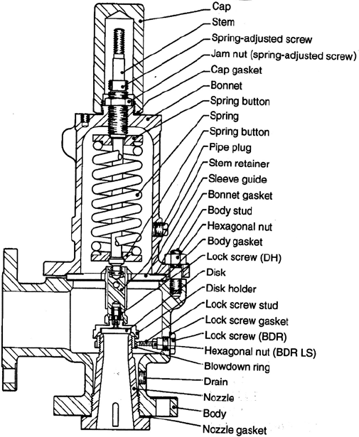
inlet pressure at which the valve will open. A diagram of a conventional relief valve
is shown below as Figure 13.37.
Balanced safety relief valves
Balanced safety valves are those in which the back pressure has very little or no
influence on the set pressure. The most widely used means of balancing a safety relief
Figure 13.37. A diagram of a conventional safety relief valve.
592 CHAPTER 13
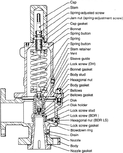
Figure 13.38. A diagram of a balanced safety relief valve.
valve is through the use of a bellows. In the balanced bellows valve, the effective area
of the bellows is the same as the nozzle seat area and back pressure is prevented from
acting on the top side of the disk. Thus the valve opens at the same inlet pressure
even though the back pressure may vary. A diagram of a balanced safety relief valve
is shown as Figure 13.38.
Pilot operated safety relief valves
A pilot-operated safety relief valve is a device consisting of two principal parts,
a main valve and a pilot. Inlet pressure is directed to the top of the main valve
piston, and with more area exposed to pressure on the top of the piston than on the
bottom; pressure, not a spring, holds the main valve closed. At the set pressure the
