Jones D.S.J., Pujado P.R. Handbook of Petroleum Processing
Подождите немного. Документ загружается.

SUPPORT SYSTEMS COMMON TO MOST REFINERIES 523
r
Protecting equipment from damage caused by flow failures
r
Protecting downstream processes from fluctuating flows which could cause poor
process performance
r
Protecting downstream processing from fluctuations in feed composition or tem-
perature
r
Protecting equipment from damage due to coolant failure
Types of surge volumes
There are basically two types of Surge Volumes. These are:
1. Upstream protection surge. This is a surge volume provided to protect the upstream
equipment and its associated pump from feed failure.
2. Downstream flow surge. This is surge volume provided to protect downstream
equipment from feed failures or fluctuations.
Examples of surge types
Process feed. Feed to process units is almost invariably on flow control. Many units
also have a feed surge drum, particularly those units that are sensitive to flow fluctua-
tions or where complete flow failure can cause equipment damage. This is an example
of “downstream flow surge”. The surge volume of the drum will depend on
r
Source and reliability of source
r
Type of control at source
r
Variations and fluctuations in source rate
Column feed from an upstream column. This feed stream will usually be controlled by
the level in the source column, hence it will be fluctuating. If surge volume is provided
only in the source column it must be sufficient to cater for “upstream protection”and
“downstream protection”. The use of a surge vessel would be recommended for this
case.
Feed to fired heaters or boilers. The failure of flow through the tubes of fired heaters
or steam boilers can cause serious damage through overheating of the tubes. Conse-
quently “downstream protection”is required in this case. Invariably flows to heaters
are on flow control.
Reflux drums
1.0 When the drum only furnishes reflux or reflux and product to storage all that is
needed in terms of surge volume is sufficient to provide “upstream protection”.
That is the surge volume required is only to protect the reflux pump from losing
524 CHAPTER 13
suction in the case of column feed failure. The pump will be required to circulate
reflux and cool the column down during an orderly shut down period.
2.0 When the reflux drum furnishes reflux and the feed stream to another unit then
the drum must furnish “upstream protection”surge and “downstream protection”
surge.
3.0 If there is a vapor product from the drum additional volume must be provided
in the drum to allow vapor/liquid disengaging. This will be such as to retain the
same liquid surge capacity as described above.
4.0 Should the vapor phase from the reflux drum be routed to the suction of a com-
pressor an even larger volume reflux drum will be required. This is to ensure
complete disengaging of the vapor/liquid. Internal baffles or screens are also
used in the drums vapor outlet section to ensure complete phase separation.
Quantity of surge volume
The amount of surge volume will vary with the various types given above and with
the specific case in question. Sometimes this amount is set by company specifications
or, in the case of engineering contractors, by the client. Generally however the process
engineer will be responsible for setting a safe and economic surge volume. In doing
this the engineer needs to analyze each case in terms of why the surge volume is being
provided then deciding how much based on this answer. Figure 13.1 provides some
guidelines to the amount of surge that should be applied.
Some useful equations used in setting and handling surge volumes.
For surge volume vol cuft = (GPM) (minutes)/7.48
For vessel size:
Diam, D =
3
√
(cuft/2.35) @ L/D = 3
Diam, D =
3
√
(cuft/1.96) @ L/D = 2.5
Diam, D =
3
√
(cuft/1.57) @ L/D = 2.0
For line size:
Diam, D =
3
√
(GPM/25)@velocity = 10 ft/sec
Diam, D =
3
√
(GPM/17)@velocity = 7 ft/sec.
Diam, D =
3
√
(GPM/12)@velocity = 5 ft/sec.
For flow rate:
ft/sec = GPM/450
For approx control valve size:
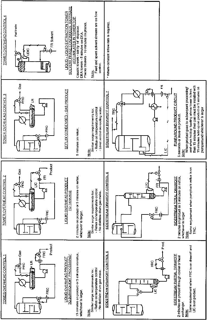
Figure 13.1.
Typical surge requirements.
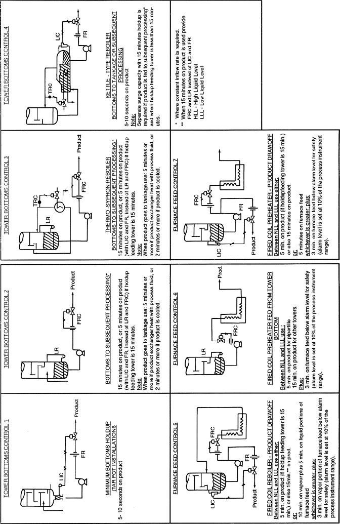
Figure 13.1. (Cont.)
SUPPORT SYSTEMS COMMON TO MOST REFINERIES 527
One size smaller than line size. Thus:
Line CV
4
3
6
4
8
6
10
8
Level control
Surge volumes are maintained by controlling the amount of liquid entering or leaving
the vessel in question. There are several means of accomplishing this and these are
described and discussed in the following paragraphs:
(A) Control the surge liquid outlet on level control. This will give a close level control
but a fluctuating outlet flow. The level control valve (LCV) will close completely at
LLL. Thus flow through the outlet line will be completely shut off at LLL.
(B) Control the surge liquid outlet on flow control and provide a low level alarm.
This will give a fluctuating level but will eliminate flow fluctuations. As there is no
LCV to restrict flow at LLL then operators must physically reset the flow controller to
maintain the surge volume. This has the disadvantage that the alarm condition could
be missed or even ignored, resulting in possible damage to downstream equipment,
and, in extreme cases, result in a fire or explosion hazard.
(C) Control the surge liquid outlet on flow control reset by a level control. This will
give a wandering level but a smooth outlet flow. The LCV reset can still however cut
off the flow completely on LLL.
(D) Control the outlet flow by flow control and the system feed by surge volume level.
This will give close level control and also close outlet flow control. The outlet flow
also will not be closed off by a LLL of the surge. In the case of the feed being that
to a fractionating tower level control on the feed stream could cause tower upset
conditions. This would be particularly undesirable on fractionators that operate close
to critical conditions such as de ethanizer.
(E) Control the surge liquid on level control to an intermediate surge vessel. The
liquid from the surge vessel may then be flow controlled. This is the ideal method for
controlling feed to a fired heater. The only question in this case is one of economics.
Level control range
Should the decision now be to use an LC on the surge outlet (as in ‘A’or ‘E’above)
the range of the instrument needs to be determined. The range is the vertical distance
528 CHAPTER 13
between the HLL and the LLL. Now if the liquid outlet is feeding another unit which
requires a smooth flow it is possible to achieve this by using a wide proportional band
and a large range. The larger the instrument range and the wider the proportional band
the less sensitive is the level controller. Consequently the flow becomes smoother.
However the larger the range, the more expensive is the controller and of course the
larger is the tower or vessel in order to accommodate the greater distance between
HLL and LLL.
The selection of level control system and the level control range depends therefore on:
1.0 How many outlet streams are there from the surge vessel.
2.0 Which streams cannot tolerate complete shut off before all the available surge is
used.
3.0 The degree to which the outlet stream requires smooth flow.
Pressure control for gases
Pressure control for gases is similar to level control for liquids in that it is really
a material balance control. If gas production rate varies, which is the usual case, a
pressure controller will relieve the system of gas by holding a given pressure in a
drum or tower. In this case the entire space above the liquid level actually constitutes
a surge volume.
Summary
There are two very general rules to follow in selecting a control system. These are:
r
If it is permissible for the product outflow rate to vary, use level control and a
relatively small amount of surge capacity.
r
If the product goes to a subsequent process where feed rate must be held constant,
use flow control and considerably more surge.
The control valve
Control valves are used throughout the process industry to motivate the control of the
operating parameters listed above.
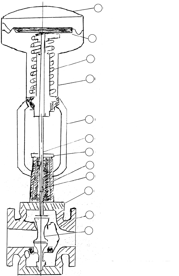
Figure 13.2 shows a conventional control valve which in this case is taken as a double
seated plug type valve. Like most control valves it is operated pneumatically by an
air stream exerting a pressure on a diaphragm which in turn allows the movement of
a spring loaded valve stem. One or two plugs (the diagram shows two) are attached to
the bottom of the valve stem which, when closed, fit into valve seats thus providing
SUPPORT SYSTEMS COMMON TO MOST REFINERIES 529
1 INNER VALVE
2 BODY
3 BONNET
4 PACKING
5 STUFFING BOX
6 GLAND
7 VALVE STEM
8 YOKE
9 SPRING BARREL
1 INNER VALVE
10 SPRINGS
11 DIAPHRAM AND PLATE
12 DIAPHRAM DOME
12
11
10
9
8
7
6
5
4
3
2
1
Figure 13.2. A conventional control valve.
530 CHAPTER 13
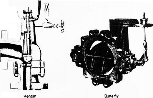
Figure 13.3. The venturi and butterfly control valves.
tight shut off. The progressive opening and closing of the plugs on the valve seats
due to the movement of the stem, determines the amount of the controlled fluid
flowing across the valve. The pressure of the air to the diaphragm controlling the
stem movement is varied by a control parameter, such as a temperature measurement,
or flow measurement, or the like. In many of the more modern refineries many control
valves are operated electronically.
Figure 13.3 shows two other types of control valves in common service in the industry.
These are the venturi type and the butterfly type. Both these types when pneumatically
operated (which they usually are) work in the same way as described above for a plug
type valve. The major difference in these two types are in the valve system itself. In
the case of the venturi the fluid being controlled is subjected to a 90
◦
angle change
in direction within the valve body. The inlet and outlet dimensions are also different,
with the inlet having the larger diameter. The valve itself is plug type but seats in the
bend of the valve body. Venturi type or angle valves are used in cases where there
exists a high-pressure differential between the fluid at the inlet side of the valve and
that required at the outlet side.
Butterfly valves operate at very low-pressure drop across them. They can operate quite
effectively at only inches of water gauge pressure drop, and where the operation of the
conventional plug type valves would be unstable. The action of this valve is by means
of a flap in the process line. The movement of this flap from open to shut is made by
a valve stem outside the body itself. This stem movement, as in the case of the other
pneumatically operated valves, is provided by air and spring loads onto the stem from
a diaphragm chamber. The only major disadvantage in this type of valve is the fact
that very tight shut off is difficult to obtain due to the flap type action of the valve.
SUPPORT SYSTEMS COMMON TO MOST REFINERIES 531
The plug valve
There are two types of plug valves used for the conventional control valve function.
These are:
r
Single seated valves
r
Double seated valves
Single seated valves are inherently unbalanced so that the pressure drop across the
plug affects the force required to operate the valve. Double seated valves are inherently
balanced valves and are the first choice in most services.
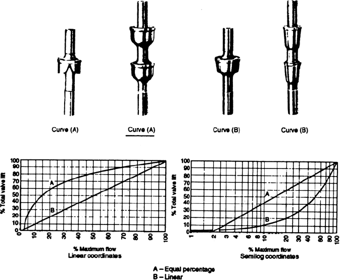
The conventional control valves predominantly in use can have either an equal percent-
age, or linear characteristics. The difference between these two is given in Figure 13.4.
With an equal percentage characteristic, equal incremental changes in valve stem lift
result in equal percentage changes in the flow rate. For example if the lift were to
Figure 13.4. Control valve characteristics.
532 CHAPTER 13
change from 20% to 30% of maximum lift the flow at 30% would be about 50% more
than the flow at 20%. Likewise, if the lift increases from 40% to 50% the flow at 50%
would be about 50% more than at 40%.
With a linear valve having a constant pressure drop across it, equal incremental
changes in stem lift results in equal incremental changes in flow rate. For example,
if the lift increases from 40% to 50% of maximum, the flow rate changes from 40%
to 50% of maximum. Thus equal percentage is the more desirable characteristic for
most applications and is the one most widely used.
Pressure drop across control valves
In sizing or specifying the duty of the control valve the pressure drop across the
control valve must be determined for the design or maximum flow rate. In addition,
if it is known that a valve must operate at a flow rate considerably lower than the
maximum rate, the pressure drop at this lower flow rate must also be calculated. This
will be required to establish the range ability of the valve.
As a general rule of thumb the sum of following pressure drops at maximum flow
may be used for this purpose:
(a) 20% of the friction drop in the circuit
1
(excluding the valve).
(b) 10% of the static pressure of the vessel into which the circuit discharges up to
pressures of 200 psig, 20 psig from 200 to 400 psig, and 5% above 400 psig.
The static pressure is included to allow for possible changes in the pressure level in
the system (i.e., by changing the set point on the pressure controller on a vessel). The
percentage included for static pressure can be omitted in circuits such as recycle and
reflux circuits in which any change in pressure level in the receiver will be reflected
through the entire circuit. In some circuits the control valve will have to take a much
greater pressure drop than calculated from the percentages listed above. This occurs
in circuits where the control valve serves to bleed down fluid from a high-pressure
source to a low-pressure source. Examples are pressure control valves releasing gas
from a tower or streams going out to tankage from vessels operating at high pressure.
These are the circumstances where venturi or angle valves are used, as described
earlier.
Valve action on air failure
In the analysis of the design and operation of any process or utility system the question
always arises on the action of control valves in the system on instrument air failure.
1
A circuit generally includes all equipment between the discharge of a pump, compressor or vessel and
the next point downstream of which pressure is controlled. In most cases this latter point is a vessel.
