Jones D.S.J., Pujado P.R. Handbook of Petroleum Processing
Подождите немного. Документ загружается.

1006 CHAPTER 18
Condensers. Condensing vapors should flow on the shell side wherever possible. The
larger free area provided by the shell side space permits minimum pressure drop and
higher condensate loading through better film heat transfer coefficients.
Large flow rates. In cases where both streams are of a similar nature with similar
properties the stream with the largest flow rate should be sent to the shell side where
the difference in flow rates are significant. The shell side provides more flexibility in
design by baffle arrangements to give the best heat transfer design criteria.
Boiling service. The boiling liquid as in the case of reboilers, waste heat recovery
units and the like should be on the shell side of the exchanger. This allows space for
the proper disengaging of the vapor phase and provides a means of controlling the
system by level control of the liquid phase.
Types of shell and tube exchangers
Figure 18.33 gives some of the more common arrangements in shell and tube ex-
changer design. The arrangements shown here are all one shell pass and one or two
tube passes. Equipment with more than two tube passes (up to five) is also fairly
common particularly in petroleum refining. Shell arrangements are however left at
one if at all possible. Where multi-pass shell side is required companies prefer to use
complete exchangers in series or in parallel or both rather than making two or more
shell passes using horizontal baffling in one exchanger.
Estimating shell and tube surface area and pressure drop
There are many excellent computer programs available that calculate exchanger sur-
face area and pressure drops from simple input. The actual calculation when done
manually is tedious and long. However to understand a little of the importance of
the input required by these computer programs it does well to at least view a typical
manual calculation. The one given here is for a shell and tube cooler with no change
of phase for either tube side or shell side fluids.
The calculation follows these steps:
Step 1. Establish the following data by heat balances or from observed plant readings:
r
The inlet and outlet temperatures on the shell side and on the tube side.
r
The flow of tube side fluid and that for the shell side. It may be necessary to
calculate one or the other from a heat balance over the exchanger.
r
Calculate the duty of the exchanger in heat units per unit time (usually hours).
r
Establish the stream properties for tube side and shell side fluids. The properties
required are: SG, Viscosity, Specific heats, Thermal conductivity.
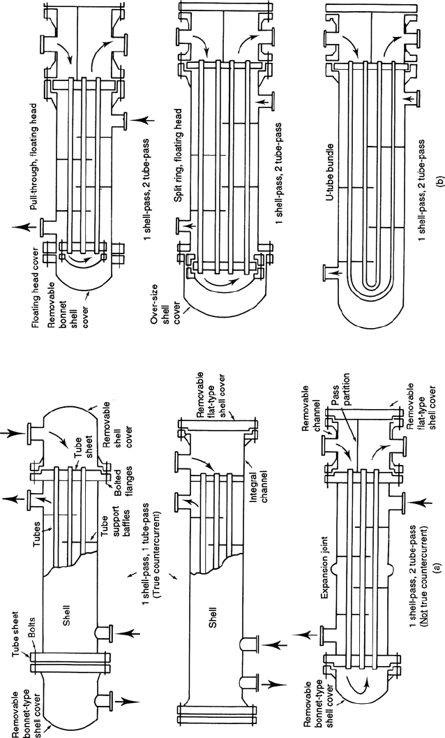
Figure 18.33. Some Common types of shell and tube exchangers. (a) Fixed tube sheet. (b) Removable bundle.

1008 CHAPTER 18
Step 2. Calculate the log mean temperature difference (t
m
).
Assume a flow pattern (i.e. either co current or counter-current). Most flows will
be a form of counter-current. Then show the temperature flow as follows:
Shell In −−−−−−−−−−→
䉴
Shell Out
Tube out
䉳
←−−−−−−−−−− Tube In
Temp difference t
1
t
2
The log mean temperature difference is then calculated using the expression:
t
m
=
t
1
− t
2
log
e
t
1
t
2
This temperature needs to be corrected for the flow pattern, and this is done using
the correction factors given in Figure 18.A.1. The use of these are self explanatory
and are given in the figure.
Step 3. Calculate the approximate surface area.
From Table 18.A.2 in the Appendix select a suitable overall heat transfer coefficient
U in Btu’s/hr. sqft. F. Use the expression to calculate for ‘A’:
Q = UAt
m
where
Q = Heat transferred in Btu/hr. (the exchanger duty)
U =Overall heat transfer coefficient.
A = Exchanger surface area in sqft.
t
m
=Log mean Temperature difference (corrected for flow pattern) in
◦
F.
From the surface area calculated select the tube size and pitch. Usually
3
/
4
ins on
a triangular pitch for clean service and 1
on a square pitch for dirty or fouling
service. A single standard shell will hold about 4,100 sqft of surface per pass. Now
most companies do not use multi-pass shells and prefer sets of shells in series if this
becomes necessary. The ‘norm’therefore are single pass shells each containing up
to 4,100 sqft of surface.
Step 4. Calculate the tube side flow and the number of passes.
If it cannot be read from plant data calculate tube side flow in cuft/hr by heat balance.
Select the tube gauge and length. The tube data are given in Table 18.A.3 in the
Appendix and standard lengths of tubes are 16 and 20 ft. Calculate the number of
selected tubes per pass from the expression:
Np =
Ft × 144
3,600 × At × Vt

PROCESS EQUIPMENT IN PETROLEUM REFINING 1009
where
Np = number of tubes per pass
Ft = tube side flow in cuft/hr
At = cross-sectional area of 1 tube
Vt = linear velocity in tube in ft/sec
See earlier item on ‘Fluid Velocities and Pressure Drop’for recommended fluid ve-
locities. The number of tube passes is arrived at by dividing the total surface area re-
quired by the total (external) surface area of the number of tubes per pass calculated
above.
Step 5. Calculate tube side film coefficient corrected to outside diameter (h
io
).
The tube side film coefficient may be calculated for water by the expression:
h
io
=
300 × (V
t
× tube i/d ins)
0.8
tube o/d ins
where
h
io
=Inside film coefficient based on outside tube diameter in Btu/hr sqft
◦
F.
V
t
=linear velocity of water tube side in ft/sec.
For fluids other than water flowing tube side use the expression:
h
io
=
K
D
o
(Cµ/K )
1/6
(µ/µ
w
) · φ(DG
.14
/µ)
where
h
io
=inside film coefficient based on outside diameter in Btu/hr sqft
◦
F.
K = thermal conductivity of the fluid in Btu/hr sqft (
◦
F per ft). See
Maxwell Data Book on Hydrocarbons or Perry Chemical Engineers
Handbook
D =Inside tube diameter in ins.
D
o
=Outside tube diameter in ins.
C =Specific heat in Btu/lb/
◦
F.
G = mass velocity in lbs/sec sqft.
µ =Absolute viscosity Cps at average fluid temp.
µ
w
=Absolute viscosity Cps at average tube wall temp.
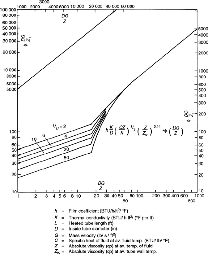
φ(DG/µ) =from Figure 18.34.
Step 6. Calculate shell side dimensions.
First determine the shell side average film temperature as follows:
Inlet ave =
T
1
+ T
2
2
Outlet ave =
T
3
+ T
4
2
1010 CHAPTER 18
Figure 18.34. Heat transfer inside tubes.
where
T
1
=Shell fluid inlet temperature.
T
2
=Tube outlet temperature.
T
3
=Shell outlet temperature.
T
4
=Tube inlet temperature.

PROCESS EQUIPMENT IN PETROLEUM REFINING 1011
Average shell side film temperature:
Inlet ave + outlet ave
2
Use this temperature to determine density and viscosity used in the shell side film
coefficient calculations.
The shell diameter. Next calculate the diameter of the tube bundle and the shell
diameter. For this use one of the following equations to calculate the number of tubes
across the center line of the bundle:
1. For square pitch tube arrangement:
T
cl
= 1.19 (number of tubes)
0.5
2. For triangular pitch tube arrangement:
T
cl
= 1.10 (number of tubes)
0.5
Note these are total number of tubes; namely, those calculated in Step 4 times number
of tube passes.
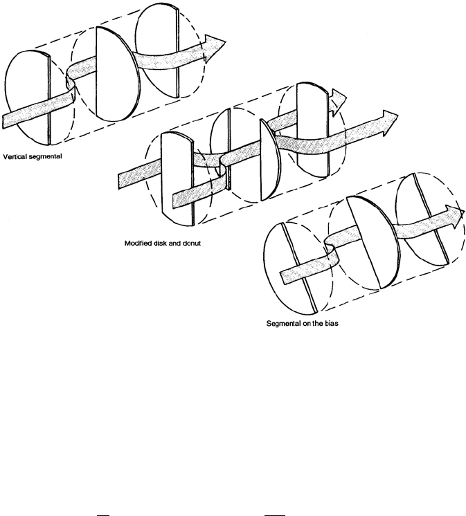
Set number of baffles and their pitch. The type of baffles usually used are shown in
Figure 18.35. Disc and donut type baffles are only used where pressure drop available
is very small and there is a pressure drop problem. Baffles on the bias are used in sq
pitch tube arrangement and baffles perpendicular to the tubes are usual for triangular
tube arrangements.
The minimum baffle pitch should not be less than 16% of the shell diameter. Pitch in
this case is the space between two adjacent baffles. Normally 20% of shell i/d is used
for the baffle pitch. The number of baffles is calculated from the expression:
N
B
=
10 × tube length
baffle pitch % × diameter of shell.
Free area of flow between baffles. The space available for flow on the shell side is
calculated as:
W = D
i
− (d
o
× T
cl
)
where
W = space available for flow in sq ins.
D
i
=shell inside diameter in ins.
d
o
=tube outside diameter in ins.
T
cl
=number of tubes across centerline.
The free area of flow between baffles is now calculated as follows:
A
f
= W ×(B
p
− 0.187)
1012 CHAPTER 18
Figure 18.35. Types of baffles.
where
A
f
=free flow area between baffles in sq ins.
B
p
=baffle pitch in ins.
Step 7. Calculate the shell side film coefficient h
o
.
The following expression is used to determine the outside film coefficient:
h
o
=
K
d
o
(Cµ/K )
1/3
· φ(d
o
G
m
/µ
f
) ·
4P
b
D
where
h
o
=outside film coefficient in Btu/hr sqft
◦
F
G
m
=maximum mass velocity in lbs/sec. sqft
d
o
=outside tube diameter in ins
K = thermal conductivity.
C =specific heat of fluid in Btu/lb/F
µ
f
=viscosity at mean film temperature in Cps
P
b
=baffle pitch in ins
D =shell internal diameter in ins
PROCESS EQUIPMENT IN PETROLEUM REFINING 1013
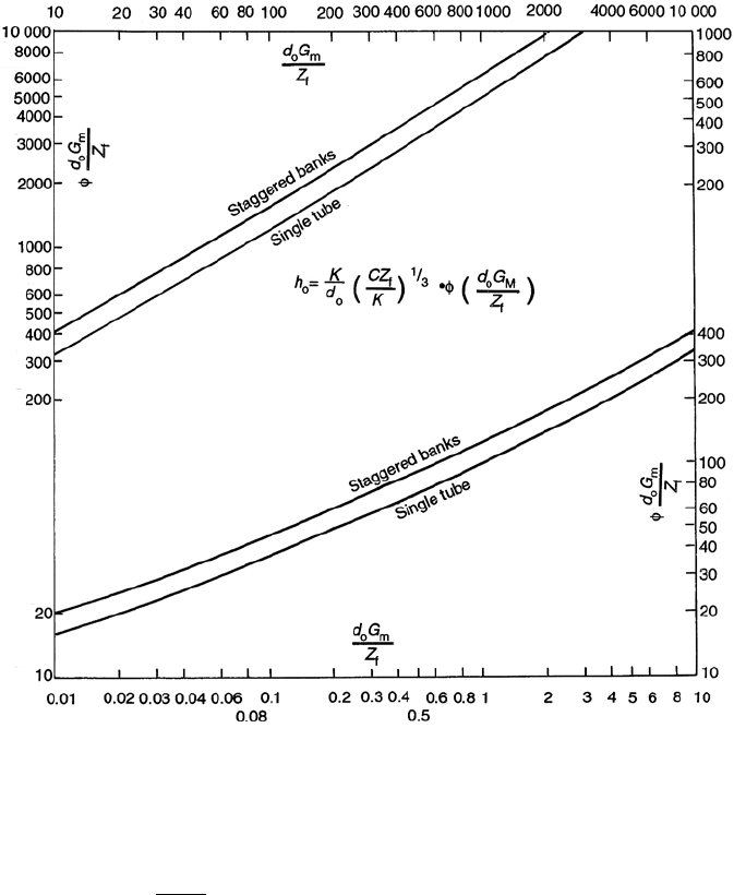
Figure 18.36. Heat transfer to fluids outside tubes.
φ(d
o
G
m
/µ
f
) is a function of the Reynolds number read from Figure 18.36. The
Reynolds Number is:
Re =
d
o
G
m
µ
f
where G
m
= lbs/sec sqft.
This film coefficient is corrected for the type of baffle and tube arrangement by
multiplying it by one of the following factors:
For square pitch vertical to tube rows 0.50
square pitch on the bias 0.55
triangular tube pitch 0.70

1014 CHAPTER 18
Table 18.28. Thermal conductivity of tube
metals
K , Btu/hr.sqft. F/ft
Admiralty brass 64
Aluminum brass 58
Aluminum 117
Brass 57
Carbon steel 26
Copper 223
Cupronickel 41
Lead 20
Monel 15
Nickel 36
Red Brass 92
Type 316 alloy steel 9
Type 304 alloy steel 9
Zinc 65
Step 8. Calculate the overall heat transfer coefficient U
o
.
The film coefficients calculated in steps 5 and 7 are now used in the expression:
1
U
o
=
1
h
io
+r
io
+
1
h
o
+r
o
+r
w
where
U
o
= overall heat transfer coefficient in Btu/hr.sqft.
◦
F.
r
io
and r
o
= tube side and shell side fouling factors respectively in hr. sqft.
◦
F/Btu.
For clean tubes this is 0.001 as a sum of both factors.
r
w
= Tube wall resistance to heat transfer in hr. sqft.
◦
F/Btu, which is expressed as:
r
w
=
t
w
· d
o
12 × K × (d
o
− 2t
w
)
where
t
w
=Tube wall thickness ins.
d
o
=Outside tube diameter ins.
K = Thermal conductivity Btu’s/hr sqft
◦
F/ft. See Table 18.28.
Compare the calculated value of the overall heat transfer coefficient with the as-
sumed one in step 3.
If there is agreement within ±10% then the calculated one will be used for revising
the calculation for surface area and the other dimensions. If there is no agreement
repeat the calculation using a new value for the assumed U .
PROCESS EQUIPMENT IN PETROLEUM REFINING 1015
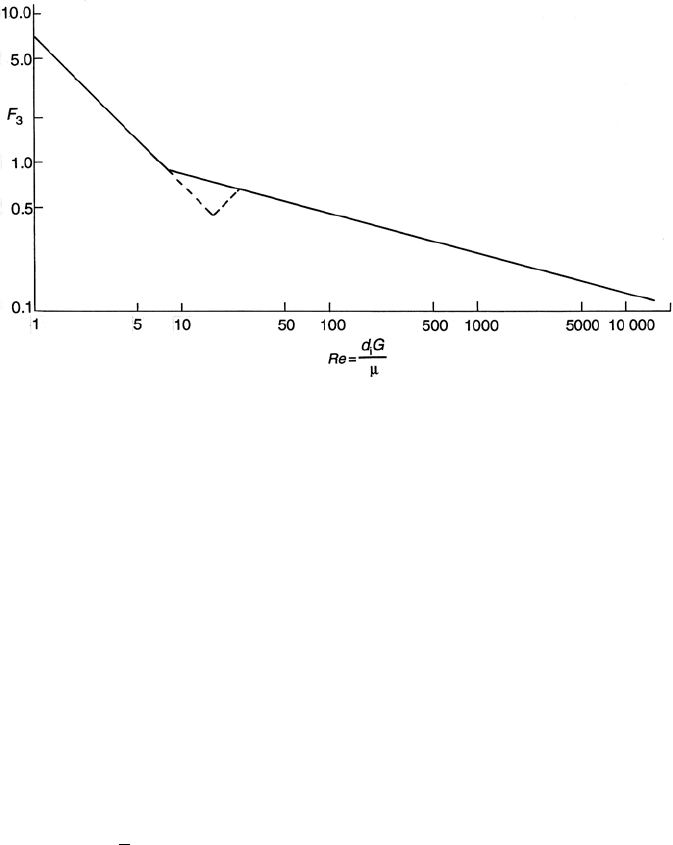
Figure 18.37. Pressure drop factor F
3
for flows inside tubes.
Step 9. Calculate tube side pressure drop.
Using the adjusted dimensional values from the calculated U
o
, calculate the tube
side pressure drop using one of the following equations:
P
t
= .02F
t
× N
p
× (V
2
+ (0.158LV
1.73
/d
i
)
1.27
)
For water only.
For fluids other than water use:
P
t
= F
t
× N
p
× (P
tf
+ P
tr
)
where
P
tf
= F
3
·
L
d
i
· (ρ
m
× V
2
/9, 270) · (µ
w
)
.14
P
tr
=3 ×(ρ
m
× V
2
/9, 270)
F
3
=factor based on Reynolds number see Figure 18.37
ρ
m
=density in lbs/cuft at mean fluid temperature.
µ
w
=viscosity of fluid at tube wall temperature in Cps (use mean film
temperature)
V = linear velocity in ft/sec.
F
t
=pressure drop fouling factor as follows (dimensionless)
