Jones D.S.J., Pujado P.R. Handbook of Petroleum Processing
Подождите немного. Документ загружается.

1026 CHAPTER 18
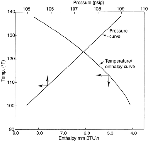
Figure 18.43. Enthalpy curve for a de-butanizer overhead condenser.
N
s
=2.08 N
0.495
t
for triangular pitch.
k
f
=thermal conductivity of condensate at film temperature.
Sg =specific gravity of condensate.
µ
f
=viscosity of condensate at film temperature in Cps
Again there are many excellent computer programs that calculate condenser thermal
ratings, and these of course save the tedium of the manual calculation. However no
matter which method of calculation is selected there is required one major additional
piece of data over that required for single phase heat exchange. That item is the
enthalpy curve for the vapor.
Enthalpy curves are given as the heat content per lb or per hour contained in the mixed
phase condensing fluid plotted against temperature. An example of such a curve is
given in Figure 18.43. These Enthalpy curves are developed from the vapor/liquid or
flash calculations described in Chapter 3 of this volume.
Briefly the calculation for the curve commences with determining the dew point of
the vapor and the bubble point of the condensate. Three or more temperatures are
PROCESS EQUIPMENT IN PETROLEUM REFINING 1027
selected between the dew and bubble points and the V /L calculation of the fluid at
these temperatures carried out. Enthalpy for the vapor phase and the liquid phase are
added for each composition of the phases at the selected temperatures. These together
with the enthalpy at dew point and bubble point are then plotted.
As in the case of the shell and tube exchanger and the air cooler a manual calculation
for condensers is described here. Again this is done to provide some understanding of
the data required to size such a unit and its significance in the calculation procedure.
Computer aided designs should however be used for these calculations whenever
possible.
The following calculation steps describe a method for calculating the film coefficient
of a vapor condensing on the shell side of a S&T exchanger. The complete rating
calculation will not be given here as much of the remaining calculation is simply
repetitive.
Step 1. Calculate the dew point of the vapor stream at its source pressure. Estimate
the pressure drop across the system. Usually 3–5 psi will account for piping and
the exchanger pressure drop. Calculate the bubble point of the condensate at the
terminal pressure. Select three or more temperatures between dew point and bubble
point and calculate the vapor/liquid quantities at these conditions of temperature
and pressure.
Step 2. Calculate the enthalpy of the vapor and liquid at these temperatures. Plot the
total enthalpies against temperature to construct the enthalpy curve. Establish the
properties of the vapor phase and liquid phase for each temperature interval.
The properties mostly required are Sg, viscosity, Mole wt, thermal conductivity,
and specific heats.
Step 3. In the case of a water cooler calculate the duty of the exchanger and the
quantity of water in lbs/hr. Commence the heat transfer calculation by assuming
an overall heat transfer coefficient (use the data given in Table A9.1). Calculating
the corrected LMTD, and the surface area.
Step 4. Using the surface area calculated in step 3 define the exchanger geometry in
terms of number of tube passes, number of tubes on the center line, shell diameter,
baffle arrangement and the shell free flow area. Calculate also the water flow in
feet per sec.
Step 5. Divide the exchanger into 3 or 4 zones by selecting the zone temperatures on
the enthalpy curve. Calculate the average weight of vapor and the average weight of
condensate in each zone. Using these averages calculate the average heat transferred
for:
Cooling of the vapor Q
v
Cooling of the condensate Q
L
Condensing of the vapor which will be:
Total heat in the zone (from the enthalpy curve) less the sum of Q
v
and Q
L
.

1028 CHAPTER 18
Step 6. Calculate the film coefficient for the tube side fluid. See previous item ‘Esti-
mating Shell and Tube Surface Area and Pressure Drop’.
Step 7. Starting with zone 1 and knowing the outlet temperature of the coolant fluid,
the total heat duty of the zone, and the shell side temperatures calculate the coolant
inlet temperature. Using this calculate the LMTD for the zone and, assuming a zone
overall heat transfer coefficient U, calculate a surface area for the zone. Using this
and the total exchanger area estimated in step 4 establish L
c
in feet.
Step 8. Calculate the condensing film coefficient from the equation given earlier. This
will be an uncorrected value for h
c
. This will be corrected to account for turbulence
by the expression:
h
c (corr)
= h
c
× (G
v
/5)
where
G
v
= average vapor mass velocity in lbs/hr · sqft
Step 9. Calculate the value of G
v
using the free flow area allocated to the vapor γ
v
.
The following expressions are used for this:
γ
v
= 1 − γ
L
1
γ
L
= 1 +
Ave mass vapor
Ave mass liquid
× (µ
v
/µ
L
)
0.111
× (ρ
L
/ρ
v
)
0.555
G
v
=
Ave mass Vapor
25 × Free flow area ×γ
v
Step 10. Calculate the film coefficient hv for the vapor cooling mechanism. This
will be the procedure used for a single phase cooling given in a previous item.
This is corrected to account for resistance of the condensate film by the expres-
sion:
1
h
v corr
=−
1
h
c
+
1
1.25h
v
Step 11. Calculate the film coefficient for the condensate cooling mechanism. Again
this is the procedure described in the Item for single phase cooling on the shell
side. This is corrected for drip cooling that occurs over a tube bank.
Drip cooling h
dc
= 1.5 × h
c
and h
L
corrected =
2 × h
dc
× h
L
h
dc
+ h
L

PROCESS EQUIPMENT IN PETROLEUM REFINING 1029
Step 12. Calculate the total zone film coefficient ho using the following expression:
h
o
=−
Q
zone
Q
c
h
c
+
Q
v
h
v
+
Q
L
h
L
where
Q
c
, Q
v
, Q
L
are the enthalpies for condensing, vapor cooling, and condensate cool-
ing, respectively.
Step 13. Calculate the overall heat transfer coefficient neglecting the shell side coef-
ficient from Step 12. Thus:
1
U
x
= r
o
+r
w
+r
io
+ R
io
where
r
o
, r
w
, r
io
are fouling factors for shell fluid, wall, and tube side fluid respectively.
R
io
is the tube side film coefficient calculated in Step 6.
Step 14. Calculate the overall heat transfer coefficient U
zone
for the zone using the
expression:
U
zone
=
h
o
× U
x
h
o
+ U
x
Check the calculated U against that assumed for the zone. Repeat the calculation
if necessary to make a match.
Step 15. Calculate the zone area using the acceptable calculated U . Repeat steps 7
through 14 for the other zones. The total surface area is the sum of those for each
zone.
Reboilers
Reboilers are used in fractionation to provide a heat source to the system, and to
generate a stripping vapor stream to the tower. Reboilers are operated either by the
natural circulation of a fluid or by forced circulation of the fluid to be reboiled. This
chapter deals only with natural circulation reboilers.
There are three common types of reboilers and these are:
r
The kettle type reboiler
r
The once through thermosyphon reboiler
r
The re-circulating thermosyphon reboiler
1030 CHAPTER 18
The kettle reboiler
This type of reboiler (Figure 18.44) is extremely versatile. It can handle a very wide
range of vaporization loads. (e.g., when used as LPG vaporizer for fuel gas purposes
it vaporizes 100% of the feed). The equipment consists of a large shell into which
is fitted a tube bundle through which the heating medium flows. The liquid to be
reboiled enters the bottom of the shell at the end adjacent to the tube inlet/outlet
chamber. The liquid is boiled and partially vaporized by flowing across the tube
bundle. The diameter of the shell is sized such that there is sufficient space above
the tube bundle and the top of the shell to allow some disengaging of the liquid and
vapor. A baffle weir is installed at the end of the tube bundle furthest from the inlet.
This baffle weir establishes a liquid level over the tube bundle in the shell. The boiling
liquid flows over this weir to the shell outlet nozzle, while the vapor generated is
allowed to exit from the top of the shell through one or two nozzles.
The space downstream of the weir is sized for liquid holdup to satisfy the surge
requirements for the product. Thus it is not necessary to provide space in the bottom
of the tower for product surge. If the heating medium is non fouling it is permissible
to use U tubes for the tube bundle. Otherwise the tube bundle must be of the floating
head type. The kettle type reboiler should always be the first type to be considered if
there are no elevation constraints to pumping the bottoms product away.
Once through thermosyphon reboiler
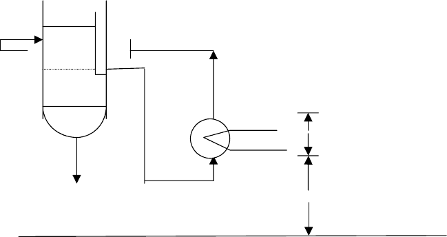
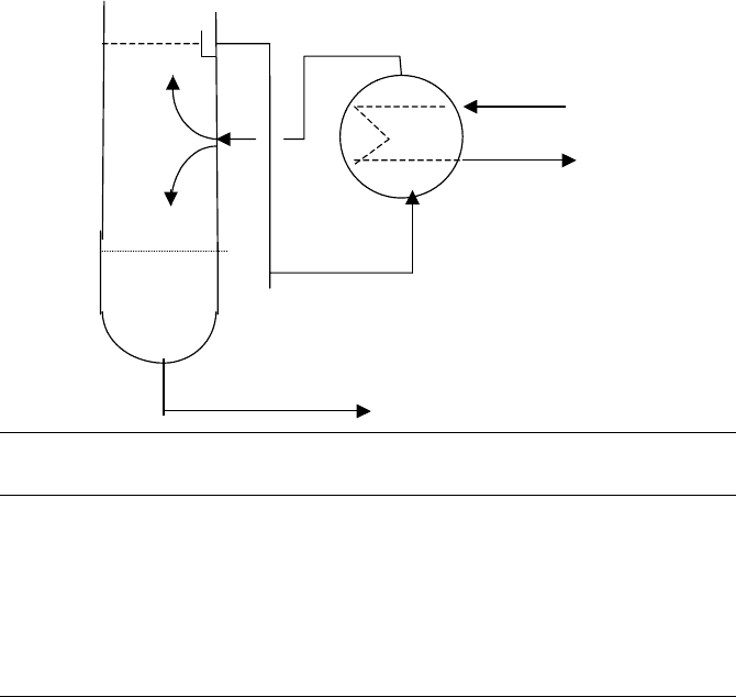
This type of reboiler and its location relative to the tower is given in the sketch below:
As required for circulation
Product
3.0 ft min.
Grade
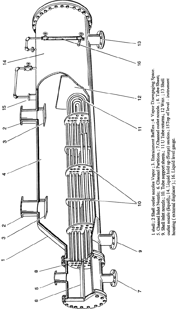
Figure 18.44. The components of a kettle reboiler.
1032 CHAPTER 18
This type of reboiler should be considered when a relatively high amount of surge
is required for the bottom product and when it is necessary to provide head for the
product pump (NPSH requirement).
This type of reboiler takes the liquid from the bottom tray of the fractionator as feed.
This stream enters the shell side of a vertical single tube pass shell and tube exchanger
by gravity head to the bottom of the shell. The heating medium flows tube side to
partially vaporize the liquid feed. A siphoning effect is caused by the difference in
density between the reboiler feed and the vapor/liquid effluent. This allows the reboiler
effluent to exit from the top of the shell side and reenter the tower where the vapor
disengages from the liquid phase. The liquid is the bottom product of the fractionator
and is discharged from the bottom of the tower.
Both the kettle type and the once through thermo-siphon type constitute a theoretical
tray as regards fractionation. Unlike the kettle reboiler the once through thermo-siphon
is limited to a vaporization of not more than 60% of the feed. The low holdup of the
feed from a tray results in severe surging through the reboiler at high vaporization
rates.
The re-circulating thermo-siphon reboiler
When vaporization rates higher than 60% of reboiler feed is required and a kettle re-
boiler is unsuitable a recirculating Thermo-siphon type reboiler should be considered.
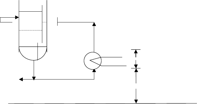
A sketch showing this type of reboiler is given below:
As required for circulation
Product
3.0 ft min.
Grade
This reboiler is similar to the once through thermo-siphon in as far as it operates
by flowing a liquid feed through the shell side of the vertical reboiler by the siphon
PROCESS EQUIPMENT IN PETROLEUM REFINING 1033
mechanism. In the case of the recirculating reboiler however the feed to the reboiler
is a stream of the bottom product from the fractionator. This is vaporized as described
earlier and the liquid/vapor effluent returned to the tower. The vaporization by this
reboiler can exceed 60% without danger of surging. However vaporization in this type
of reboiler should not exceed 80%. Its action is directed solely to imputing heat to
the tower and, because it recycles the same composition stream to the tower bottom,
it cannot be considered as a theoretical fractionating tray. (Although some amount of
fractionation does occur in this system).
Note in the description of both the thermo-siphon type reboilers the heating fluid is
shown as flowing tube side. There may be cases where this stream will be routed
shell side and the reboil fluid directed tube side. Some guidance to this selection is
provided by the following preference for tube side fluid:
1. Corrosive or fouling fluids.
2. The less viscous of the two fluids.
3. The fluid under the higher pressure.
4. Condensing steam.
Reboiler sizing
As in the case of most heat exchangers the sizing calculation is quite rigorous and
complex. Normally process engineers rarely need to compute this in detail. There
will be need however to estimate the size of these items for cost purposes or for plot
layout studies. This sizing is greatly simplified by applying heat flux quantities to the
predetermined reboiler duty. Heat flux is the value of heat transferred per unit time
per sqft of surface. The following list gives a range of heat fluxes that have been used
in design and observed in operating units.
Design Observed
(Btu/hr · sqft)
Kettle type 12,000 15,000–20,000
Once through 15,000 17,500+
Recirculating 15,000 up to 20,000
Forced circulation 20,000 –
The duty of the reboiler is obtained by the overall heat balance over the tower. This
is accomplished by equating the total heat out of a fractionating tower to the heat
supplied, making the reboiler duty the unknown in the heat supplied statement. Now
the heat out of the fractionator is the total heat in the products leaving plus the
condenser duty. The heat supplied to the tower is the heat brought in with the feed,
and the heat supplied by the reboiler.

1034 CHAPTER 18
Example calculation
The feed to a fractionator is 87,960 lbs/hr of mixed hydrocarbons. It enters the tower as
a vapor and liquid stream and has a total enthalpy of 15.134 mm Btu/hr. The overhead
products are a distillate and a vapor stream at 95
◦
F. The vapor is 1,590 lb/hr with an
enthalpy of 320 Btu/lb. The distillate is 8,028 lbs/hr with an enthalpy of 170 Btu/hr.
The bottom product from the tower is 78,342 lbs/hr and leaves as a liquid at its boiling
point at 440
◦
F. Its enthalpy is 370 Btu/lb. The overhead condenser duty is 4.278 mm
Btu/lb. Calculate the reboiler duty.
Calculation
Calculate the reboiler duty from the overall tower heat balance as in the following:
Enthalpy,
V/L
◦
API
◦
F lbs/hr Btu/lb mm Btu/hr
In
Feed VL – 300 87,960 – 15.134
Reboiler duty x
Total In 87,960 15.134 + x
Out
Bottom Prod L – 440 78,342 370 28.986
O/head Dist L – 95 8,028 170 1.364
O/head vapor V – 95 1,590 320 0.508
Condenser duty 4.278
Total out 87,960 35.136
Heat In = Heat Out
Then
15.134 + x = 35.136
Reboiler duty x = 20.002 mm Btu/hr.
Using a heat flux of 15,000 Btu/hr sqft the surface area for the reboiler becomes
20002000
15,000
= 1,333.5 sqft.
Estimating the liquid and vapor flow from the reboiler
It is necessary to know the vapor and liquid flow leaving the reboiler and entering the
tower for the following reasons:
r
To establish that there is sufficient vapor rising in the tower to strip the bottom
product effectively
r
To establish the vapor loading to the bottom tray for calculating the tray loading
PROCESS EQUIPMENT IN PETROLEUM REFINING 1035
r
To be able to calculate the driving force for flow through the exchanger in the case
of thermo-siphon reboilers
The calculation of this flow is again based on a heat balance. In this case it is the heat
balance across the reboiler itself. With the duty of the reboiler now established by
the overall tower heat balance, as described above, the balance over the reboiler can
proceed as follows:
V
Steam
Condensate
L
227 psia
440 F
Product
Enthalpy,
V/L
◦
API
◦
F lbs/hr Btu/lb mm Btu/hr
In
Liquid from tray 1 L – 430 78,342 + V 369 28.908 + 369 V
Reboiler duty 20.002
Total In 7,834 + V 48.910 + 369 V
Out
Bottom prod L – 440 78,342 370 + 28.986
Vapor to tray 1 V – 440 V 458 + 458 V
Total Out 78,342 + V 28.986 + 458 V
The temperature of the bottom tray (430
◦
F) is estimated from a straight line temper-
ature profile of the tower. As a rule of thumb—for a 30 to 40 tray tower the bottom
tray will be about 10
◦
F lower than the bottom temperature.
Again Heat In = Heat Out
Then 48.910 + 369 V = 28.986 + 458 V
V = 223,865 lbs/hr
