Jackson Mark. Machining with Abrasives
Подождите немного. Документ загружается.


importance, but its shape and surface structure were for the tool-workpiece inter-
actions. Its surfaces were formed by preferred diamond/fcc cleavage planes and
were used as rake and clearance faces. The edge radius was not chosen to be
atomically sharp (2 nm) in order to consider limited mi nimum edge radii because
of surface stresses. To further provide a reasonable tool-workpie ce contact model,
the tool structure had the atomic density of diamond. Although the tool was
modeled as a hard body with collectively moving atoms, i.e., no interaction within
the tool, the interaction potential between tool and workpiece atoms needed to be
specified. Data for the diamond/copper interactions based on a pair potential
function were found. The cutting forces were calculated as reaction forces at the
tool due to its feed motion. The work atom interactions are described by the EAM
potential for copper. Th e cutting speed was restricted to 100 and 50 m/s. Lower
speeds were not practical to simulate due to computational limitations.
Figure 7.1 shows a single-crystalline structure, that moved relative towards the
cutting tool, whereupon material is deformed in front of the tool tip, the chip
generation is initiated and dislocation loops can be identified at the generated
workpiece surface. It shows areas of plastic deformation, dislocations and large
elastic deformations in the sub-surface region. The method is based on horizontal
and vertical connections between initial-neighbor atoms. Deformations show as
sharp equilateral folds in neighboring layer lines within the otherwise rectangular
structure or by narrowing mesh spacing as in case of strong elastic deformation. For
large displacements between initial-neighbor atoms, the bond was considered to be
broken and was not drawn anymore. In this way, highly deformed areas, like the
chip and the newly generated surface, show few initial-neighbor lines. Deep
running dislocations, observed in 2D MD cutting simulations if pair potentials are
being used, could not be confirmed by employing this 3D model and the better
EAM potential. This model predicts intensive plastic deformation at the generated
surface with a thickness of only a few atom layers. At the same strain, a 2D model
Fig. 7.1 Deformation graph, view <110> (after Rentsch in Davim and Jackson [1]). Used with
permission copyright ISTE-Wiley (2009)
7 Nanogrinding 305
always predicts larger dislocations than its 3D counterpart. The cutting process
changes drastically when changing the ratio of depth of cut to cutting edge radius
from 0.5 to 1.0, depending also on the crystalline orientation of the work. At a ratio
of a/r ¼1.0, the tool begins to utilize more its rake face for the chip formation. With
the increase in depth of cut, the portion of twin dislocations in chip formation
increases over dislocation slipping.
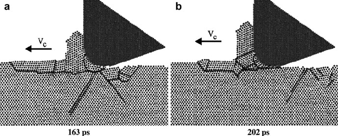
Such twinned areas can be seen ahead of the tool and the chip. The lower energy
requirement for twinning makes the chip removal process at larger depth of cut
more efficient and the cutting forces only increase under proportionally. Figure 7.2
shows two subsequent 2D views of microstructural snapshots of the same model as
in Fig. 7.1, but at smaller depths of cut than before. Analyzing the changes in the
microstructure deepens the understanding of the mechanisms of material removal
for specific cutting conditions. In Fig. 7.2 areas with different crystal orientation are
separated by lines and slip lines drawn for identified dislocations. Until state (a) was
reached, the pre-deformation area in cutting direction (ahead of the chip) increased
without an increase in chip length. Until state (b) was reached, this process had
stopped, the pre-deformation area decreased while the chip grew in size. The micro
structural plots show a change of the crystal orientation in the chip root area, that
supports either the deformation away from the chip root (a) or the chip formation in
the chip root area.
7.3 Cutting Forces, Stress and Temperature
By modeling systems of discrete particles and observing their progression over
time, statistical mechanics provides a basis for the analysis and the description of
the behavior of such systems. It has been demonstrated for a Gibbs micro canonical
Fig. 7.2 Micro structural changes in the chip root area during chip formation (after Rentsch in
Davim and Jackson [1]). Used with permission copyright ISTE-Wiley (2009)
306 M.J. Jackson and J. P. Davim
ensemble, that taking time averages is in statistical agreement with taking phase-
space averages and, that the numerical quality of results in MD can always be
improved by longer calculations.
Cutting forces can be calculated as reaction forces at the tool due to its relative
motion during contact with the workpiece atoms. For every time step Dt, which is
usually in the range of a few femtoseconds (10
15
s), the force contributions of the
workpiece atoms interacting with the tool are integrated. The dynamic character of
such a system with a large number of degrees of freedom, i.e., all the freely moving
workpiece atoms, emerge as fluctuations of derived, non-constant quantities.
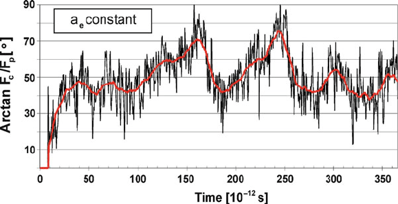
Figure 7.3 shows the course of the cutting force ratio for the simulation in Fig. 7.2.
The instantaneous tool forces, which will be newly calculated for every time step,
fluctuate intensively. Calculating a moving average of the force ratio over, e.g., 1,000
time steps cancels out the fluctuations and leads to a smooth course. After over-
coming the equilibration phase (no cutting forces), the first tool/workpiece contact
was made and the force ratio changed to an average value of 1 (¼arctan 45
)overa
period of about 20 ps (10
12
s). Besides smaller maxima and minima during the
observed total process simulation time, two gradually developing maxima in the
course of the force ratio appear at about 165 and 245 ps. Figure 7.3 sheds light on the
micro structural process that is related to the observed course of the force ratio.
Detailed information about the distribution of stresses and temperature in nano-
scale cutting are of high interest for science and manufacturing industry. So far
most of the MD results of cutting process simulations were presented as atomic,
discontinuous sets of instantaneous data at individual atom sites, such as snap shot
atomic positions, relative displacement and instantaneous atomic temperature.
Besides the limited meaning of instantaneous atomic temperatures and stresses,
looking at such large sets of 10,000, 100,000 or even millions of data is not practical
from a point of view of efficient data analysis. Furthermore, it makes any attempt to
compare MD results with, for instance, results from continuous mechanics difficult
Fig. 7.3 Course of the cutting force ratio Fc/Fp (after Rentsch in Davim and Jackson [1]). Used
with permission copyright ISTE-Wiley (2009)
7 Nanogrinding 307
if not impossible. Taking advantage of the possibility of improving the quality of
local values by calculating them as time averages over sufficiently long period of
time provides the means to obtain a deeper insight of the model and the simulated
process. Thus, aiming at macroscopic thermodynamic properties, suitable time
intervals for averaging these properties have to be identified. Simulations showed
that an average over about 1,000 time steps led in some cases to sufficiently stable
mean prope rties, but still provide a certain time resolution in order to study details
of the process. Considering the basics of MD and the physical nature of these
quantities, the results can now be represented in form of gradual distributions as so-
called contour plots, with a certain resolution in space as well as in time. The
representation of stresses and temperature in terms of continuous distributions
allows a direct comparison of continuous mechanics results and MD results.
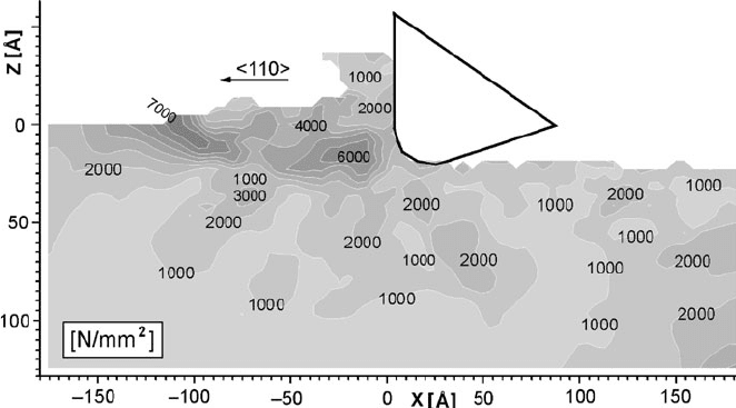
In Fig. 7.4 the calculated distribution of the maximum shear stress of the
orthogonal cutting process already shown in Figs. 7.1 and 7.2 is given. With the
help of this distribution it is possible to determine where stress concentrations
occur, how much the crystal structure influences the stress distribution, as well as
the material removal process, and what the differences are in comparison to
macroscopic, continuou s mechanics processes.
This also allows the determination of how the process influences the motion of
the workpiece and where new dislocations can occur, since areas of high shear
stress are potential sources for formation or extension of dislocations. Similarly also
temperature distributions can be calculated by adopting [7] to local volumes and
calculating time averages. As it will be shown in the following chapter, MD cutting
process simulations without the consideration of fluids lead to approximately
concentric temperature distributions, in which the hottest area is the chip area and
Fig. 7.4 Shear stress distribution in an orthogonal 3D MD machining model (after Rentsch in
Davim and Jackson [1]). Used with permission copyright ISTE-Wiley (2009)
308 M.J. Jackson and J. P. Davim
the chip root area. At the tip of the tool, the material is deformed at a high stress
level, whereby a lot heat it generated. Hence, the high temperature areas extend
from the chip under the tip of the tool, as one important source of heat generation,
to the areas of shearing. It should be noted here, that modeling the tool by rigid,
thermally not active atoms, does not enable the tool to conduct any heat. Therefore
the tool acts like a thermal isolator, which further supports a concentration of heat
in the chip.
Regarding the temperature distributions in MD cutting it should be further noted,
that in most of the published work only the thermal conductivity through phonons is
considered. The conductivity by electrons is neglected in such case, even though it
is one order of magnitude larger than that of the phonons. Hence, the presented
temperature levels as well as the local gradients would actually be lower than
shown. New algorithms were developed to describe thermal conductivity more
accurate by considering both, the electron and the phonon conductivity.
7.4 Three-Dimensional Machining Simulations
Two aspects of advances and recent developments in material removal process
simulation using MD will be explained in some more detail, which are the possi-
bility of carrying out complete 3D surface machining simulations and the consider-
ation of fluids. For abrasive processes the model requirements are higher than for
cutting processes, since orthogonal symmetry is not give n and a quasi-2D model,
cannot be applied. Besides the need to describe the geom etry of abrasives, the
model has to provide sufficient space for the deformation and chip formation of the
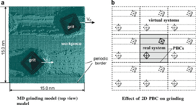
three-dimensional material removal process. Figure 7.5a shows a snapshot of a
molecular dynamics simulation to study material pile-up and chip formation in
abrasive machining as a function of shape and orientation of the abrasives.
The simulation in Fig. 7.5 considered two pyramidal grains with diamond
structure and two different orientations. The figure shows an advanced state of
the 3D grinding simulation using a model with more than 100,000 copper atoms
(the workpiece height was 6 nm). In several terms the simulation represents a high-
end state-of-the-art MD simulation of the grain/workpiece contact as the interac-
tions were based on an EAM potential function and the model considers two
abrasives that cut at 100 m/s through a workpiece over its whole length. Hence,
the periodic boundaries (for both directions of the horizontal plane) lead to com-
plete groove formation by the grits in a cutting direction and describe a model setup
with multiple grit/workpiece contacts that occurs in nanogrinding. By repeating the
complete groove generation with relative-to-the-cutting-direction shifted abrasives,
the machining of the whole surface can be realized. This provides the basis for 3D
surface roughness and residual stress analyses of completely machined surfaces at
realistic machining speeds (common grinding speeds range from about 5 to 80 m/s
and high speed grinding up to about 250 m/s).
7 Nanogrinding 309
Thorough the analyses of the chip formation, the elastic and plastic response of
the workpiece and process quantities in MD simulations have revealed clear and
consistent effects. For example, the machining speed has a direct influence on the
microscopic material removal process and the chip formation in MD simulations.
The resu lts suggest, that the sensitivity of the simulation results on the machining
speed is less strong than observed in experimental investigations. A possible reason
for this effect is, that the implemented boundary conditions and model settings have
a strong impact on the dynamics of the finite process model. However, significant
changes in magnitude of the machining speed lead to significant changes in chip
shape and formation mechanism. Further quantities of the process are affected due
to an increasing localization of the deformation process at high speeds. More direct
effects on the process simulation results show the depth of cut, the grit orientation
and the cutting edge radius. Hence, it is possible with MD to simulate the influence
of grain shape and orientation on the efficiency of abrasive processes. On basis of
bigger MD models, it will be possible to determine the energy dissipation by a
direct analysis of elastic and plastic work and the microscopic mechani sms that
determine the surface roughness in nanoscale machining processes.
7.5 Experimental Nanogrinding
The piezoelectric nanogrinding process is a process that relies on using a nickel-
coated ceramic material with microscale diamond particles bonded to it that are
cubo-octahedral in shape to machine nanoscale features in a variety of workpiece
Fig. 7.5 Snapshot of a full model length scratching simulation with two hard abrasives (after
360,000 time steps, 144 ps) (after Rentsch in Davim and Jackson [1]). Used with permission
copyright ISTE-Wiley (2009)
310 M.J. Jackson and J. P. Davim
materials. The diamonds are bonded to the piezoelectric material by gaseous
deposition, laser cladding, or directly bonding a porous tool to the material via an
adhesive paste. The process is executed by applying a known sinusoidal frequency
to the piezoelectric crystal in order to achieve a desired oscillatory displacement.
Rapid vibration of the crystal will allow material removal rates to be increased, thus
making it a nanomanufacturing process. The nanogrinding process is accompanied
by wear of the diamond grains, and the rate of this wear plays an important role in
determining the efficiency of the nanogrinding process and the quality of the
nanomachined surface. Wear mechanisms in nanogrinding processes appear to be
similar to that of single-point cutting tools, the only difference being the size of
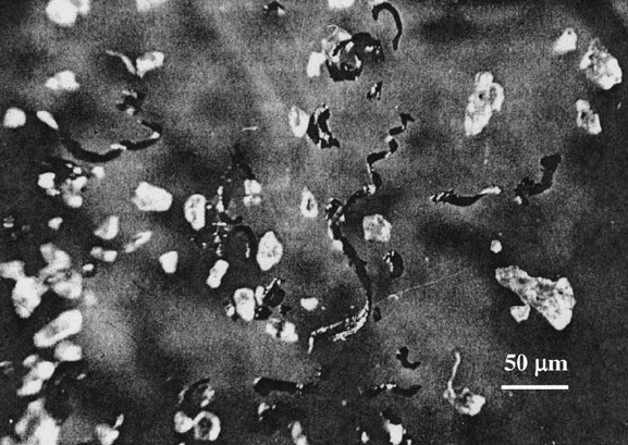
swarf particles generated. Figure 7.6 show s the arrangement of grinding swarf and
abrasive grains that have been lost during the nanogrinding process.
Figure 7.6 shows abrasive grains with blunted cutting edges (wear flats), and
abrasive grains with sharp cutting edges that are released from the surface of the
piezoelectric crystal before they have chance to grind nanoscale chips from the
surface of the workpiece. The process suffers with a loss of diamond grains even
when the interfacial adhesion between diamond and piezoelectric material is very
good. A more closely related process that has been reported widely is that of the
wear of probes used in atomic force microscopy [2, 3]. However, these observations
were purely experimental with no explanation of how to design probes that inhibit,
or retard, wear. A performance index used to characterize diamond wear resistance
is the grinding ratio, or G-ratio, and is expressed as the ratio of the change in volume
of the workpiece removed, Dv
w
, to the change in the volume of the diamond
abrasive grain removed, Dv
s
, and is shown in (7.1),
Fig. 7.6 Nanoscale grinding detritus showing blunt and sharp abrasive grains of diamond and
metal chips. Used with permission copyright Springer (2007)
7 Nanogrinding 311
G ¼ Dv
w
=
Dv
s
(7.1)
Grinding ratios for processes at the nanoscale have not yet been characterized.
However, the complexities of wear of abrasive materials at any scale lead us to
believe that the variety of different and interacting wear mechanisms involved,
namely, plastic flow of abrasive, crumbling of the abrasive, chemical wear etc.,
makes the wear of diamond at the nanoscale too complicated to be explained using
a single theoretical model [4]. The following analysis of diamond grains repre-
sented by loaded wedges assumes that grain fracture is the dominant wear mecha-
nism when grinding at the nanoscale using the piezoelectric nanogrinding process.
7.5.1 Analysis of Nanogrinding Grains
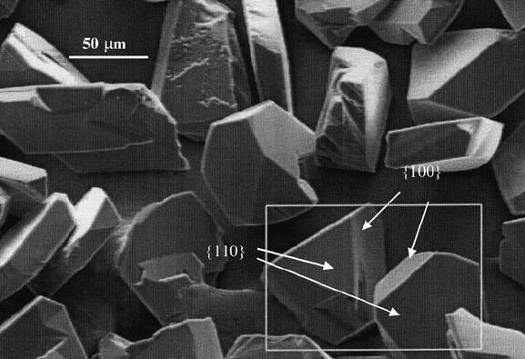
Diamond grains are blocky in nature and possess sharp cutting points prior to
nanogrinding workpiece materials. Figure 7.7 shows a collection of diamond
abrasive grains that have well defined cutting points that form a wedge at their
apex. When bonded into a strong matrix, these grains can be considered to be
representative infinite wedges.
An infinite wedge represents the cutting point of an abrasive grain in contact
with the workpiece material (Fig. 7.8).
Fig. 7.7 A collection of diamond grains showing cutting points located at their apex, and
locations of {100} and {110} planes. Diamond grains are approximately 60 mm in diameter.
Used with permission copyright Springer (2007)
312 M.J. Jackson and J. P. Davim
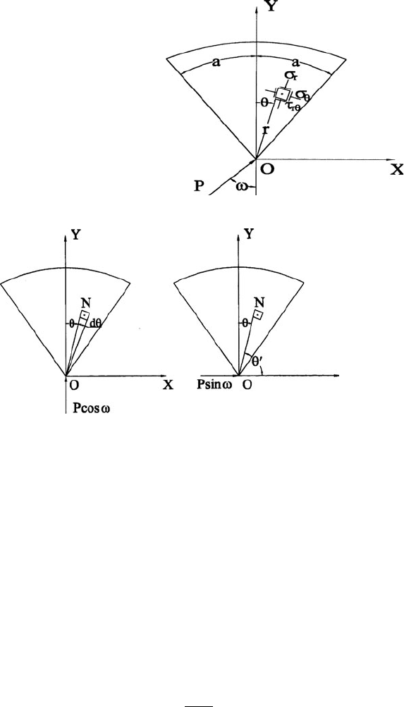
The wedge is loaded at the apex by a load P in an arbitrary direction at angle o to
the axis of symmetry of the wedge. Resolving the force into components Pcos o in
the direction of the axis, and Psin o perpendicular to that the stresses due to each of
these forces can be evaluated from two-dimensional elastic theory [5]. The state of
stress in the wedge, due to force Pcos o, can be obtained from the stress function,
’ ¼ C r y sin y (7.2)
where r and y are polar coordinates, or the point N in Fig. 7.9, and C is a constant.
The stress function yields the following radial, tangential, and shear stress
components,
s
r
¼2C
cos y
r
(7.3)
Fig. 7.8 The single-point,
loaded infinite wedge. Used
with permission copyright
Springer (2007)
Fig. 7.9 The single-point, loaded infinite wedge showing force components, and the point N
within the wedge at polar co-ordinates, r and y. Used with permission copyright Springer (2007)
7 Nanogrinding 313

s
y
¼ 0 (7.4)
t
ry
¼ 0 (7.5)
To determine the constant, C, the equilibrium of forces along the y-axis is:
P cos o
Z
a
a
s
r
cos ydA ¼ 0 (7.6)
where dA is an element of cross sectional area within the wedge. If, t, is the
thickness of wedge, then,
cos oP ¼
Z
a
a
2C
cos y
r
t r cos ydy ¼ 2Ct
Z
a
a
cos
2
ydy
¼ Ct 2a þ sin 2a½ (7.7)
Therefore,
C ¼
P cos o
tð2a þ sin 2aÞ
(7.8)
And,
s
r
¼
2P cos y cos o
r tð2a þ sin 2 aÞ
(7.9)
Note that the negative sign denotes that the stress is compressive. The state of stress
in the wedge, due to force Psin o, can be obtained from the stress function,
’ ¼ C
0
r y
0
sin y
0
(7.10)
Therefore,
s
r
¼2C
cos y
0
r
(7.11)
s
y
¼ 0 (7.12)
t
ry
¼ 0 (7.13)
Equilibrium of forces along the x-axis (Fig. 7.9) yields the following solution for
the constant, C,
314 M.J. Jackson and J. P. Davim