Indian National Committee on Large Dams. Design and Construction Features of Selected Dams in India
Подождите немного. Документ загружается.

96
Axrr
of
--9'30
Iop
-€L.
tE3:OZm-
__+t
r--8'53|n
F5-94-
.|n
C
.t-
: of
c
rong roi
I
et.
t8?:&
Horrf
cfiomber
4'57X5.O8
m
EL.l7{85rn
i
E=E+-IJ4!1o
[
__e
L.
t
67.64m
\-J.
PE.L.
tEr.74
m
\
r
lso.oz-
\ci.z
I
l€3X2'74nt
l?8:Q.?m
gL.il8.B7m
_Boctcr'cugpfils
right
side non-overflow
dam.
y
of 9 vents
of
size 3.05
m x
ft)
designed
to discharge
595
//-
o?'oo"
--ltt
-
la
169'l6m
vinl
lSlect'tined
I
Guidc
for
aorrgcncy
got.
g'46m
I
oir
wnttstcrt
liacdl
g
l.
o65
!EF
EE;
€.
L.
il659
n
€.75
\-'tr
6lOm
EL.r49.O5
dl
.'J-
AttumGd
tinc
cxcovolbn E.L.7O-71
m
O
lO
20 30 mrlrrt
B'i-eft
po.wer
block
Right
conol heod
sluice
btock
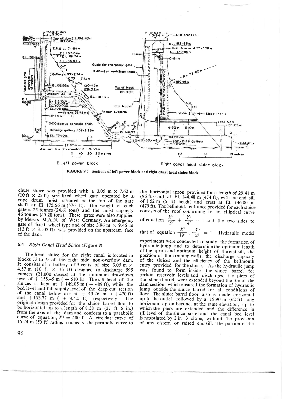
FIGURE 9
:
Sections
of
left
power
block
and right
canal
head
sluice
block.
chute
sluice
was
ovided with
a
3.05
m
x
7.62 m
(I0
ft
x
25
ft) sizC
xed wheel
gate
operated
by
a
rope
drum
hoist
shaft
ar
EL
175.56
ituated
at the top
of
the
gate
gate
is
25
tonnes
(
(576
f0.
The weight
of
each
6l
tons)
and the
hoist
capacity
).
These
gates
were
also
supplied
the horizontal
apgog.provided
for
a
length
af
29.41
m
(9^6
ft__6
in.)
at
El.
144.49
m
@74
ft),
wiih
an
end
siu
of
1.52-m
(5
f0
height
and
crest
at
El.
146.00
m
(479
tt).
The
bellmouth
entrance provided
for
each
sluice
consists
of
the roof
confirming
io
an
elliptical
curve
^X2Y!
oI
equatron
-in..
*
4.
:
1
and
the
trvo
sides
to
that
of
equation
#*#
-
t.
Hydraulic
modet
experiments
were
conducted
to
study
the
formation
of
hydraulic
jump
and
to
determine
the optimum
length
of the apron
and
optimur'
height
of
the
end
sill,
ih.
position
of the rraining
walls,
ihe
discharge
capacity
of
the
sluices
and
the
efficiency
of
the
bellmouth
entry
-provided
for
the
sluices.
As
the
hydraulic
jump
was
found
to
form inside
the
sluice
barrel
for
certain reservoir
levels
and
discharges,
the
piers
of
the
sluice
barrel were
extended
beyond
the to^e
of
the
dam section
.which
ensured
the
formation
of
hvdrauric
jump
outside the
sluice
barrel
for
all
conditions of
flow:
The
sluice barrel
floor
also
is made
horizontal
pp
10
the outlet,
followed
by
a 18.90
m
(6}ft)
long
horizontal
apron
beyond,
at
the same
elevaiion,
up
to
which
the
piers
are extended
and
the
differencb
jn
sill level
of the sluice
barrel
and
the
canal bed
level
is-negotiated
by
I in 3
slope,
without
the
provision
of any cistern
or raised
end
sill. The portibn
of
the
lO mclrcr
rf
West
Germany.
An emergency
ype
and
of
size
3.96 m
x
9.46
m
(13
ft
x
31.03
fO
of the
dam.
s
provided
on the
upstream
face
6.4
Right
Canal
Hefd
Sluice
(Figure
9)
The
head
sluice
blocks
7 3
to
75
of t
for
the ri-eht
canal
is
located
in
46
tonnes
(45.28
ton
by
Messrs
M.A.N.
gate
of
fixed
wheel
It
consists
of
a batt
4.57
m
(10
ft x
I
sluices
is
kept
at
bed level
and
full
su
cumecs (21,000
c
)
at
the
minimum
drawdou'n
level
of
*
155.45
m
+
510
ft).
The
sill level
of the
149..05 m
(
+
489
ft\,
while
the
of
the
canal
below
ply
level
of
the
deep
cut section
are
at
+143.26
m
(
1470
tt)
+
504.5 f0 respectively.
The
d for
the sluice barrel
floor to
from
the
axis
of
the
length
of 8.38 m (27
ft 6
in.)
dam
and
conform
to a
parabolic
curve
of
equation,
:
400
f.
A circular
curve of
connects the
parabolic
curve to
15.24
m
(50
ft)
radiu
+
153'92rn
sluice
beyond the
shutter line
is provided
with
a
semi-circular
roof.
The
sluice
vents
are
provided
with
fixed
wheel
gates,
electrically
operated
through
gate
shafts,
by
rope drum
hoists located at
El. 179.83 m
(590
ft).- As
these
are regulating
gates,
slide
plates
are
provided on
the upstream side
of
the
gate
shaft
to ensure
the effectiveness of the
seals
throughout
the
regulating range
of
the
gates.
The
gates were
manufactured
and
supplied by Messrs
Tungabhadra Steel
Products
Ltd.,
and
hydraulic
rnodel
studies
were
carried
out by
their
consultants,
Messrs
Neyrpic of
France in
their
laboratories.
Provision
is made
for
an
emergency
gate
operated
by
a
gantry
crane
moving
on top
of
dam.
7. Design
of Power Waterways
(Figure
9)
7.1
8
penstock
pipes
of
4.88
m
(16
ft)
diameter
with
centre line
at
El. 123.4
m
(405
ft), are
embedded in the
power
dam
blocks
16 to 23 at
the
left
flank, for
pur-
poses
of
porver
development.
Releases
through
these
penstocks
will
be
let into the
river below,
after
power
development, which
will
be
picked
up at
Prakasam
Barrage
as
Vijayawada
for
irrigation
requirements
of
Krishna
delta.
In addition,
3
power
sluices of size
4.57 m
x
11.58
m
(15ft
x 38 ft)withsill
atEl. 146m
{479
ft),
are
provided
in
the
right
non-overflow
section
of dam adjacent
to
the right canal
head sluices
to develop
hydro-power
with the
waters
that
will
be
drawn
into
the right canal
below
for irrigation.
7,2 The
penstocks
are embedded
horizontally
in
the
power
dam,
unlike
the
common
practice
of embed-
ding the
pipes
in an
inclined
way. This
method
facilitated
raising
the
power
dam
with
ease
up to
the
sill
level of
the
penstock
pipes.
The
other
advanta-ees
are that
the
length
of
pipe
embedded
irr
8. ConstructionContractAdministration
8.1
)[ajor
Corttracts
There
\\
ere
no
major
contracts
on
the
contruc-
tiorr of the dam
proper,
viz.,
placement
of
maso-
nry and concrete.
The
only major contracts engaged
on
the
construction were
for the
fabrication
and
erection
of
gates
and
hoists
for
the various outlets
provided
in
the dam.
The
spillway
crest
gates
and
the
dam
masonry
is
smaller
resulting
in reduction
in
the
immediate
cost
involved
and thlt the
extension
The
intakes
are
controlled
by
high
head
gates
of
!I.d
wheel
type
of size 4.04
m
x
lit
m
({iq
n x
25.30 ft)
on
the-upstre.am
face
of
the
dam,
operated
by hydraulic hoists.
These
gates
are intended-
to
be
quick
acting type with provision
for
remote
Control
from the
power
house. The gates
and hoists
were
lupplied
by
Messrs
M.
A.N.
of West
Germany.
Each
gate
weighs
about
50 tonnes
(49.21tons)
aria
the
hoist is
designed
for
a maximum
normal
capa-
city of
70
tonnes
(68;9
tons).
The
hoist is
also
checked
lowered into
position
by
means
of
a
travelling
7l.Iz
tonnes
(70
tons)
gantry
crane.
provided
on
top of
darn.
Purt
lll-Construetion
hoists
were
furnished
by
Messrs
Jessop
&
Co. of
Calcutta.
The
penstock
gates
and hoists, the
chute
sluice
gates
and hoists'
and
the irrigation-cum-diver-
sion
tunnel
gates
and
hoists
were suppiied
by
Messrs
M.A.N.
of
West
Germany
through
Messrs
Escorts
Ltd.,
Delhi.
The right
canal
head
sluice
gates and
hoists
were
furnished by Messrs Tungabhadra
Steel
Products Ltd.,
in
collaboration with
Messrs
Neyrpic
of
France.
The
prestressed
concrete
bridge
built
across
the river
below the
dam
line
is
another
.esd.f
'"-j^4'
97
structure
that
was
constructed
on
a major
contract
by
Messrs
Andhra
Cement
Construction
Company,
Madras.
8.2 Minor
Contracts
negotiation
stage,
the
mukhaddams
would
further
reduce
their
already
competitive
rates. The lowest
negotiated
and accepted
rate
was offered
to
all
the
other
mukhaddams
as
well
and
the
work
distributed
to
all
of
them.
In
this
way,
the work
was
carried
out
quickly
at
economical
rates.
This
system of
negotiation
and
distribution of
work among
all the
bidders was particularly
adopted
in road
work, quar-
rying of
rubble
and loading of sand
into
lorries,
etc.
Considerable
economy was
achieved
by adopting this
method
as the
rates
were very competitive
and
reasonable
and
the
work
at the
same
time
was
got
done earlier
than
one could
expect
of a
regular
con-
tractor.
8.3 Government
and Contractor's
Organisation
'
The damsite lay
in a
hilly tract
of
thorn
scrub
jungle
in the interior
and
was a haunting
ground
for
tigers
and other
wild
animals.
The nearest town,
Macherla, was
2t
km
(13
miles)
away.
The
first
and
foremost
tasks
involved
before
taking up
work
on
the
dam
were
the
formation
of approach roads
and
bridges,
etc.,
to
the
damsite,
construction
of
camp
buildings
providing
protected water supply
and
electric supply,
and
setting
up of
medical,
public
health.
educational,
banking,
postal
and
telephone
98
truction
sluices,
drilling
and
grouting,
laying of
masonry,
R.C.C.
work
forgalleriesand
fbundltion of
left earth
dam,
in
addition
to
excavation
of founda-
tions. The
services
circle
looked
after construction of
earth
dam
also.
As
the
dam
rose
in height, trestle
bridge
and
monotower
cranes
were
erected
on the
dam.
In addition
to laying
of
masonry,
new works included
embedment
of
penstock
pipes
and erection
of trash-
rack
_
structures,
borin_e
of
irrigation-cum-diversion
tunnel,
construction
of
various
sluices in
the
dam,
laying
concrete
for
spillway,
bucket
and
sluices,
etc.,
and
erection
of
gates
for
various openings.
An
addi-
tional
mechanical
circle
was
formed in
the
year
l9G4
to
cope
up
with
all the
increasing
mechanical
works.
The
number
of supervisory technical
staff
engaged on
the
dam
construction
was
of
the order
of
650.
-
Medical
and Public
Health:
About 45,000
skilled
Labour
and
Lobour
Welfare
: All
the labour
engaged
on
various construction
activities
on the dam
and allied
works
was
accommodated
in
four labour
camps on
the
right bank
and
three
on the
left
bqlk, with
one more
at
the Bandlakarva
quarry
site,
a little
far
away
on
the
left
bank.
Medical
and
health
servrces,
community centres
and night
schools,
etc.,
were
established
for
ihem.
Other
facilities
provided
included
canteens,
first
aid
centres,
rest
sheds and
creches,
etc. A Labour
Officer
was
appointed
and the
labour
was
well
looked
after and
harmonious
relations
existed
between
the labour
and
the contractors
on
tion was
brought
to
completion
without
any major
trouble
or unrest.
Audit
and
Accoutlts
: To assist
the
eneineers in
dealing
with
the
financial, payment
and
a"ccounting
problems,
one
independent
pay
and
accounts
organi--
sation
was
constituted,
headed by
a
Financial
Adviser
and Chief
Accounts
Officer of
the
rank
of Accountant
General
and was
incharge
of
compilation
of
project
accounts
and payment
of
bills
after
pre-check.
The
project
accounts
were
made
available
for concurrent
audit to
the Accountant
General
for
rvhich
separate
staff
headed
by
a
Deputy
Accountant
General
was
stationed
at the
damsite
alongside
the
accounts
staff.
With
the
introduction
of
this
pre-audit
system, the
Executive
Engineers
and the
Assistant
-
Engineers
were
relieved
of
the
duty
of issue
of cheques
and
Law
and
Order
and
Vigilance:
The
headquarters
of
the
Deputy
Superintendent
of
police
was iocated
at
the
damsite
with
adequate
staff
in
the
various
colonies. vigilance
Inspectors
working
under
a
vigilance
officer
checked
pilferage
and
theft
-of
materiaJs
not
only
from the variouJ
stores
but
also during
transit
u-nd
kept.
the
department
informed
of
any
unsocial
elements
in the
township.
8.4
Land
and Land
Rights
and
Rehabilitation
In order
to
bring
down
the
cost
of
land
acquisition,
the
ployisions
of
the
Nagarjunasagar
project
Land
Acquisition
Act,
1956,
freezing
the land
values
at
the
level
prevailing
on
1
July 1953
were
made
applicable
to
the
submergence
area
under
the
reservoii.
How-
e-ver, as a
generous
gesture
to
the landless
poor,
even
the encroachers
on
Government
lands
who
were in
continuous
possession
and
enjoyment
for three
years
were
given
compensation
at the
rate
of
one-third of
-the
market
value
of
the
land.
57
villages
including
hamlets and
thandas
convering
an
area
of more
than
12,140
ha
(30,000
acres)
with
a
population
of 24,500
were
subrnerged
under
the reservoir.
24 suitable com-
pact
blocks of
reserve
forest
areas measuring about
ll,290ha(27,000
acres) were
unreserved,
cleared
of
forest
growth
and
allotted
to
the
displaced families.
This
fresh area was
transferred,
free
of
cost, first
to
the
"+JtY#'"t+Sf
99
project
and
subsequentry
ro
the
Revenue
Department
subject,
however,
to
airy
revenue
deriveJ
fro,n
the
assignment
of
land
being
iredited
to the FoirJo.prii-
ment.
The
concession-s
granted
to
the
dispraced
famiries
are
enumerated
below
:
(d)
Free
transporr
to shift
the
families
and
their
belongings'
Those
who
shifted
uv-trr.rserves
were
paid
Rs.
1.09
per
km
(Rs.
l.?5 per
mile).
(ii)
Permission
to
take
the
building
materials
free
of
cost,
even
after
receiving
.J*prniutlon,
for
constructing
houses
at
the'rehabilitarion
centres.
(ttt)
Allotment
of 4
ares
(l0cents),
free
of
cost,
to
each
family
for
house
sire
at
ihe
rehabitituiion
centres.
(fr,)
An
ex
gratia
amount,
subject
to
a
maximum
of
Rs.
300.,
1o
eaglr^family
receiving
u .orp.nr"_
tion
of
Rs.
500
or
l-ess.
to mike
up-rhe
total
amount
to
Rs.
750.
(y)
A
free.grant
of 2.O2ha (5
acres)
of
dry land
or
l
.01
lt*
Q.i
acres)
of wet
land
to
every
displaced.famity
owning
land
of
g.09
-
ha
(20
acres)
or
less.
(vi)
A
loan
of
Rs.
100
and
a
grant
of
Rs.
r00
to
each
dispraced
family
havinf
ress
rhan
qo.+l
t
a
(l_00
acres),
ro
meei
the
cost
of
reclamation
of
the
agricurturar
rand
allotted
to
them
in
the
rehabilitation
centre.
(vif)
Pucca
drinking
warer
wells
in
the
rehabilita-
tion
centres
at
the
rate
of
one
foi
lvery
50
families.
(viii)
lnternal
roads
in
the
village
site,
approach
road
to
the
rehabilitation
centre
frbm
the
existin=q
main
road
and village
schools,
temples,
chavadies-cum-community
ientres
ana-
ottre,
common
facilities,
ifl
submerged
in
the
old
village,
at the
cost
of
the projeft.
(ix)
Pernrission
to
the
displaced
families
to
cultivate
their
lands
in
their
oid
viilages
tirr
trr.v
were
submerged
in
the
reservorr,
on
payment
of
Iease
amount
equivalent
to
land,.u!ni..
8.5
Constructiort
Support
Facilities
(l)
FecrLrrres
FoR
Suppr.y
op
MareRrALs
Cement
: A
new
cement
factory
was
erected
at
Macberla,
at
a
distance-"i
uuout
24
km (r5
miles)
from
the
damsite,
where gooOlln'estone
deposits
are
100
available.in
plenty
for
the
manufacture
of cement,
to
cater
ro
the
needs
of
the
project-
io-ru-ri.
-i*depart-
mental
metre galge
railw'ay'rin.
r"r-iuii
.onnriti"g
Macherla
to
the
Righl
Bank'on
Lanka
ffi;-Hlir
uni
cement
was
conveyed
in
60
bulk
""**i
wagons.
Arrangements
were-
made
ut
thr
railwav
terminus
to
unload
cement
direc-rly
into
uuit
";;;;;r"";;il;:
which,
in
turn.
conveved
the
cemeni-
to
the
various
batching
plants
on
righ1
-and
feft
-flanfcs.
These
bulk
cement
carriers
were
of
thorny
craft
ivp.
fuilv-
.quipp.A
*itf,
lir:9rnp-rglsgrs
capabte
of
tiftfig
cement
to
a
nJilUt-oT
22.86
y
(71_{t)
at
the
rate
of
ZO.1Z
tono.,
tZO
ilos)
p.,
hour.
In
addition,
rwo
silos
oilSl6
t;;;;r'?i,oooi"iil
,cgRacitv -each
yele built
near
the
roti
-ol'l'ie
ranka
Mgtg
Hill,
such
that
cement
-could
u.
u'roua.a
into
and
drawn
frory
these
sitos
into
trucks-bt
;;;;itv
and
conveyed
to
the
batching
plants,
in
"ise"ihe
bins
at
the
batching
plants
*ere
filt.
surkhi:
A.
ba,
milr
was
erected
at
the
damsite
to
manufacture
4n. .
grained
surkhl-;;;a;;-'i"
ttre
required
specification
ror
aomiiiur.'ii'.iii.ot'-ortar
and
cemenr
concrete,
from
the
clay;A;;illvailable
in
plenty
in
the
vicinity.
Sand
: Trvo
sources
of
sand
were
located,
one
in
ream
at
a
distance
of
about
eam
of
the
damline
and
the
Liver
at
a
distance
of
about
re
north
of
the
damsite.
In
of
the
high
masonry
coffer-
rsiderable
quantity
of
about
of
sand
was
depoiitea
on
the
of
about
4.90-km
(3
miles)
right
bank
and
this'deposit
approach
road
was
laid
t
the
right
bank
at
about
_
sand was
collected,
conveve
construction
of
dam.
Sir
with
regeneration
every
yeal
of
construction
of
the
dam
were
laid
to
the
site
for
transport
of
sand.
As
these
approach
roads
were
riabre
for
submersion
under
the
reservorr,
transport
of
sand
to
the
batching
plants
was
carried.out
by
means
of
ordinary
lorriesl'fn.
sand
-was
collected
at
one prace
by
means
of
a dozer
and
loaded
into
the
lorries
iranrarty
uy
means
.r
"r
Emco
loader.
A
fleet
ot
45
to
so
ioriiil;;t.il'rortn,
nt'
as
well
as by
the
contrac_
Lransport
about
1,640
cu
m
ay
working
round
the
clock.
nstruction
of
the dam,
rvhen
ised,-
the
peddavagu
sand
roach
road
were
submerged
sand
from
Haria
River
-J."il1'3,ltJnitji
:Hilft';ffi1
Another
approach,
road
rvas
raid
to
ihe
Haria
siie
for this
purpose
and
sand
conveyed
by
means
of
trucks. Road
transp.ort
was
preferred
to
the
othet
o,ooi.
of- ,t"or-
port
by
rail
or
rope
way
here
uiro,
in
view
of
economy
"+tH:tlitr&e-**.-
.*
ffi-
rn
cost, greater
flexibility
in
operation
and
facility
to
rncrease
the ourturn
by
entrusting
part
of
the woik
to
contractors
in
the
case
of
road
iransport.
Again,
mechanical
equipment
such
as
loaders,'
showels-and
belt
conveyo{s
could
not
be
used
for
toaoing
sana
into
the
trucks
inasmuch
as
the
regeneratio-n
of
sand
in
the river
fluctuated
very
wide)y
from yiur
to
y.u.
and was
spread
gveT
?
large
area.
Hence
toaift
operations-
were
carried
out
with
rn"nuil-lubour.
A
fleet of
about
40
trucks
was
utilised
to
ronu.y
1,416
cu m
(50,000
cu
ft)
of
sand
daily.
Rubble:
All
the
stone
required
in
the firsr
srage
construction
of
dam
was
obtained
from
the
islarid
quarry
situated
about
3.2
km
(2
miles)
upit.ea-
of
daglfe
Approach
roads
were
taid
by
tn.
O.jurument
and..the quarrying
and
conveyance
oi
stone
was
done
DJ
rneJob
work
contractors
engaged
for
the.construc_
tion of
masonry
with
_
the
mJrtir
suppried
ai
site
by
the department.
Tlg
dgpgtment
madi
some
arrange-
ments
.for
supply
of
jackhammers
and
comprisseO
air
tor
drrllrng
to
the contractors,
but
the labour
resorted
to the
old
methods
of
hand
driils
to
wbich
they
were
accustomed.
conveyan_ce
was
done
by
means
of
ord.inary
lorries.
A
fleet
of
over
76
loiii.,
was
maintained
by
the
contra
about
2,830
cu m
(1,00,000
the
day
shift
of 8
hours
witl
I,400
for quarrying.
Ar
submerged
on
raising
the
constnrction,
fresh quarries
were
tapped
at
Bandla-
karva
located
at
a distance
of
abouiit.z
to
rz.g
t,n
g
to
8 miles)
to
the north
of
the
damsiie.
About
50
percent
of
the total
work
involved
oo
irtr
dam
in
re
with
the
stone
obtained
arry.
There
was
sufficient
Iffi.'ilfff;
'liffff"J:
ror
operation
*ppried.
o;tl"'8#tff#3i::fff
t;
149
cu.m/m
(1,600
cf,m)
c-apacity
instalred
iru..nt.ur
pla,ce
in
the
area.
Blasting
*ir
donq
*itrr getutine
and
electric
detonators.
A
Jeparate
laboui
ca"mp
was
established
at site
ro
accommodate
the
labour
enlaged
on
this
quarry.
The
sqge
system
adopted
for
the
conveyance
of
sand
from
Halia
River
was
idopted
for
conveyance
of
stone
from
Bandlakarua
quarry
for
the
same
reasons.
A
fleet
of
over
100
Leyhnd
irucks
of
7.62
tonnes
(7+
tons)
capacity
was
ensased
for
conveyance-
Loading
and
unloading
of
thJvehicles
rvas
carried
out
by
manual
labour.
T6
keep
this
huge
fleet
of
lorries
in working.condition,-r
*o'.tiirop
*us
established
at
site
for
serviiing
and
repairs.
(2)
Fncnrurs
on
SroRss
In
order
to
ensure
prompt
and
regular
procurement
and
flow.of
supplies
to
the
variou,
uiit,
"f;h;
p.oje"t,
a
-
central
store
was
maintained.
About
30,00b
iiemi
of
materials
were procured
and
kept
in
rtot.r-
io
.ate,
to
the
needs
of
thb
severar
consurning
diuiiioni.
This
worth
about
Rs.
22
crores.
system
was
evolved
to cope
j"
?','*
1T::I;,
"
ll;
*?,1:
::
(3)
WonKSHop
Fncnrrrrs
r
concrete
and
bearings
for
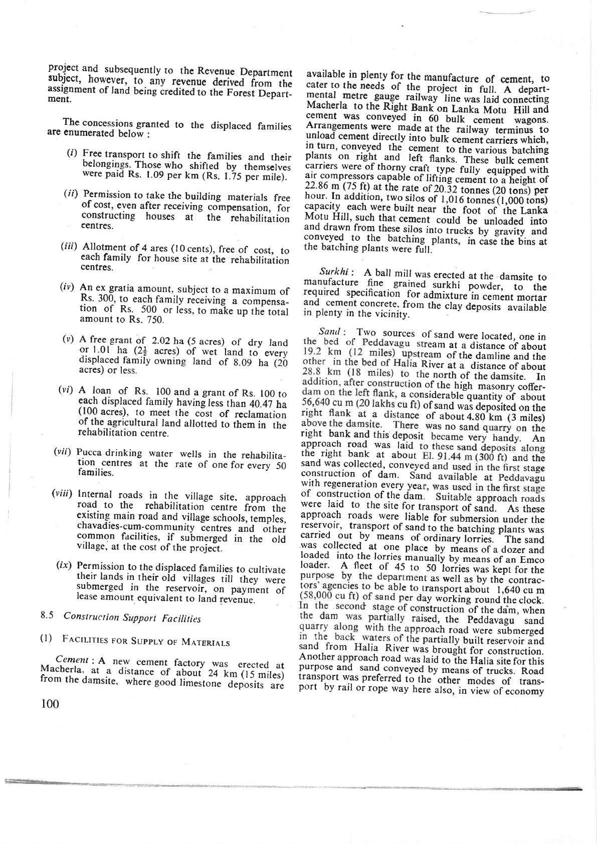
9'
construction
of
Dam
and
Appurtenant
structures
(Figure
10)
9.1
Diversion
and
Care
of
River
(I)
Mesouny
ConrnRolu
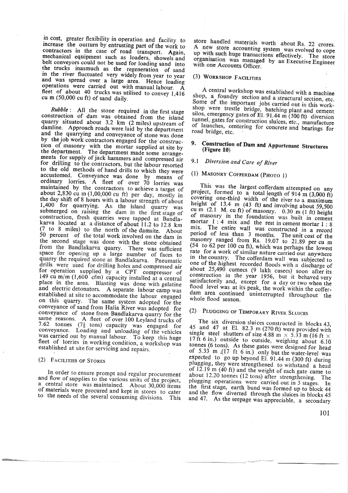
(pnoro
l)
This
was
tf.
largest
cofferdam
ajtempted
on
any
project,
formed
ro
i
total
t"ngifi
oT-gil?i1,000
ft)
cove-ring
one-third
wicith
of
the
'ver
to
a
maximum
heighr
of
13.4
I .(4r
rt)
ano
in;i;id;Jui
ss,soo
cu
m
(2.1
M.
cu
ft)
of
masonry.
O.:o
"m
A
Fr)
rrrigt,
of
maso_nry
in
.the
foundation
was
built
in
cement
mortar
I
: 4
mix
and
the
rest
in
".-rni.ortar
t
:
g
mix.
The
entire
wail
was
constructed
in
a record
period
of
less
-thro
3
months-
The
unii
coit
of
the
masonry
ranged-
from
Rs.
19.07
to
2l.gg
pr.
.o
*
(54
to
62
per
100
cq
fr),
which
was
perh"p,
tf,,
Iowest
rate
for a
work
of
similar
nature
"u.ii.d
dut
anywrrere
in
the
country.
The
cofferdam
*;il
;;,
,hilted
to
one
of
the
hi_ghest
recorded
floods
*itn
u
iir"diarg.
or
about
25,490
cumecs
(9
rakh
cusecs)
soorl
after
its
construction
in
the year
1956,
but
lt
u.trau"o;.ry
:atisfactorily
and,
.except
for
a
day or
t*o
*ir"o
tt,
flood
level
was.at
its pe'ak,
the
work
within
the
coffer-
dam
area
continued
-unirterrupted
tt
iougt
out
the
whole
flood
season.
(2)
PruccrNc
oF
TsMponany
Rrven
SI-urces
The
six diversion
sruices
constructed
in
brocks
43,
4s
and
47 at
EJ
82.^3.m
(27oft);;;;iiouia.a*itr,
srlgle
steel
shutters
of size
4.gg
m
x
j.fj
,n-iro
rt
*
lTft
6
in.)
outsid.e
t_o
outside,
weighing-"ir,irt
6.r0
to^n1e1J6
tonp)-.
As
rhese gates
were
tesr!.'ea'io.
neaa
of
5.13.
m
.(17
ft
6 in.).'only
but
the water_level
was
:T.?::l:q 1? 99
up
beyond
Ei
s1.44 m
(roo
fij
au,ine
pruggrxg,
th€y
were
strengthened
to
withstand
a head
or I
z. r
9
m
(4U
tt)
and
the
weight
of each
gate
came
to
about
12.20
tonnes (12
tons)
uTt..
strengthening.
The
p.lugg^ing
operations
were
carried
;ri;;-l-;iu*-.r.
In
the,
frst
stage,..earth
bund
was
form.a
"p
io-8ilct
++
an.'
tne
flow
drverted
through
the
sluices
in
brocks
45
and
47.
As
the
seepage
was
ippreciaute,
u--r..Lnaury
101
-
t--€t'"'
1-
t
'Pn'
Power
dom
l2l.9m-
{;";"*,f:Jfil,-l=-.f
Non
over-flow
29.5rn
F-n6
---f.Spill-woy
471.0
m-
r
I
hi non
over-flow
553.cl
m--.<l
of rood-woy
tB+.40
m
3'O x 4.6
right
conol heod
sluices
9 nbs.
INDEX
184.40
180.o
t70.o
t60.o
t50.o
t40.o
t30.o
r20.o
roo.o
90.o
80.o
700
60.96
4.9m
5
o
L
t
o
e
E
oE
o o
o
3Fj:1""..,3"on
.o
xxF--
r'
r
i1960
-___-_
,t
s
il96l
606---
D
t'
"1962
,iiooxx
"
a
"t963
Progress
lo end
m
of
Jine
1964
Prooress
fo end
--'-'-of
Juno
1965
'
'Prooress
to eniJ
x-x-x-
of
J-une
l9b6
Progress
lq end
of
Jude 1967
Progress to eod
xxxxx'of
June'
'tg6g
i,rogress lo end
o
f
Jun'e
1969
M Monotower
cron€O
lO
?O 3Om
O tOO 2OOm
t-L--t-.|-.J
Vertlcol
Horlzonlol
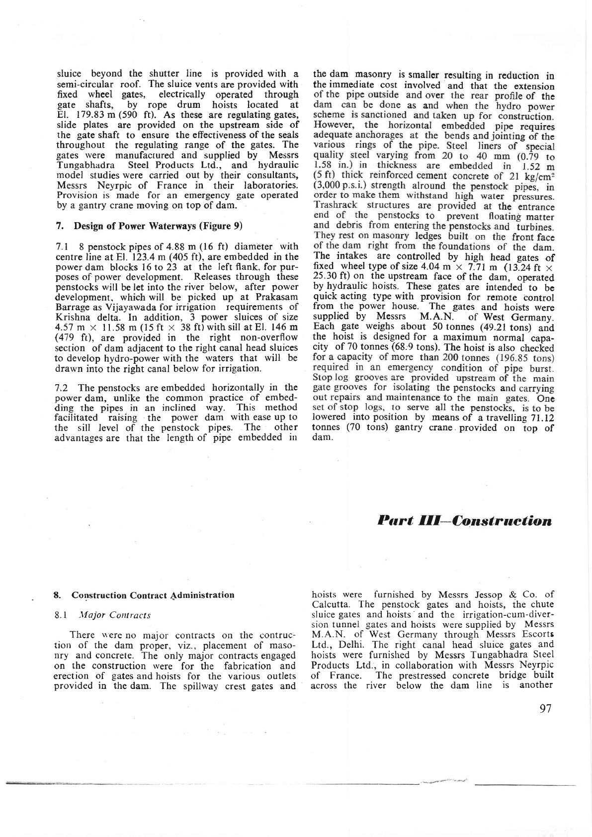
FIGURE
10
: Progress
of
construction.
l02
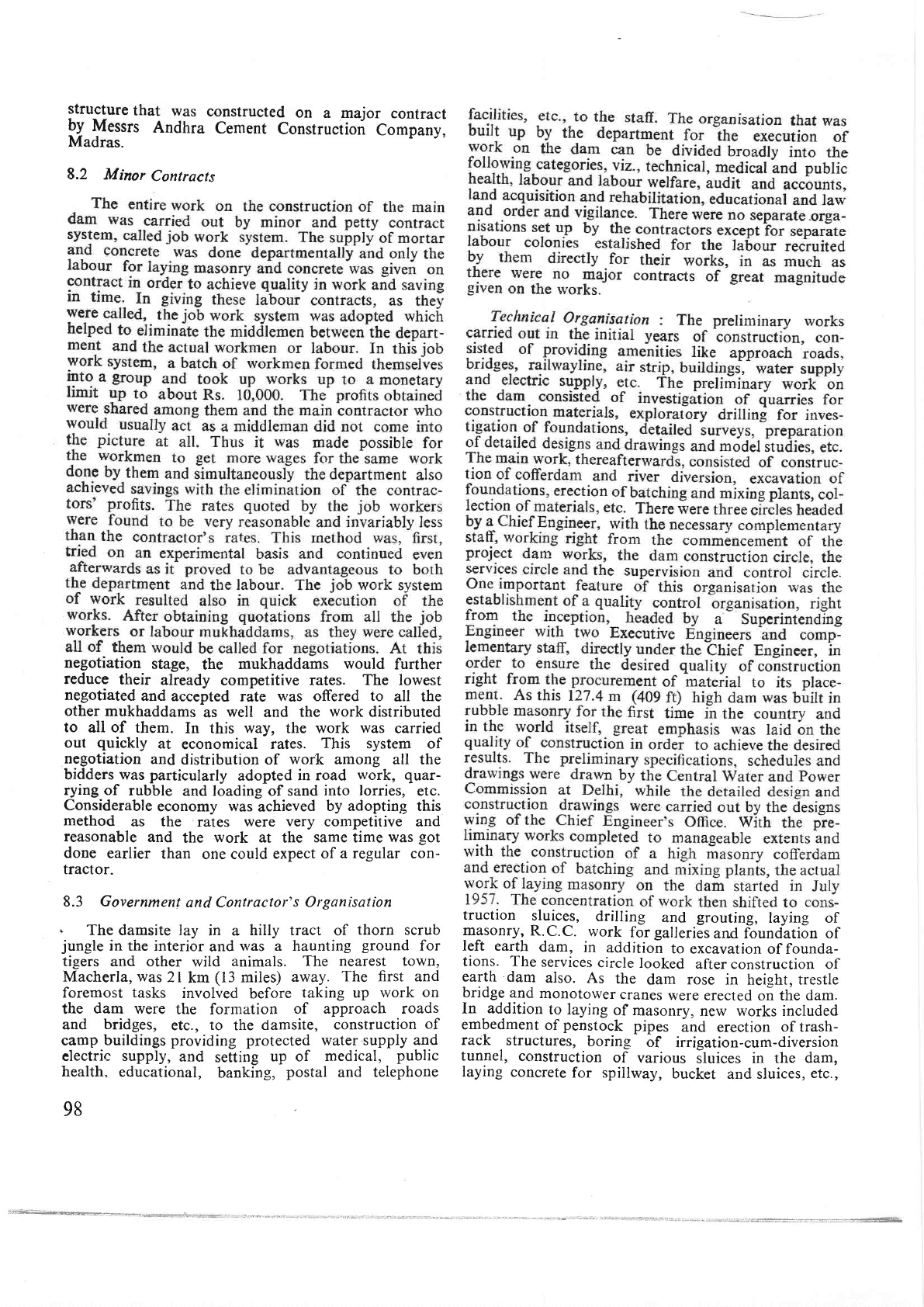
PHOTO
I : Work
in
progress
in
the
masonry
cofferdam
area
on
the
left
flank.
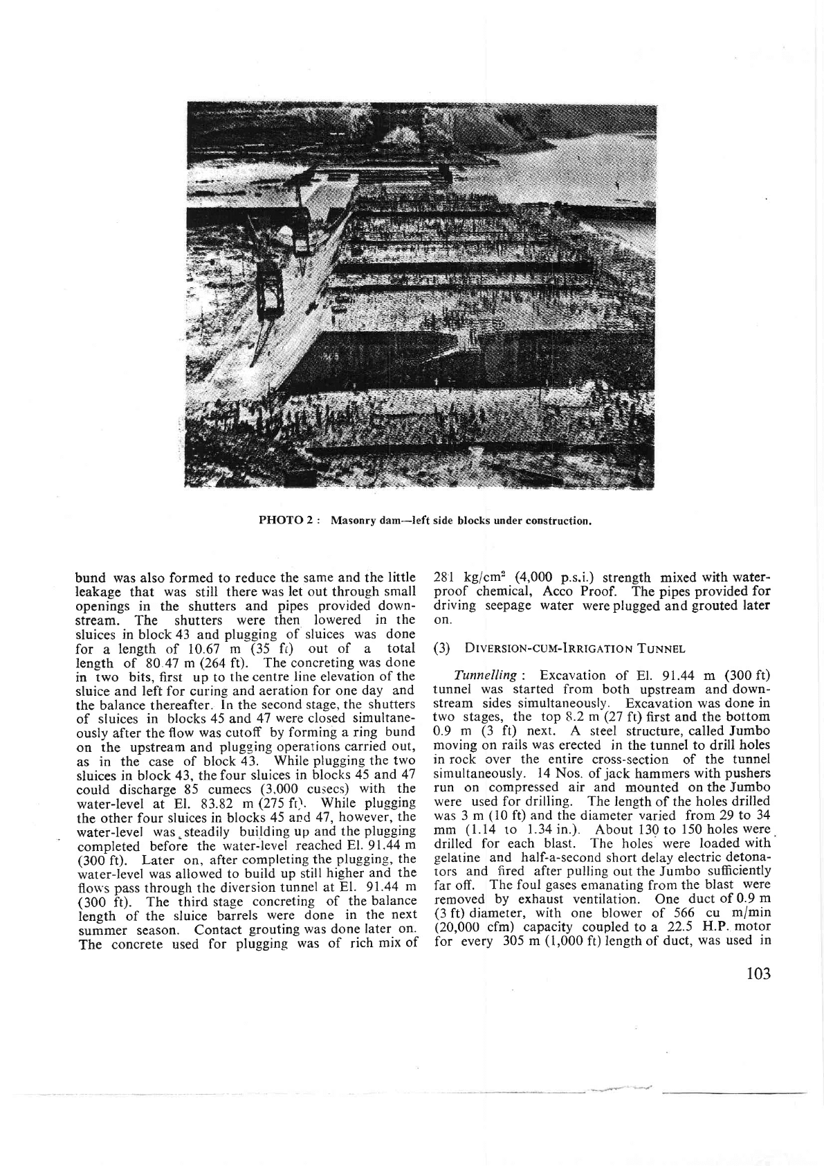
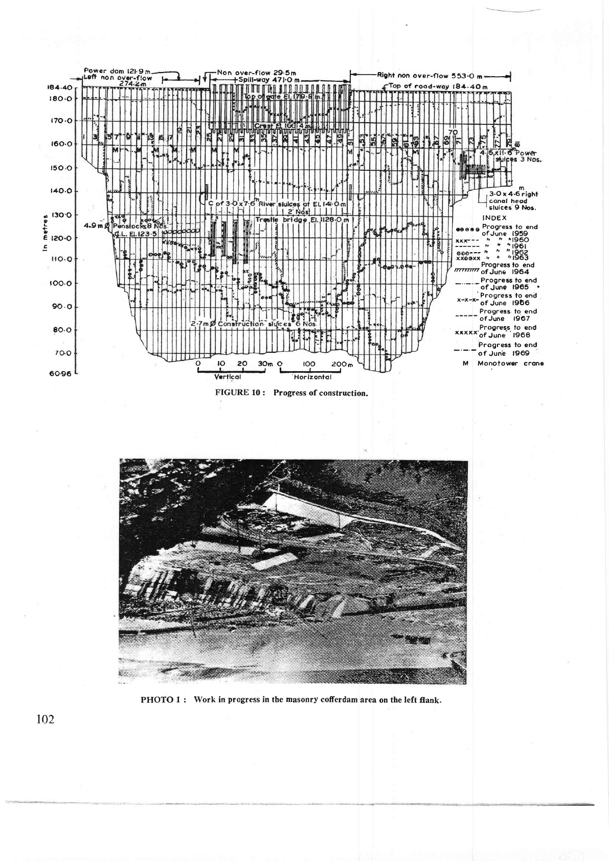
PHOTO 2
:
Masonry
dam-left
side
blocks
under construction.
bund was also formed to
reduce
the
same
and
the
little
leakage
that
was
still there
was
let
out through
small
openings in
the
shutters
and
pipes provided
down-
stream. The
shutters
were then
lowered
in the
sluices
in
block 43 and
plugging of sluices
was done
for
a
length of 10.67
m
(35
fi)
out of a
total
length of 80 47
m
(264
ft).
The concreting
was done
in
two
bits,
first
up to
the centre
line
elevation
of the
sluice and
left
for curing
and
aeration for
one
day and
the balance thereafter.
ln
the
second stage,
the shutters
of
sluices
in blocks 45 and
47
were
closed
simultane-
ously
after the
flow was cutoff
by forming
a ring
bund
on
the upstream and
plugging
operations
carried
out,
as
in the case
of block
43.
While
plugging
the
two
sluices in
block 43, thefour
sluices
in blocks
45 and
47
could
discharge
85 cumecs
(3,000
cusecs)
with
the
water-level
at
El.
83.82
m
(275
ft).
While
plugging
the
other four
sluices in blocks
45
and 47,
however,
the
water-level
was.
steadily
building
up and the
plugging
completed
before
the
water-level
reached
El.9l.44m
(30Oft). Later on, after
completing
the
plugging,
the
water-level
was
allowed
to
build
up still
higher
and the
flon's
pass
through the
diversion
tunnel at
El. 91.44
m
(300
ft).
The third stage
concreting
of the
balance
length
of
the
sluice barrels
were
done in the
next
summer
season. Contact
grouting
was done
later
on-
The
concrete
used
for
plugging was of rich
mix
of
281 kg/cme
(4,000
p.s.i.)
strength mixed
withwater-
proof
chemical, Acco
Proof.
The
pipes provided for
driving seepage
water
were
plugged
and
grouted
later
on.
(3)
DrvrRsroN-cuM-lRRrcATroN
TuNNel
Tunnelling :
Excavation
of
El.
91.44
m
(300
ft)
tunnel was
started
from both
upstream
and
down-
stream
sides
simultaneously.
Excavation was
done
in
two stages, the
top
8.2
m
(27
ft) first
and the
bottom
0.9
m
(3
ft) next. A
steel
structure,
called
Jumbo
moving
on
rails
was
erected in
the
tunnel
to drill
holes
in rock
over
the entire
cross-section
of
the
tunnel
simultaneously.
14
Nos.
of
jack
hammers
with
pushers
run on compressed
air and
mounted on the Jumbo
were used for
drilling.
The
length
of the
holes
drilled
was
3
m
(10
ft)
and
the diameter
varied
from
29
to
34
mm
(1.14
10
1.34 in.).
About
130
to
150 holes
were
drilled
for each
blast.
The
holes were
loaded
with'
gelatine
and half-a-second
short delay electric
detona-
rors
and
fired
after
pulling
out the
Jumbo
sufficiently
far
ofl.
The
foul
gases
emanating from
the
blast
were
removed
by
exhaust
ventilation.
One
duct
of 0.9
m
(3
ft)
diameter,
with
one
blower
of
566
cu
m/min
(20,000
cfm)
capacity
coupled to a 22.5
H.P.
motor
for
every
305 m
(1,000
ft) length of
duct,
was
used
in
103
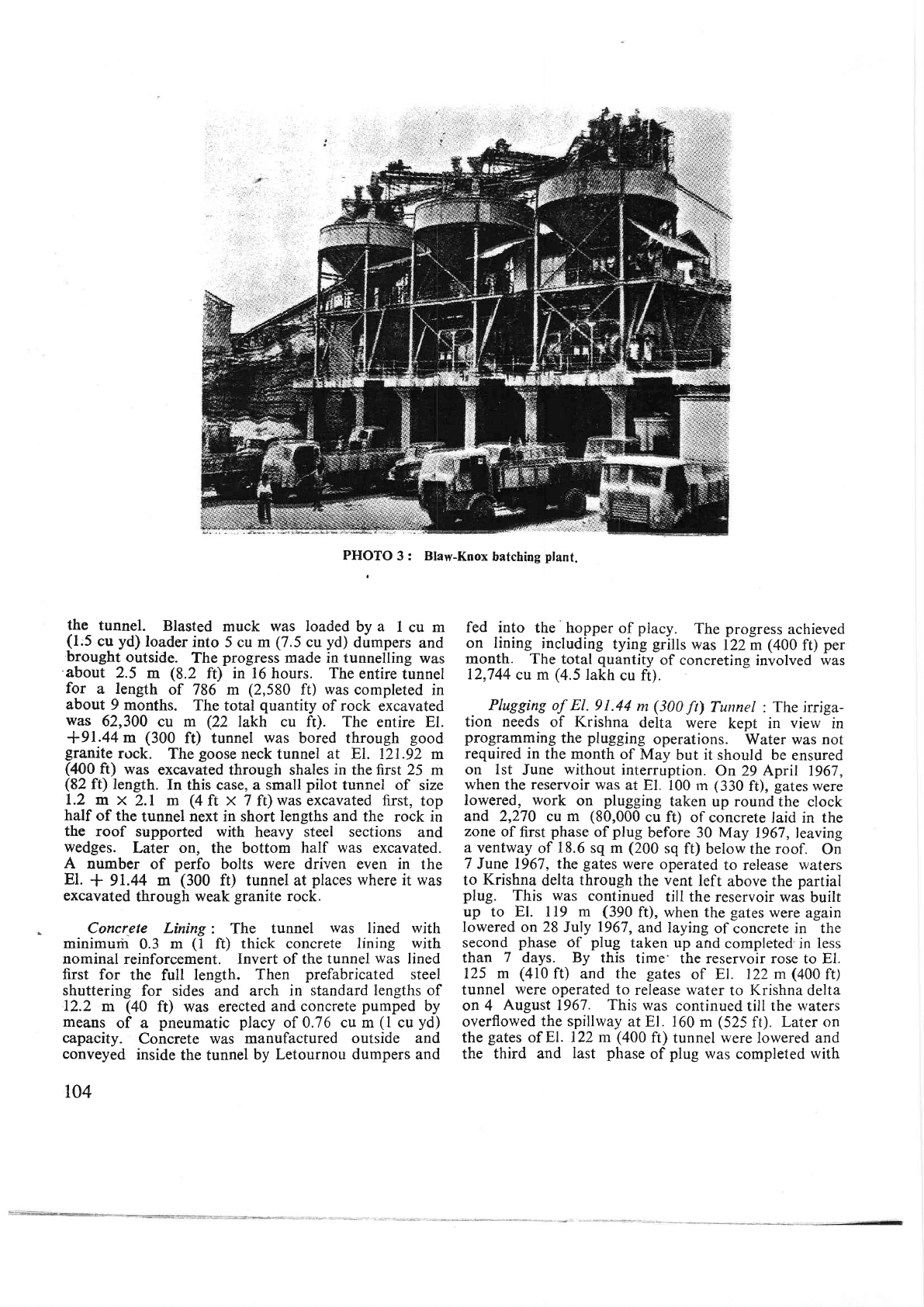
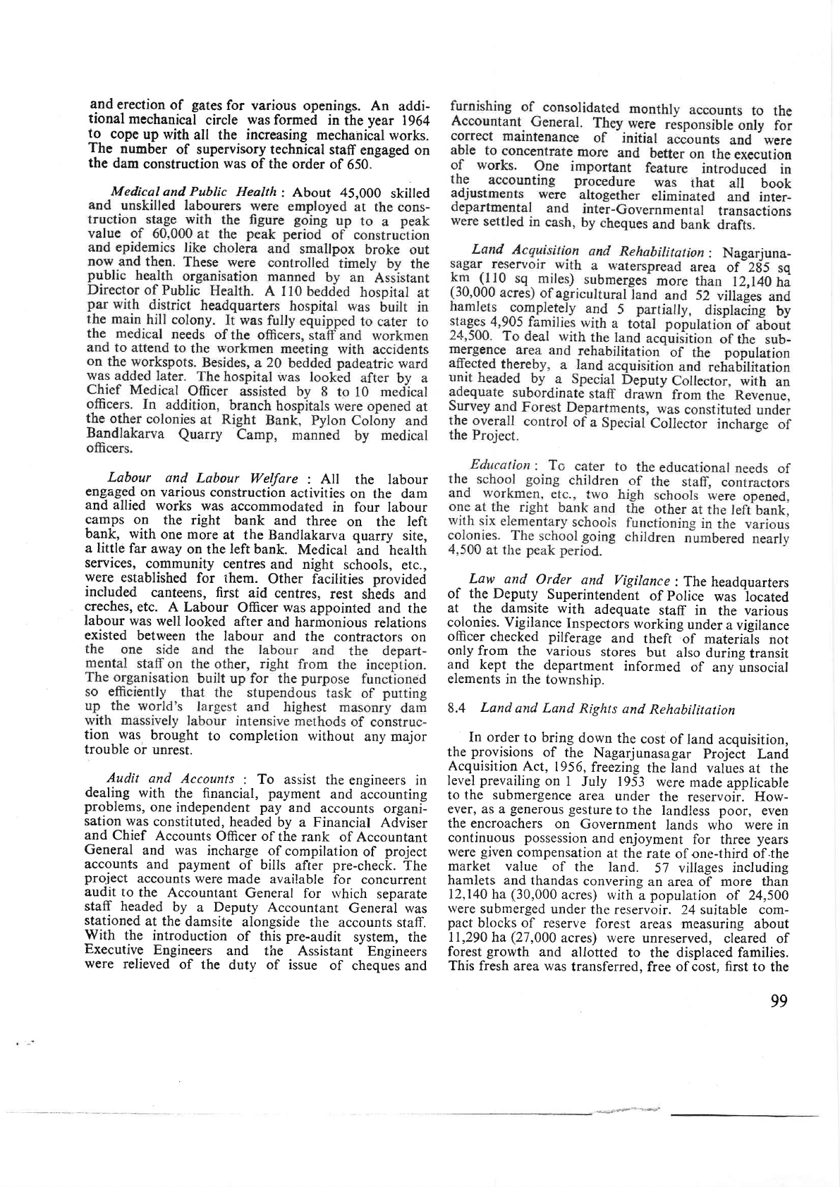
PHOTO
3: Blaw-Knox
batching
plant.
the
tunnel.
Blasted
muck was loaded
by
a
1
cu m
(1;5
cu
yd)
loader
into
5 cu m
(7.5
cu
yd)
dumpers
and
brought
outside.
The
progress
made in tunnelling
was
about
2.5
m
(5.2
f0 in 16 hours. The
entire
tunnel
for
a length
of
786
m
(2,580
ft)
was
completed
in
about
9
months.
The
total
quantity
of rock
excavated
was
62,300
cu m
(22
lakh cu
fr). The
entire El.
+91.44
m
(300
ft) tunnel
rvas
bored through
good
granite
rock.
The
goose
neck tunnel
at
El. 121.92 m
(400
ft)
was
excavated through shales
in
the first 25 m
(82
f0
length.
In
this case, a
small
pilot
tunnei of
size
7.2
m
x
2.1
m
(4ft
x
7ft)wasexcavated first,
top
half
of the
tunnel
next in
short
lengths
and the
rock
in
the
roof supported with
heavy
steel sections
and
wedges.
Later otr,
the bottom
half
was
excavated.
A
number
of
perfo
bolts were dri.ren even in
the
El.
+
91.44
m
(300
ft) tunnel at
places
where it was
excavated
through
weak
granite
rock.
Concrete Lining:
The tunnel
was
lined with
minimurir
0.3
m
(1
f0
thick concrete
lining
with
nominal
reinforcement.
Invert
of the
tunnel
was
lined
first
for
the
full
length.
Then
prefabricated
steel
shuttering
for sides
and
arch
in standard
lengths of
'I2.2
m
(40
ft) was
erected
and concrete
pumped
by
means
of a
pneumatic
placy
of 0.76
cu m
(1
cu
yd)
capacity.
Concrete was
manufactured
outside and
conveyed
inside
the
tunnel
by
Letournou dumpers and
104
fed
into
the hopper
of
placy.
The progress
achieved
on
lining
including
tying
grills
was
IZZ m
1+OO
ft)
per
month. The
total
quantity
of concreting
involved
was
12,744
cu
m
(4.5
lakh
cu ft).
Plugging
of El. 91.44
m
(300
ft)
Tunnel
:
The iriga-
tion needs
of Krishna
delta
were
kept in
view
in
programming
the
plugging
operations.
Water
was
not
required in
the month of
May
but
it
should be
ensured
on lst
June
without
interruption.
On
29
April 1967,
when
the
reservoir
was
at
El. 100 rn
(330
ft),
gates
were
lowered,
work
on
plugging
taken
up
round
the clock
and
2,270
cu
m
(80,000
cu
ft)
of concrete laid
in the
zone
of
first
phase
of
plug
before 30 May
1967,leaving
a ventway
of
18.6
sq m
(200
sq
ft) belowthe
roof.
On
7
June
7967, the
gates
were
operated
to release
waters
to
Krishna
delta
through
the
vent
left
above the
partial
plug.
This was
continued
till
the reservoir was
built
up to El. 119
m
(390
ft), when the
gates
were
again
lowered
on
28
July
1967,
and
laying
of
concrete
in the
second
phase
of
plug
taken up
and
completed in less
than
7
days. By
this
time'
the reservoir rose
to El.
125
m
(410
f0 and
the
gates
of El.
122
m
(400
ft)
tunnel
were
operated to
release water
to
Krishna delta
on
4
August
1967.
This
was
continued
till
the waters
overflowed
the spillway
at
El.
160
m
(52-<
ft).
Later
on
the
gates
of
El. 122 m
(400
ft)
tunnel
were
lowered and
the
third and
last
phase
of
plug
was
completed
with
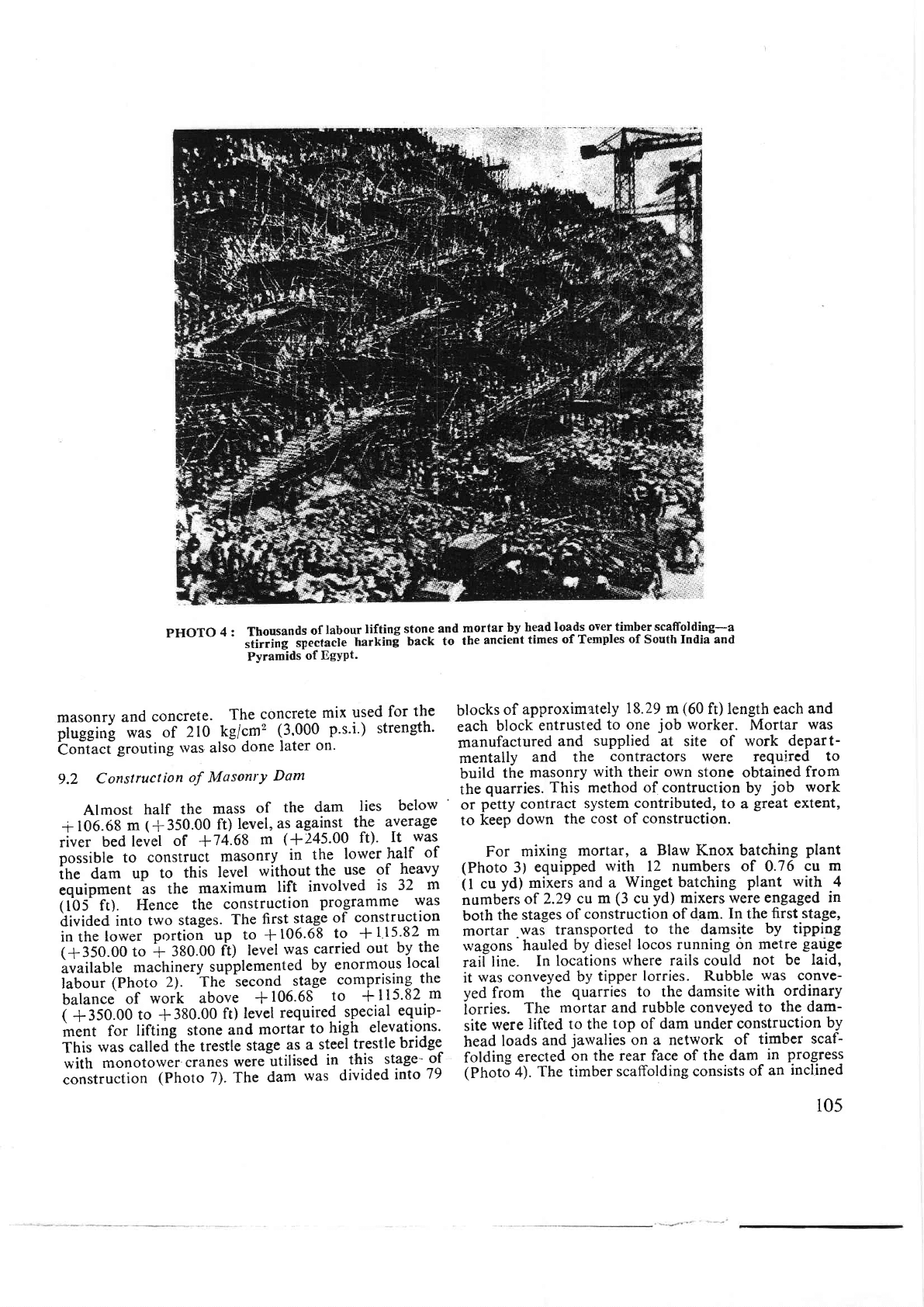
pHOTO
4 :
Thousands
of
labour
lifting
s_ton_e
and
mortar-by
head
loads over timbet
scaffoliling-a
stirrin!--sp"ttact"
harkinf
back
to
theancienttimesofTemplesof
Southlndiaand
PYramids
of EgYPt'
masonry
and
concrete.
The
concrete
mix
used
for
the
pfuggin!
was
of
210
Ag/cm2
(3.000
p's'i') strength'
bontacigrouting
was
also
done
later
on'
9.2
Construction
of
MasonrY
Dam
Almost
half the
mass
of
the
dam
lies
below
-r
106.68
m
(+350.00 ft)
level,
as
agains-t
t!9
average
tiu.t
bed
level
of
+74.68
m
(+245'00
ft)'
It
was
pottiUt. to construct
masonry
in
the
lower
half
of
itt"
du*
up
to
this
level
without
the
use of
heavy
equipment
bs
the
maximum
lift
involved
is
32
m
(tb5-
ft).
Hence
the
construction
programme
was
divided
into
two
stages.
The
first
stage
of
con_struction
in
the
lower
portioi up
to
*
106.68
to
*
115'82
m
(+350.00 to
*
380.00
ft)
level
was
carried
out
by
the
ivaitable
machinery
supplemented
by
enormous
local
f"U""i
(photo
2).
h6e^
iecond
stage
cornprising_the
balance
of
work
above
+106.6E
to
*115'82
m
i
ilso.o0
to
*380.00
ft)
levcl
required.special
equip-
*."t
for
lifting
stone
and
mortar
to
high
elevations.
This
rvas
calted-the
trestle
stage
as a
steel
trestle
bridge
with
monotorver
cranes
were
utilised
in
this
stage-
-o^f
conitruction
(Photo
7).
The
dam
was divided
into
79
blocks
of
approximately
18.29
m
(60
ft) length
each
and
each
block
entrusted
to
one
job
worker.
Mortar
was
manufactured
and
supplied
at site of work
depart-
mentally
and the
contractors were
required
to
build
the
masonry
with
their
own
stone
obtained
from
the
quarries.
This method of contruction
by
job
work
or
petty
contract
system
contributed,
to
a
great
extent,
to
keep
down
the
cost of construction.
For
mixing
mortar,
a
Blaw
Knox
batching
plant
(Photo
3)
equipped
with
12
numbers
of 0.76
cu
m
(
I
cu
yd)
mixers
and a
Winget batching
plant
with 4
numblrs
of
2.29
cu
m
(3
cu
yd)
mixers
were engaged
in
both
the
stages
of
construction of
dam. In
the
first stage,
mortar
was transported
to
the
damsite
by tipping
wagons'hauled
by diesel
locos
running 6n
metre
gld€-c
raif
line.
In
locations
where
rails could
not be
laid,
it
was
conveyed
by
tipper
lorries. Rubble
was
conve-
yed from
the
quarries
to the
damsite
with
ordi-nary
iorries.
The
mortar
and
rubble conveyed
to
the
dam-
site
were
lifted to
the
top of
dam
under construction
by
head
loads
and
jawalies
on a network
of
timber
scaf-
folding
erected
on the
rear face of the
dam
in
progress
(Photo
4).
The timber
scaffolding consists
of
an
inclined
105