Indian National Committee on Large Dams. Design and Construction Features of Selected Dams in India
Подождите немного. Документ загружается.

4.2
Structural
Design
of
Dams
(I)
MesoNRy
Dau
.
Stability
Analysrs:
Th
IilJJ'
#:'!ffi.:i.#
l;';f;
zero
at
the
downsrream
,il
jf?n33'lr?5:
?:t',ro
#1
the
full
base
area
was
considered.
No
seismi"
Tor..t
were
considered
as
the area
was
not
covered
by
the
seismic
belt.
As
the
reservoir
has
got
u
turg"
-
dead
storage,
of
about-82.30
m
(270
ft)
height,
silt
pressure
up
to
the
sill
of
the
riveroutlets,
ile.,-up
to
about
56-39
m
(185
ft)
above
the
river
bed
levil
ivas
conside-
red
in
the
design.
No
tension was
aflowed
in
the
section
under
uotrr
full
reservoir
and
reservoir
empty
conditions.
However,
under
the
maximum
water-
Ievel
conditions,
a tension
up
to 0.35
fcg/
sq
cm
(S p.i.i.)
was
allowed.
stability
analysis
revealeZ
thut
th.
-criti-
cal
section
would
be-at
the
floor
level
of the
drainage
g?-llely a-nd
hence.
the
starting
elevation
of
the oprtr.u"rr
tillet
had
a
certain
relationihip
with
..rp..t'
to the
location
of
the
gallery,
especii.lly
under
ih-.-.a*itrum
water-level
conditions.
A-maximum
value
of
0.7
for
the
coefficient
of
friction
and
a
minimum
value
of
5
for
the
shear
friction
factors
were
considered
in
the
design
with
a shear
resistance
of 28.12
kg/sq
iro
(400
p.s-i.)
for
masonry.
-
Assumptions
made
in
the
Analysis
: The various
lorces
considered
in
the
stability
analysis
are
(t)
self-weight
of dam
excluding
the
weight
of
equipment
and
other
fixtures
as
well
is
live
load
on
the
roadway
on top of
dam,
(ii)
vertical
weight
of water
on
the inclined
portion
of
the upstream
face
of dam,
(iii)
horizontal
water
pressure
on
the
upstream
face
of
dam,
(iv)
silt. pressure
on
the upstream
face up
to the
sluice
level
of
*
l34.ll
m
(+440
ft),
and
(v)
uplift
pressure
rvith
full
head
at
the
upsrream
heel
reducing
to 50
percent
at
the
drainage
hole
and
reducing
to zero
at
the
downstream
toe
of tbe
dam
section.
Tail
water
effect
was
not
considered
as
it
rvould give
sater
results
and
seismic
forces
also
were
not conslde-
red
as
the
dam
was
not
located
in
the seismic
belt.
The
rveights
of
nraterials
considered
are
:
(f)
random
rubble
masonrv
24OO
ks/*'
(150
lb/cu
ft),
86
(ii)
cernent
concrete
(fii)
rvater
(iu)
submerged
silt
The
safe
values
and
analysis
are
:
at
toe
:240A
kg/mt (150
lb/cu
fr).
:100-0
kg/mt (62.5lb/cu
ft),
and
:900
kg/m'
(56
lb/cu
fr).
coefficients
considered
in
the
(t)
allowable
compression
in
masonry:32.g1
kg/
cmz
(30
tons/sq
ft),
(ii)
allowable
compression
in concrete:43.75
kgl
cms (40
tons/sq
ft),
(iif)
allowable
tension
in
masonry
and
concrete:
zero,
(l'u)
shearing.
strength
of
rl?sonr!:2g.12
kg/cm2
(400
p.s.i.),
(v)
coefficient
of
static
friction
of masonry:0.7,
(vi)
angle
of
repose
of
submer_eed
silt:30o,
(uii)
maximum
allowable
sliding
factor:0.75
to
0.g,
and
(viii)
Minimum
value
of
shear
friction
factor:4.5
to
5.0.
Procedure
Followed
srep
I : The
horizontal,
vertical
and
shear
stresses
at
.any^
point
along
any
horizontal
plane
section
in the
body
of
the dam
were
calculated
utiiising
the
following
equations.
(i)
Vertical
stress,
i.e.,
normal
stress
on
horizontal
plane,
or--alby,
(if)
shear
stress,
rza:ar{bry}-cry2,
and
(iii)
horizontal
stress,
i.e.,
normal
stress
on vertical
plane-
,
6,,:oz*bzy
*tczy,
+*dryt,
rvlrere,
y
is
the horizontal
distance
up
to
the
point
under
consideration
from
the
downstream
ena
of
the
plane
section.
The
dam
profile
rvas
divided
into
a n*tru.t
of
horizontal planes
according
to convenience
and the
equations
for
62,6!t
and
azs
are
obtained
for
each
plane.
Srep 2 : The
constants
were
evaluated
from
the
following
equations
:
where,
6zD
analysis.
and 6zu
were obtained
from stability
fve
sign was
taken,
otherwise
-ve
sign.
Alternative
sign would give
the
value
of
crr, which
is
perpendicular
to
oor.
l_
,or:itan-r
f, =.
=""
I
t
l(
""
="" \l
(\
2
))
In
effect,
the
vertical
stress
on
a
horizontal plane
P7,
wofks
out
to
b:base
rvidth
of
dam
section,
and
e:eccentricity
of
the
resultant
force, and
the
principal
stress,
p,
at
the end
will
be
P:pv
sec2
{
where,
S:angle
of
inclination
of
the
face
of dam
to
the
vertical.
And
sliding
factor
:-W+
,
and
shear
friction
factor:
(w-
U)
tan
6+,qc
H
where,
l:base
area of
the
dam
section.
C:Cohesion,
and
H:horizontal
thrust.
dr:a
zltD,
,
ll->,v
Dt:
--Fl
o
z,
r\L
^
| (. Ev
-^- r
c1:@
(
o
=-f
Jazyu
t
a2uD:6zD
tan
$o,
and
ruzr:-(a"u-p)
tan
$"
*2t
"r"
*
Or
rrr),
3r,oo
).
whEre
Qe:6'aD
In
evaluating
the other
constants,
i.e., br,
cr,
and
dr,
the
following
assumptions were
made.
'c
zlr
Pv:!;L(-,+e)
where,
W:vertical
weight
of
dam,
U:uplift
head,
rvhich
at
the
ends-
+('*)xtan
S
Differentiating
the equation,
o
r:
ct
2*
b
zl
*
*
c
z!2
*
idu!"
dt
\
f
l
61t
):b'+"!*dil2
Equating (l)
and
(2)
d(
\
,tr
(
'",
)tan
$:6'*czY]-dr!2
. ..
(1)
...(2)
...(3)
...(4)
Putting
./:0
in
the
Equation
(4)
for
downstream
end and
differentiating
the
actual
equation of
r,o
already
obtained.
bz
was
evaluated.
The
other
two
constants,
cr.and
dr, were
obtained
by
solving Equa-
tions
(1)
and
(4)
simultaneously
rvith
the upstreim
end
value
of horizontal
stress,
i.e.,
oo,,
6!p:r.gD
tan
$o*p"
6.tu:Pn-Truu
tan
$u
vertical
planes
were
calculated
by
putting
the
values of
!', !2,
yrin
the respective
equations.
Srep
4
: The
principal
stress
and
their inclinations
were
then
obtained
for
each intersection point
with
the
following
assumptions.
orl:@--f...'.=l.'
2
f\i\
z
/*\'",/
In this
equation,
if
c"-or)0,
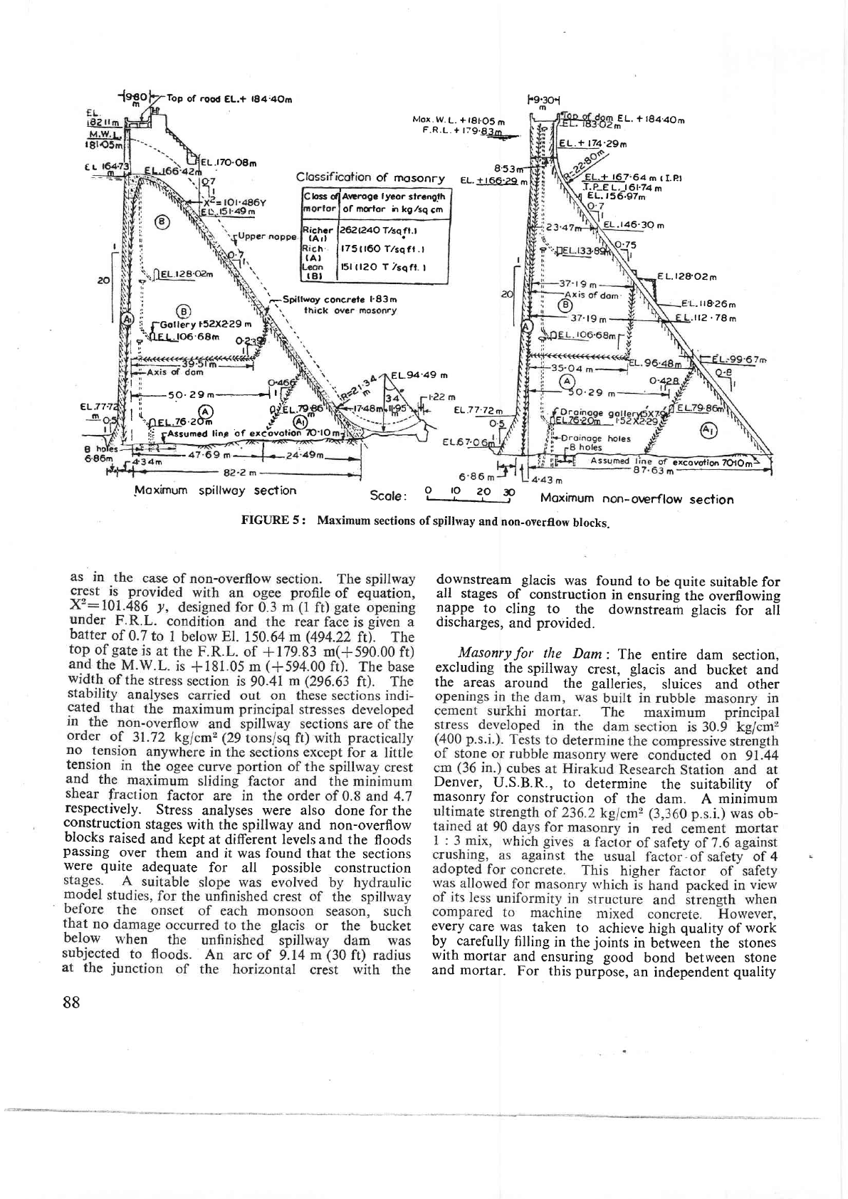
level.
The
front
batter
is I
in
20
berween
EI. i7.72
and,
166.29
m
(255.00
and
545.57
fi).
The
fronr
face is
vertical
above
El.
166.29
m
$45.57
ft)
and the
toe
below
El.
77.72
m (255.00
ft)
is
given
a batter
of.
I in
2. The
base
rvidth
of
the
section at
El.
64.00 m
(210.00
ft)
works
out
to
98.92
m
(324.53
ft). Similarlr..
the
maximum
spilhvay
section
analysed
'is
96.32
i
(316
ft)
high
between
the
lorvest
general
foundation
level
of
+70.10
m
(+230.00
ft)
and the crest
level
of
+.166.42
m
(+546.00
ft).
It
is
given
a
fronr
batter of
I in
20
above
El.
77.72
m
(255.0b
ftl. The
face
barter
of
the front
toe
below
E\.77.72
m
(255.00
ft)
is t
jn2
-'1rt-F
'ul
87
-{nHo
Top
of
rood
EL.+
t84:4om
L.l70-08m
Mox.W-L.
+l8t.O5m
F.R.L.
+
r;9€J4_.
8'53nr-
of mosonry
EL.+r66.2q
m
Fe.3ol
m
I
EL
EL.+ 174.29m
EL.
+
rSq.aom
m
.ta6.30
m
EL.+
t67,64
rn
{ I.pl
-T.P_E
L,
t61.74
m
EL.
r56.97m
8L.94'49
m
L.128'02m
-
tr8.26m
l12
.78
m
excovotion
TO|Om
eLi77
m
respectively.
Stress
analyses were
also
done
for the
construction
stages
with the
spillway and
non-overflow
blocks
raised
anA
kept at
different
llvels
and the
floods
passing
over
them
and
it
was found
that the
sections
were quite
adequate
for
all
possible
construction
88
EL.77.72m
lvloximum
spillwoy section
Scole'
?
'9
qo
-?
Moximum
non-orv€rflow
section
FIGURE 5:
Maximum
sections
of spitlway
and non-oyerflow
brocks.
d-ownstream
glacis
was
found
to
be
quite
suitable
for
all stages
of
construction
in
ensuring
the
overflowing
lSppe
to
cling
to the
downstream glacis
for a[
discharges,
and
provided.
Masonryfor
the
Dam:
The
entire dam
section,
excluding
the
spillway
crest,
glacis
and
bucket and
the areas
around
the
galleries,
sluices
and
other
Denver,
U.S.B.R.,
to determine
the
suitability
of
masonry
for
construcrion
of the
dam. A
minimum
every
care
was
taken
to
achieve
high
quality
of
work
by
-
carefully
filling
in
the
joints
in
between the stones
with
mortar
and
ensuring- good
bond
between
stone
and mortar.
For
this
purpbse,
an
independent
quality
bss
dlAeroge
lyeor
slrcnglh
of
mclor
h kglsq
cm
i*i.
f*o"orlsqfr.l
h.
If75r160T/sqft.l
tAl
l5l
t
l2O
T 7sqft.
I
t8l
75
ig
{-Gollery
r52X229
m
.::t---Ie
l. toa.sam
OZ:
F.-(/
H-5.O.29
m----+i
I
|
(..'.-.ru.P
gt?#
I
n.g-Eulo.zb#
.{
(AD"'
I
lf
rAsrrmed
tin€
"f
.r.""".fi"Yrcj
t-Srilt*ov
concrele
l'83
m
,\
-
1
admixture
of
surlfr.i,
the
mortar was
called
red
cement
mortar.
Air-entraining
agent
also
was
used
in
all
cement
mortar
and
cement
concrete mixes
to improve
section, as
indicated
below,
depending
on the
magni-
tude
of the
stresses
developed
in those
regions.
(i)
A,
type,
richer
mix of
I
: 3 by
weight,
in the
highly
stressed
regions in the downstream
toe
portion
where
the
stresses developed
are
more
lhan
21.87 kg/cm2
(20
tons/sq
ft)
as
well
as
in
the
front
2.7 m
(9
ft) thick
layer
for
imperviousness,
(tt) A tJpe,
rich
mix of I : 3.91-
by-weiglt,
in
the
regions
where
the stresses
developed
are
morc
than
16.40
kg/cm2
(15
tons/sq
ft)
and
less
than
21.87
kg/cmz
(20
tons
sq ft), and
(ttt) B type,
lean
mix of 1
:
4-71by
weiglt,
in
the
regions
where
the
stresses -developed
are
less
thin
16.40
kg/cm2
(15
tons/sq ft).
masonry.
-.-et/+d
*
89
Axis
of Oom--
-
- ln.'r^
Y1r-
EL.t82'9m
(EL.
+ 6oooori
EL.t8l
m'
r
EL
+
594'OOl
M.W.L.
l'22
m lhigk rip-rop
U/S
Rock-fitl
Conol
excovoted
moleriol
Grouf
hotes 9'lm
deep
ot
6'lm
C/C
5
O 5
l5m
|'-J--J-J
E
L.18l
rnox.
W.
(L
trpe."ious
R
ight eo
rth
dom
eu.oOo'o1
|
U/S
Fock
ftlt
ercovoled moleriol ?o'7m
3
m( ldt
fltler
-Turfino
EL.t75'26
m
t-
3m
*
3
EL.I
l'2m
dumpad
rip-roPover
-
O.76m
f
ilter
3m
EL.16ZOm
r
I
2
ffl*f-
r'2m+
ho|es
94m
deGP
6'l
m
C,/C
Left eorth
dom
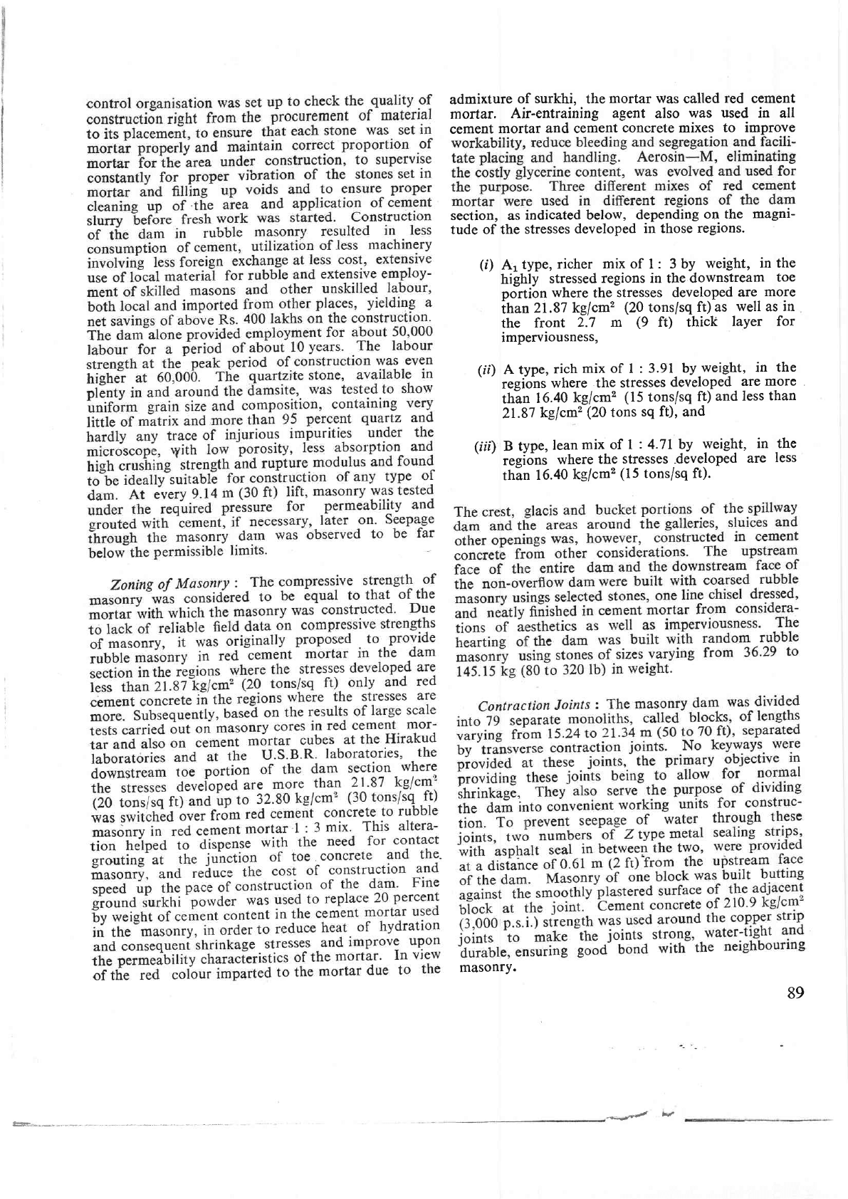
FIGURE
6 : Maximum
sections
of
earth
dam.
3.,
gp
:i'--Grour
ol
masonry
from
the
front
face
of
dam
and
collect
in
the dra-ins
provided
in
the
three
drainage galleries.
In
addition,
the
foundation gallery
served
io carry
ou.t..high_pressure
curtain
grouting
and subsequent
drilling
of drainage
holes.
This
gallery
also
serves
to
measure
uplift
-pressures
and
read
the
other
measuring
instruments
embedded
in
the
dam.
The
toe gallery
was
originally,
intended
to
carry
out contact
{routing
at
the
junction
of concrete
toe
originally
provided
ind
the masogy.
-
By
switching
over
to
-masonry
in
this
toe
portion
also, this
toe
gallery
now
serves
for
the
location
of
the
terminal
boxes
of
the
instruments
embedded
in
this
porrion
of
the
dam.
All
these
galleries
serve
for
inspection
purposes
as
well and
they
are interconnected
by
means
of
shafts
and
suitable
adits.
In
addition,
two
elevator
towers
are
provided
at
either end
of
the spillway
dam,
connectin!
ali these
galleries
to
the
top
of
dam, with
electric-al
lifts
and
winding
staircases=
inside.
Enfiedded
Instruments
:
Resistance
thermometers
to
measure
the temperature
rise
in
masonry,
stress
and
strain metres to
record
the
stresses
in
ihe
dam
and
joint
metres.to
measure
the
extent
of
openings
at the
contraction
joints_and
other
places
and-
pore
pressure
cells
were
embedded
in
the
body
of
ihe dim with
E
L.
t58'5m
Rock-fill
--Axis
of
dom
r
19'l2nt
try
their
terminals
led
into
terminal
boxes located
in
the
galleries.
Plumb
bob
wells
were
provided
in
two
blocks
of
the
dam,
one on each
flank,
to
measure
the
deflection
or
tilt of the
dam.
Uplift
pressure
pipes
were
installed
in
the
foundation
gallery
to measure
the
uplift
forces
on the dam.
Piezometers
were also
embedded
to
measure
the
pressures
on
the
spillway
glacis
and
sides of river
training
walls.
All told, 129
numbers
of instruments were
embedded in
the
masonrv
dam-14 stress
meters,
28
strain
meters,
14
joini
meters,
63 thermometers
and
10
pore pressure
cells.
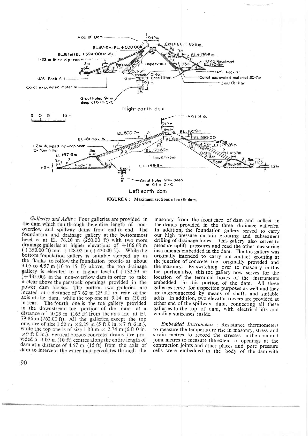
(2)
En
nu{Deus
(Frcunn
6)
Left
Earth
Dam: The left
earth dam
is a zoned
embankment
with central
impervious
core covered
with
semi-pervious
earthfill
on
either
side.
There
are
three
hills,
with
two saddles
between,
on the
left
flank
of
thc
dam.
Earth
dam
was
constructed in
these two
saddles
and in continuation of
the
masonrv dam
towards
the
flanking
hill. The lowest
foundation
level
of
this
eafth dam
is
at EI.
158.50 m
(520
ft)
and
the
top of
dam is
kept at
El. 186.00
m
(610.00
ft),
1.52 m
(5
ft)
higher
than the top
of
masonry
dam. The
maximum
height of this
earth dam is
27.4 m
(90
ft).
The
top width of
dam
is
kept at 9.30
m
(30
ft
6
in.).
The
front slope is
kept at
3
:
I and rear slope
at
2
:
1.
Trvo
berms
of 5.49
m
(15
ft)
width
each are
provided
on the
rear slope, one at
El.
175.30 m
(575.00
ft)
and
the
otherat
El. 166.10
m
,(545.00
ft).
Rock
toes
are
provided
both
for upstream
and downstream
slopes.
The
upstream slope
is
protected
with
1.22
m
(4
f0
thick
dumped riprap
provided
over
0.76
m
(2
ft
6 in.)
thick
f.lter,
while
turfing
is
provided
on
the
down-
stream
slope above
rock toes. Longitudinal drains
at
9.14
m
(30
fD intervals
and transverse sloping
drains
at
30.48
m
(100
ft) intervals
are
provided
on the down-
stream
of the dam
section
to drain the
rain
water.
The
impervious soil
and
gravel
required to form this
earth
dam
were
brought
from the
water
spread
area
above
the dam with
a
lead of
about
6.4
to 8.0 km
(4
to
5 miles).
The
soils
were
tested for suitability
and
the following
are
their
properties.
Gravel content
Sand
content
Silt
content
CIay
content'
Impervious Semi-pervious
soil
soil
15
percent
36
percent
52
percent
42
percent
11
percent
14
percent
22
perceht
8
percent
Total
fines
content
33
percent
22
percent
Angle
of
internal
friction,
t'
200
250
Cohesion
in
kg/cm,
(lb/sq
ft)
0.245
(500)
0.196
(400)
Percentage
moisture
at o.M.c.
Coefficient
of
permeability
I
in cm/sec
1ft/year) |
J
11to14
9to11
percent
percent
4.8
x l0-G 67
x
10-6
to
to
9.6
x 10-6
135
x
10-6
(5
to l0)
(70to
1a0)
t
181.05
m
(
+
594
ft),
the
factor
of
safety for
the
downstream
slope
was
worked
out
to 1.28.
Right
Earth
Dam:
The
right
earth dam
is
also
a
zoned
embankment
with
central
impervious
core.
But,
as suitable
semi-pervious
soils wert
not
available
within
reasonable
leads,
the
impervious
core was
covered
on
either
side
for
this
earth dam with
the
canal
and tunnel
excavated
rock
muck available within
short leads,
unlike in
the case
of
the
left
earth
dam,
which
resulted
in
considerable
economy in the
cost of
construction.
The
top
width
of thii dam
is
kept at
9.14 m
(30
ft). The
upstream
slope varies
from 2: I
above
El. 181
m
(594
ft) to
3 : 1
below.
The
down-
stream
slope is kept
at2:.
l. Suitable
filters
of
1.52
m
(5
ft) thickness
are
provided
on
either
face of
the
impervious
core. Suitable
rock
toes
also are
provided
for both the slopes.
The upstream
slope
is
protected
with 1.22 m
(4
ft)
thick
riprap
and the downstream
slope
with
0.46 m
(1
ft 6 in.)
thick
revetment. One
berm
of
3.05 m
(10
f0
width
is
provided
on
the
downstream
slope at
El.
176.8
m
(5S0
fr).
This
earrh
dam
section
also
rvas
desi_ened
b.v
Swedish slip circle
method.
Impervious
Semi-pervious
soii
soil
Liquid
limit
Plastic
limit
Saturated
weight
in
ks/*'(lb/cu
ft) 2150
(134)
30
percent
38
percent
16
percent
20
percent
Gravel
content
Sand
conteni
Silt
content
Clay
content
Total
fines
content
Liquid
limit
Plastic
limit
Saturated
weight in
kg/m'
(lb/cu
ft)
0
percent
52
percent
l4
percent
-14
percent
48
percent
36
percent
17
percent
2150
(
r34)
40
percent
44
percent
4
percent
12
percent
l6
percent
-19
percent
20
percent
2res
(r37)
9l
2r9s
(r37)
Angle
of
internal
friction,
t'
Cohesion
in
kg/cm2
(lb/sq
ft)
Percentage
moisture
at
o.M.c.
Coefficient
of
permeabitity
in
cm/sec
(ft/year)
Impervious
Semi-imper-
soil vious
soil
10"
300
0.342
(700)
0.195
(400)
16
percent
ll
percent
13.5
x
l0-o
(14)
Embedded
Instruments
:
Cross-arms
and
piezo-
meters
were
installed
in
the
right
earth
dam
at
km 4.084
(ch.
134.00).
l0
piezometers
were
installed
here,
3
of foundation
type
in
the foundations
and
l0
of
embankment
type, I in
the semi-.pervious zone,
5
in
the
impervious
zone
and I in the excavated
rock
muck
zone. No
instruments
were
embedded
in
the left
earth dam.
5. Design
of Spillway
5.1
Design
Flood
Estimation
of spillway
design
flood
of Nagarjuna-
sagar Dam
became
a
problem
due to the
absence
of
any observed
data of
the
damsite. The
daily discharge
available
at
Vijayawada
anicut
which
is
situated about
176 km
(ll0
miles)
downstream ofthe
damsitewas
utilised in
arriving
at the
design flood.
Such
daily
discharge data was
available
for
a
period
of
60
years
from
the
years
1894
to 1954. Based
on
this
available
data,
frequency
studies
were
made
and
the 1000-year
design
flood was
computed
based
on
Gumbell's
method
taking
into
consideration
the
upper
confidence
limit
of
Ven-te-Chow
method.
The maximum
observed
flood
at
Vijayawada
anicut was
30,050 cumecs
(10.61
lakh
cusecs) in
the
year
l90l
and
the
corresponding
mode-
rated
flood rvas
conside
red
as 29.085 cumecs
(
10.27
lakh
cusecs). The
1000-year
flood
considered
in
the
original
desi-etr
of
spillway
was 39,220 cumecs
(13.85
lakh
cusecs) and
26
spans of
15.24
m
x
I 2.19 m
150
ft x
40 ft)
size,
rvith
3.05
m
(10
ft) thick
piers
in
berween,
were provided
with
crest at
*167.64
m
(+550.00
ft)
to surplus
an
unrouted
flood of the same
rnagnitude
at
F.R.L
+179.83
m
(+-590.00
ft). Subsequently
it
rvas
considered
reasonable
to
account
for
the valley
storage
obtaining
in
between the
damsite
and
Vijayawada
anicut
and
provide
for
a higher
flood
of
grearer
magnitude
at
the
damsite.
Accordingly, the design
flood
for Nagarjunasagar
spillway
was refixed
at
43,360
cumecs
(15.31
lakh
cusecs)
and the spilhvay
increased
to
26 spans
of 15.24
m x
13.41
m
(50
ft
x
44
ft)
uith-
the
same
3.05
m
(10
ft)
thick
piers
in betrveen,
but
$'ith
the
crest
lowered to
*,1
66.42
m
(+546.00
ft).
But,
later
during
construction,
stress
analysis
made
in
the region
around
the
reinforced concrete
pier
in
the
masonry
spillway
based on
photoelastic
studies
revealed
thar
a
4.57 m
(15
fr)
thick
pier
was required
and
provided.
With
this
increase in
the thickness of
pier
from
3.05
to
4.57 m(10 to 15 ft),
the span length
was reduced
from
15.24 to 13.72
m
(50
to 45
fr),
92
tion
effects
of
both
the
reservoirs
for integrated
operation
and
it
is
found
that
the
maximum
oltfloru
Nagarjun.asagar
Dams
of
the
order
of
about
g,500
cumecs
(3.00
lakh
cusecs).
The
maximum
outflow
5.2
Spillway
Profile
-
The
spillway
profile
consists
of
a compound
circular
curve of radii
equal
to
2.69
m
(g.g
ft) and
6.71 m
{22
ft) on
the upsrream
side
of
the crest
at Et. 166.42
m
(546
f0, connected
to
the
downstream glacis
of 0.7
to
! -with
an o_gee
_curve
of
parabolic
shape
of equation
X2:101.436
f.
Hydraulic-model
studiei were
carried
cut
-on
this
profile
to study
the
stability
of the
crest
profile, pressures
on
the
crest
as
well
as on
the down-
stream
glacis
and
discharges
for variorrs
depths
of flow
and
various
gate
openings.
These
studies
indicated
that
the
coefficient
or
discharge
for
this
profile
varies
from
2.7
to 3.95
depending
o;
the depth
of
florv
over
the
crest
and the maximum
value
of
3.95 is
attained
at
of 6.71 m
(22
f0 thickness
in
the
cresr
and
1.83
m
(6
fr)
thickness on
the
glacis
slope,
in
view
of the
very
high
velocities
of florv
of not
less
than 8.23
misec
(27
ftlsec)
obtainin_e in
M.W.L.
conditions.
5.3
Spillv'ay
Bucket
Energy
dissipating
arrangements
provided
below
the
spillway
section
were
evolved
with the aid of hydraulic
model
experiments.
Several
types
o[
energy
dissipating
devices
were
considered
and.
out
of
alt
of
them,
three
types
were selected
for the
initial trials,
viz.,
the
stilling
basin,
the
interacting
jet
dissipator and
the
flip
bucket.
Preliminary
studies
carried
out revealed that the
deflector
or trajectory
type
of
flip
bucket
would
be
the
best
suited of
all the
three, considering both
economy
in construction and
efficiency
in
perflormance.
The
guiding
factor
in
selecting
this type of
bucket
for
Nagarjunasagar
spillway
was
the
presence
of
sheet
rock
of
hard
granite
variety,
which
is
not
easily
erodable,
downstream
of the
spillway,
which
does
not
justify
the
much
higher cost involved
in either
of the
other
two
types.
Even
this
flip
bucket
was originally designed
with a
radius of 27.43
m
(90
ft), keeping the invert at
the
average
river
bed
level of
+73.15
m
(+240.00
f0
at
the
site
with
an angle
of
projection
of 30"
and
flip
elevation
at
+76.81
m
(+252.00
ft).
Again
hydraulic
model
studies
carried
out
on the
flip
bucket
with
different
radii,
different
flip
angles and
flip
elevations
and
different
invert levels,
indicated
that
a
bucket
rvith
a radius
of
2I-34
m
(70
ft) and angle
of
projection of
34"
with
the
same invert
and flip
elevations
is
as
efficient
as ihe 27.34
m
(90
ft) radius
bucket,
the
flow
features
observed
in both the setups, such as
the height
and
range
of
the
trajectory
of the
nappe,
the
pressures
obtaining
on
the
bucket and
the
erosion
characteristics
in
the
mobile bed
simulated below
in
the model,
being
almost
identical.
It
was
also
observed that the
pres-
sures
exerted
on
the
bucket
were
quite
within
the
practicable
limits and
that
the
sheet
of rvater
projecteQ
from
the
bucket
was
quite
stable up to a tail
water-level
of
+85.34
m
(+280.00
ft),
and
free
from
negative
pressures
even
at low head conditions and
that the
sheet
tended
to
become unstable resultin-e
in a submer-
ged
bucket
only
u'hen
the
tail
water-level
exceeded
+88.39
m
(*290.00
fil.
The
water
jet
was
thrown
off
to
a distance
of
about
12I.92 m
(400
ft).
away
from the
lip
of the
bucket
and impinged
on
the
water
cushion
built
up by
the tail
water.
The
adoption
of
21.34
m
(70
ft)
radius
flip
bucket
without
sacrificin-e,
in any'
way,
the
efficiency'
of
the energy
dissipation,
resulted
in a'savings
of
about
Rs.
12 lakhs. The
maximum
velocity of
rvater
in the
bucket
will
be
of the
order
of
46.O2
m/sec
(l5l
ft
sec)
and
high
pressures
of the
order
of
32,891
k,eim2
(6,740lb1sq ft)
will
be developed
on
the
bucket under the
maximum discharge
conditions.
The
bucket
was
built
in
reinforced
cement
concrete
with
a
minimum thickness
of
1.52 m
(5
ft) at the
invert
pornt.
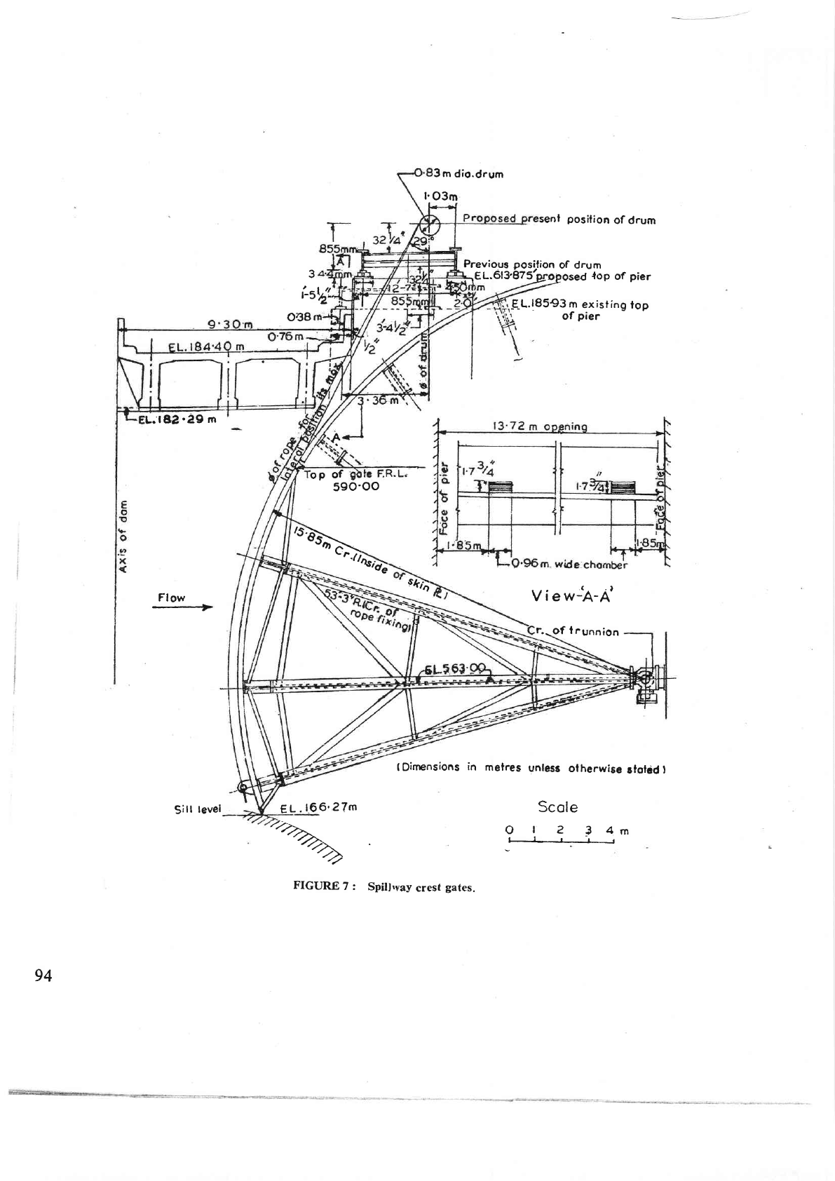
5.4
Crest
Gates
(Figure
7'1
The spillway
crest
at
El. 166.42
m
(546
ft)
was
fitted
with
radial
.eates
of size
13.72
m x 13.41
m
(45
ft
x
44
ft),
with top of
-sate
at
El.
179.83
m
(590ft)
and
with
rope
drum
hoist
and the
operation
hoist
platform
at El, 187.11
m
(613.875
ft).
No
separate
large
scale
outlet
arrangements
are
provided
fbr
the
reservoir
for
operation
at higher
reservoir
levels,
except
for
the
diversion-cum-irrigation
tunnel
and chute
sluices
at
lower levels.
These
crest
gates
are
intended
for
not
o-nly
surplussing
high
floods
over
the
spillway
but also for regulation
of the
outflows
from
the
reser-
voir
when
the reservoir is
at higher levels. The
effects
of
partial
gate
openings
and
unequal
gate
openings,
with
adjoining
vents
closed,
were
studied by hydraulic
model
experiments
and
it was
observed
that
there
would
be
no
adverse
effect
on
the
spillway
glacis,
bucket
and the
flip
due
to
unequal
gate
openings.
Fressure
studies
were
also
made
on
the
spillway
piers
for
the
conditions
with
one
venr fully open
and the
adjacent
vent
closed
and with
both the adjacent
vents
fully open
and
the
pier
was
found
to be stable and
safe
for such
unequal
pressures.
The
gate
structure
and
the
over
bridge
were
to
be safe
for
the
normal condi-
tion
with
the reservoir
at F.R.L.
of
+
179.83
m
(+
590
ft),
i.e., water
standing
up to top of
gate
and
the
overtopping
condition
with
the
reservoir
at M.W.L.
of
+
181.05 m
(+594
ft).
But,
inasmuch
as
the
permissible
stress
in
the
members
for the
overtopping
condition may be
increased
by
33+
percent
while the
loading
goes
up by about
l0
percent
only, the
gate was
designed
for
the normal
condition.
The
rvei_eht of
gate
is
86.5
tonnes
(85.14
tons) and
a
6
H.P. motor
at720
r.p.m. is
provided
for
each
_qate.
6.
Design
of
Outlet
Works
6.1
The various
outlets
provided
in the
Nagarjuna-
sagar
Dam, in
addition to the
spillway.
ate
chute
sluices
at either
end
of spillway,
right canal
head sluice
in
the
right
non-overflow dam, with
a separate diver-
sion-cum-irrigation
tunnel bored
through
the Ieft
flank
and left
canal
head
sluice located separately
in
the
foreshore
of
.the
reservoir, apart
from
the
penstocks
and
power
sluices
provided
for
purposes
of
porver
development.
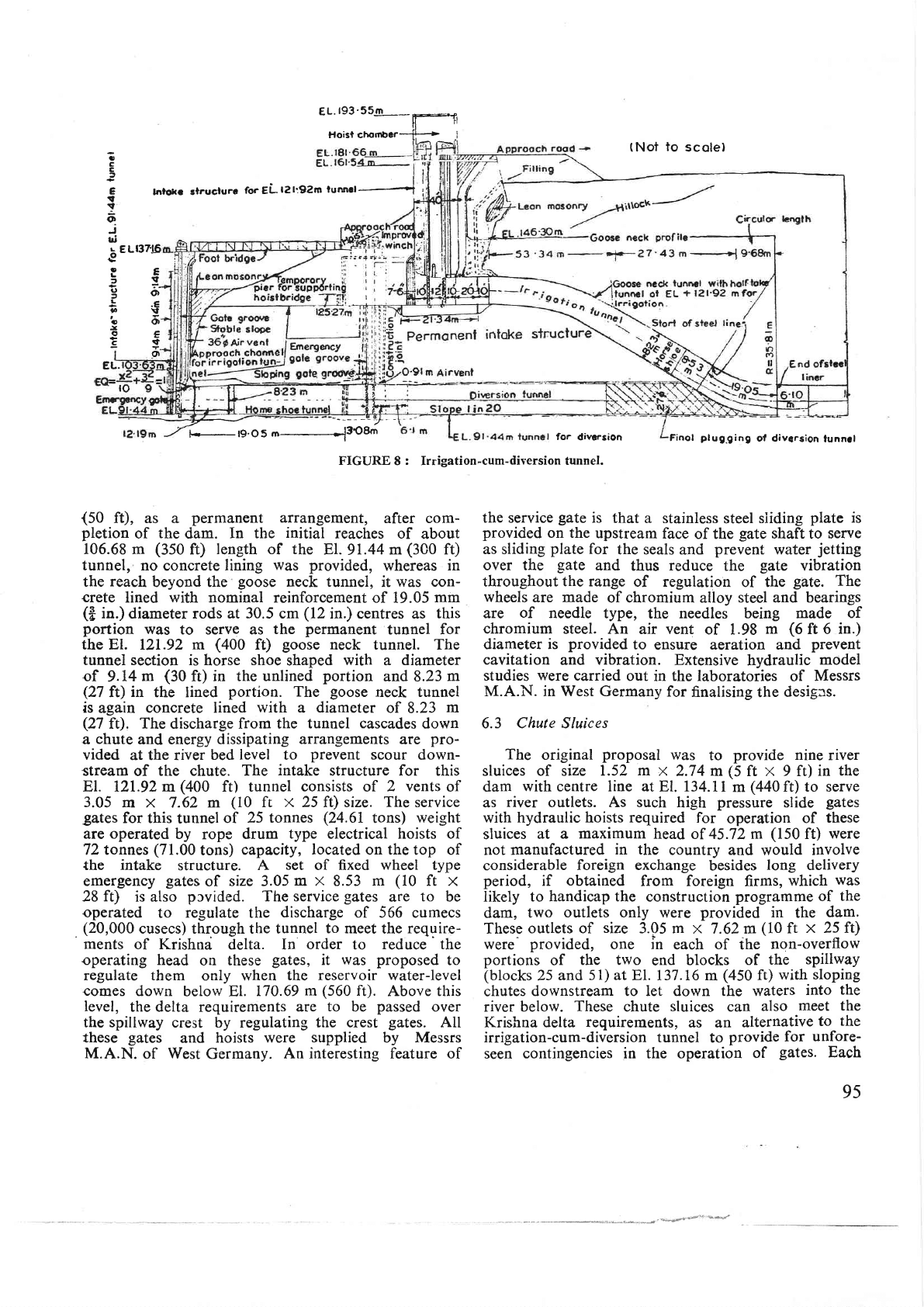
6.2
lrr\atiort-cum-Dit'ersion
Tunnel
(
Figure 8)
In
order to
facilitate
release of
irrigation
waters
for
the
Krishna
delta
both during the
period
of cons-
truction
of
the
dam
and after completion
of
the
dam,
it
rvas
earlier
proposed
to construct
18
river
sluices
at
E[.
129
54
m(a25 ft)
and 8
at
El.
l02.ll
m
(335
ft)
in
the
dam. But.
due
to
the
difficult
foreign
exchange
position
obtaining
at
the
time
of
the construction
of
the
dam
for
purchase
of the high
pressure
slide
gates
and
the
embedded
parts
required
for
these
sluices,
all
these
river
sluices
were
eliminated
and.
in
their
place, a diversion
tunnel
was
provided
on
the
left
flank
of
ttredam at
El.
91.44
m
(300
f0'
This
tunnel
was later
connected
with
a
goose neck
tunnel
at El.
121.92
m
(400
ft)
and
the
entrance
to
the
El.
91.44
m
(300
ft)
plugged
so
that
the
El.
121.92
m
(400
f0
tunnel can
p-ass
the
required
disclarg-e
of
i66..t*."s
(20.000
Cusecs)
undei
a
head
of
15.2 m
93
3
m
dio.drum
l.O3m
senl
position
of drum
W
3
t-5
O38
r
Previous
posi,tion
of drum
h8L.613875-gg.oposed
{op
of
pier
_E_L.185€3
m
existing
fop
;
of
pier
s,tD
V
ie wi-A'
r.-of
f runnion
(
Dirnensions
in
metres
unlese
olherwise
gtoldd
t
Scole
o
|
2
3
4m
l-,ll-
|
r
.
L.'t
82.29
m
Flow
+
Silt
tevel
.lA
op
of
s90'oo
"\
t.Au-
EL.l66'27m
FIGUR.E
7 :
Spilf
.vaV
crest
gates.
94
EL.193'55.3q-
tI
Hoi3t chornb"r-jf_,i
r37.!6
E
:.
Or
,E
v
o
E
rf
o
;
c
C
2
E
!
j
o
J
lri
rEL
{;
3
(,
L
I
,
3
:
o
I
lnloLe slruclurc
forELt2l:92m
funnrr--!
I
for
divcrsion
FIGURES :
Irrigation-cum-diversion
tunnel.
(Not
to
scole)
Finol
plug.ging
ol diversion
lunnll
EL.
to
{50
ft),
as a
permanent
arrangement,
after com-
pletion
of
the
dam.
In the
initial
reaches of
about
106.68 m
(350
ft)
length of rhe
El.
91.44
m
(3C0
f0
tunnel,
no
concrete
lining
was
provided,
whereas
in
the
reach
beyond the
goose
neck tunnel,
it
was con-
crete
lined
with
nominal reinforcement
of 19.05
mm
(B
in.)
diameter rods at
30.5
cm
(12
in.)
centres
as
this
portion
was
to serve as
the
permanent
tunnel for
the El.
12I.92
m
(400
f0
goose
neck tunnel. The
tunnel section is
horse
shoe
shaped
with
a
diameter
of
9.14
m
(30
ft) in the unlined
portion
and 8.23
m
(27
ft)
in
the lined
portion.
The
goose
neck tunnel
is
again
concrete lined
with
a
diameter
of
8.23
m
(27
ft),
The
discharge from
the tunnel
cascades
down
a
chute
and energy dissipating
arrangements
are
pro-
vided
at the river
bed
level
to
prevent
scour
down-
stream of the chute.
The
intake
structure for
this
El. 121.92 m
(400
ft) tunnel
consists
of
2
vents
of
3.05
m x
7.62
m
(10
ft
x
25 ft) size.
The
service
gates
for this
tunnel
of
25 tonnes
(24.6I
tons)
weight
are operated
by
rope
drum
type electrical hoists of
T2tonnes
(71.00
tons)
capacity,
located
on the top of
the
intake
structure.
A
set
of fixed
wheel type
emergency
gates
of
size 3.05
m x
8.53
m
(10
ft
x
28
ft)
is
also
prvided.
The service
gates
are
to
be
operated
to
regulate
the
discharge
of 566
cumecs
.
(20,000
cusecs) thr.ough the tunnel
to
meet the
require-
ments
of Krishna
delta. In
order
to
reduce the
operating head
on
these
gates,
it
was
proposed
to
regulate them
only when
the
reservoir
water-level
comes
down
below El.
170.69
m
(560
ft).
Above
this
level,
the delta requirements
are
to
be
passed
over
the spillway
crest by regulating
the crest
gates.
All
these
gates
and
hoists were
supplied
by Messrs
M.A.N.
of West
Germany.
An
interesting
feature of
the service
gate
is that
a stainle.ss
steel
siiding
plate
is
provided
on the
upstream
face
of
the
gate
shaft
to
serve
as sliding
plate
for
the seals
and
prevent
water
jetting
over the
gate
and
thus
reduce
the
gate
vibration
throughout
the range
of regulation
of the
gate. The
wheels
are
made
of chromium
alloy
steel and bearings
are
of
needle
type,
the
needles being made
of
chromium
steel. An
air vent
of 1.98
m
(6
ft 6
in.)
diameter
is
provided
to
ensure
aeration and
prevent
cavitation
and vibration. Extensive
hydraulic
model
studies
were
carried
out
in
the
laboratories of
Messrs
M.A.N. in West Germany
for
finalising
the
desiges.
6.3 Chute Sluices
The
original
proposal
was
to
provide nine
river
sluices of size
1.52 m
x
2.74
m
(5
ft x
9
ft)
in
the
dam
with
centre line at
El. 134.11
m
(440
ft) to serve
as
river outlets. As such
high
pressure
slide
gates
with hydraulic hoists
required
for
operation
of
these
sluices
at a maximum head
of 45.72 m
(l50ft)
were
not
manufactured
in the
country and
would
involve
considerable
foreign exchange
besides
long
delivery
period,
if
obtained
from foreign
firms,
which
was
likely to
handicap the
construction
programme of
the
dam,
two
outlets only
were
provided
in
the
dam.
These
outlets of
size
3.05 m
x 7.62 m
(10
ft
x 25 ft)
were
provided,
one in
each
of
the
non-overflow
portions
of
the two
end
blocks
of
the
spillway
(blocks
25
and
5l) at FI.
137.16
m
(450
ft)
with sloping
chutes
downstream to let down the waters
into
the
river
below.
These
chute
sluices
can
also
meet the
Krishna delta
requirements,
as an
alternative
to
the
irrigation-cum-diversion tunnel
to
provide for
unfore-
seen
contingencies in the operation
of
gates.
Each
aa*'
_-qPygvs#
95